display HONDA INTEGRA 1994 4.G Workshop Manual
[x] Cancel search | Manufacturer: HONDA, Model Year: 1994, Model line: INTEGRA, Model: HONDA INTEGRA 1994 4.GPages: 1413, PDF Size: 37.94 MB
Page 4 of 1413
,,
SUPPLEMENTAL RESTRAINT SYSTEM (SRS}
The Integra SRS includes a driver's airbag, located in the steering wheel hub. ln addition, all mod€ls excepi tna
Rs model for canada have a front passenger's airbsg located in the dashboard above the glove box, InformaUon
necessary to safely service the SRS is included in this servica Manual. ltems marked with an sstorisk (r) on thr
contents page include, or are located near, SRS components. Servicing. disassembling or roplacing thea6 ltems
will require special precautions and tools, and should thoreiore be done by an authorhed Acura dealer.
' To avoid rondering ths sRS inoporativo, which could lard to porronll Injury or darth In thc cvant ot. r.yr.
trontal collision, all sRs sorvico work must be pcrformcd by !n ruthorizcd Acu.! daerrr,
' lmpTopor 3orvica proceduroa, including inco.roct r.movd r d Installation of tha SRS, could Lld to pc[onc Inlu-
ry caussd by unintsntional activation ot tho airbags.
' All sRs oloctrical wiring harnoa$! aro coverod with yallow In3ulatlon, Rcbtcd componcnts arc bcrtad In tha
stoering Golumn, front console, dsrhboa.d, and darhboard lowor plnol, lnd in thc d$hbolrd abovc tha gaov!
bor. Do not uas oloctdcal te$ oquipmont on thaaa citcuhs.
NoTE: The original radio has a coded thett protection circuit. Be sure to get the customer's code numb6r b€lore* disconnecting the battery.
- removing the No. 32 (7.S A) fuse Jrom the undsr-hood fuse/relay box.
- removing the radio.
After service, reconnect power to the radio and turn it on. When the word ,,CODE,, is displayed, enter the cus_
tomer's 5-digit code to restore radio oDerauon.
Page 40 of 1413
Lubrication Points
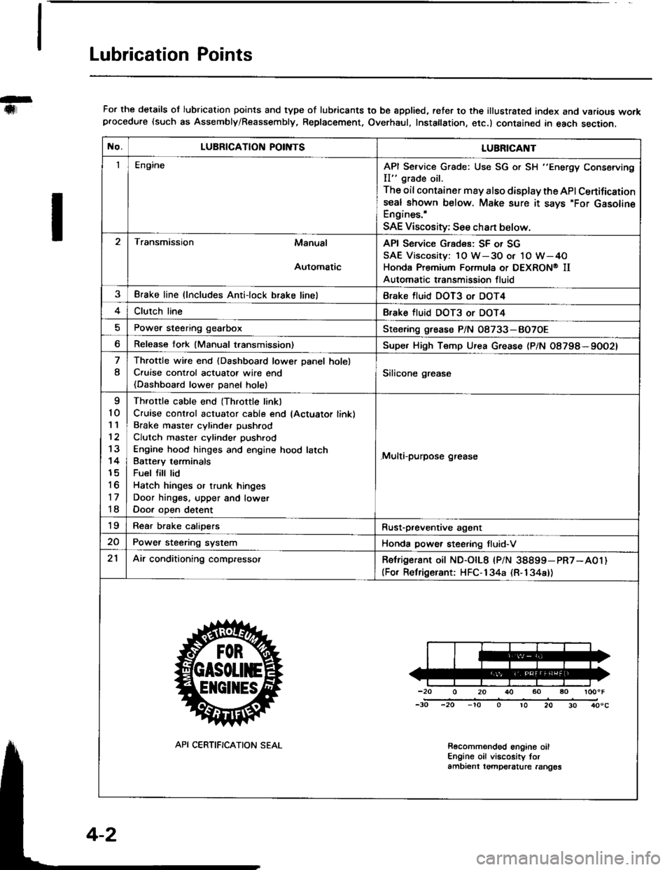
For the details ol lubrication points and type of lubricants to be spplied, reter to the illustrated index and various workprocedure (such as Assembly/Reassembly, Replacement, Overhaul, Instatlation, etc.) contained in each section.
No.LUBRICATION POII\ITSLUBRICAI\IT
IEngineAPI Service Grade: Use SG or SH "Energy Conserving
II" grade oil.
The oil container may also display the API Certifications€al shown below. Make sure it says'For GasolineEngines.'
SAE Viscosity; See chan below.
Transmission Manual
Automatic
API Service Grades: SF or SG
SAE Viscosity: 1O W-3O or 1O W-4O
Honda Premium Formula or DEXRON@ II
Automatic transmission fluid
3Brake line (lncludes Anti-lock brake linelBrake fluid DOT3 or DOT4
4Clutch lineBfake tluid DOT3 or DOT4
Power steering gearboxSteoring grease P/N 08733-BO7OE
Release fork (Manual transmission)Supe. High Temp Urea Grease (P/N O8798*9OO2)
8
Throttle wire end {Dashboard lower Danel holel
C.uise cont.ol actuatot wire end
{Dashboard lower Danel holel
Silicone grease
I
10'I '�l
12
13
14
15
to
17
18
Throttle cable end (Throttle linkl
Cruise control actuator cable end lActuator link)
Brake master cvlinder Dushrod
Clutch master cylinder pushrod
Engine hood hinges and engine hood latch
Batte.v terminals
Fuel fill lid
Hatch hinges or trunk hinges
Door hinges. upper and lowet
Door oDen detent
.Multi-purpose grease
19Rear brake calioersRust-p,eventive agant
20Power steering systemHonda power steering tluid-V
21Air conditioning compressorRetrigerant oit ND-otL8 |PlN 38899-pR7-A01)(For Relrigerant: HFC-134a (R-134a))
-20 0 20 r}() 60 ao loooF
-30 -20 -'to o 10 20 30 40"c
Recolnmendod engine oilEngine oil viscosity torambient tgmpelalure rangos
API CERTIFICATION SEAL
Page 48 of 1413
Engine Removal/lnstallation
@a Make sure jacks and safety stands aro placed ploper-
ly and hoisl brackots arg attachod to the correct po-
sitions on tho engine (se€ ssction 1).
a Mak€ sure tho car willnot roll off stands and tallwhile
you are wotking under it'
CAUTION:
a Use fendet covals to avoid damaging painted
sudaces.
r Unspecified itsms alo common
a Unplug tho widng connectots carefully while holding
the couplor and tha connector portion to avoid
oamage.
a Mark all wiring and hoses to avoid misconnection.
Also, be sulo that thsy do not contact other wiring
or hoses, or interfere with oth€l parts.
NOTE: Anti-theft radios have a coded theft ptotection
circuit. Be sure to get the customer's code number beJore
- Disconnecting the batterY.
- Removing the No. 32 (7.5 A) fuse from the under-
hood tuse/relay box.- Removing the radio
Atter service, reconnect power to the radio and turn it
on. When the word "CODE" is displayed, enter the cus-
tomer's 5-digit code to restore radio operataon.
1. Remove the hood (see section 2O).
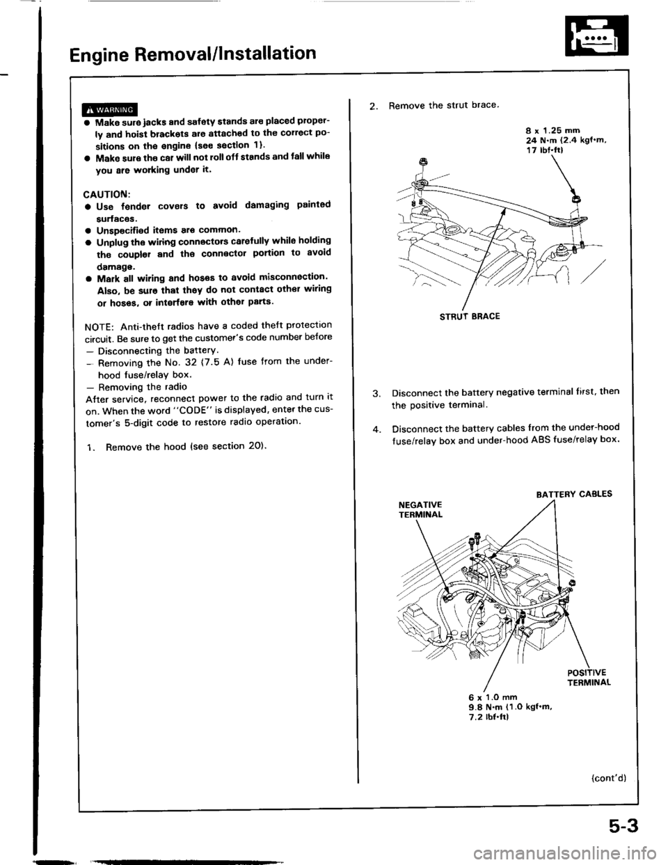
2. Remove the strut brace
8 x 1.25 mm24 N.m (2.4 kgf.m,17 rbt.ft)
Disconnect the battery negative terminal lirst. then
the positive terminal.
Disconnect the battery cables from the undel-hood
fuse/relay box and under-hood ABS fuse/relay box.
6 x l.O mm9.8 N.m (1 .O kgf'm,7.2 rbl.ftl
{cont'd)
STRUT ERACE
BATTERY CABLES
5-3
Page 78 of 1413
Gylinder Head
Removal
I
t
Engine removal is not required for this procedure.
CAUTION: To avoid damaging tho cylinder head, wait
until tho ongino coolant temporature drops bolow 100"F
{38"C) beforo loo36ning the rotainin0 bolts.
NOTE:
. Inspect the timing belt before removing the cylinder
neao.
. Turn the crankshaft pulley so that the No. 1 piston is
at top dead center (TDCI (page 6-12).
. Mark all emissions hoses before disconnecting them.. Anti-theft radios have a coded theft protection circuit.
Be sure to get the customer's code number before.- Disconnecting the battery.- Removing the No. 32 (7.5 A) fuse irom the under-
hood fuse/relay box.- Removing the radio.
After service, reconnect oower to the radio and turn it
on.
When the word "CODE" is displayed, enter the cus-
tomer's 5-digit code to restore radio operation.
1. Disconnect the negative terminalfrom the battery.
2. Drain the engine coolant (see page 10-5).
. Remove the radiator cap to speed draining.
3. Relieve fuel pressure (see Section 1 1).
@ Do not smoke whils working on tusl
systom, keep opon flame or spark away trom work
area. Drain fuol only inlo an approvod containsr.
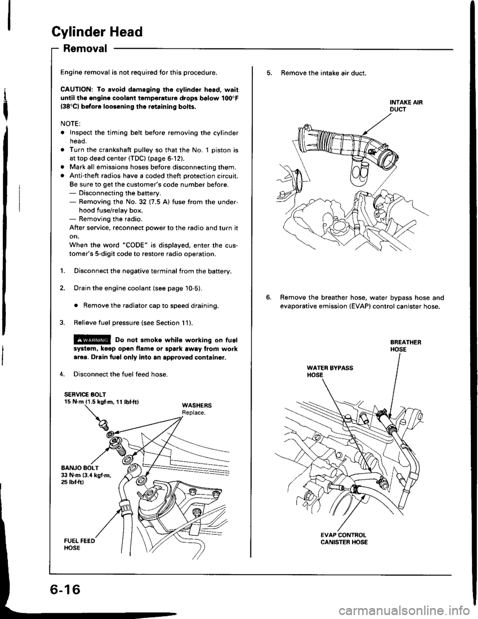
4. Disconnect the fuel feed hose.
SERVIC€ BOLT
WASHERSReplace.
5, Remove the intake air duct.
Remove the breather
evaporative emission
hose, water bypass hose and(EVAP) control canister hose.
Page 224 of 1413
Troubleshooting
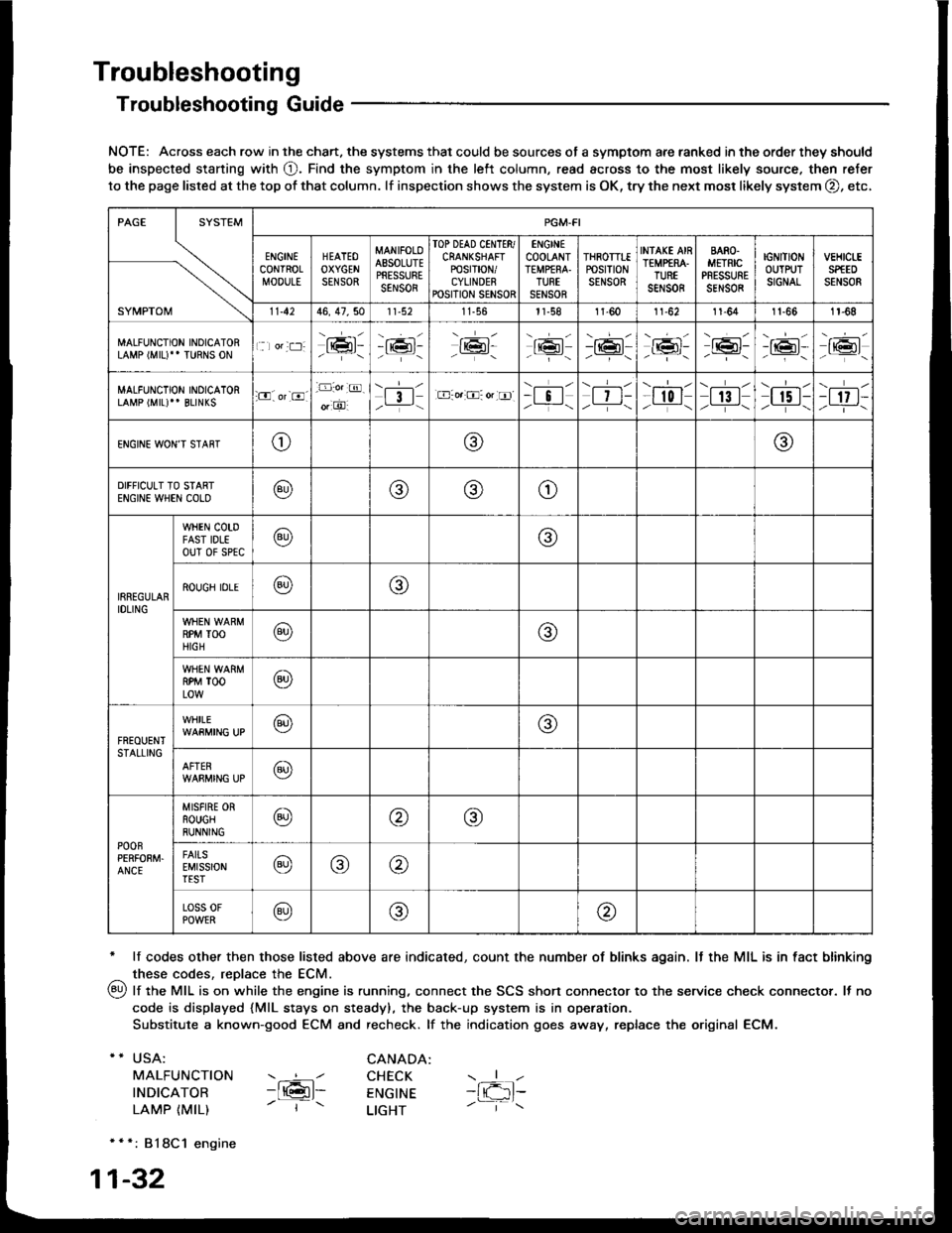
Troubleshooting Guide
NOTE: Across each row in the chart. the systems that could be sources of a symptom are ranked in the order they should
be inspected staning with O. Find the symptom in the left column, read across to the most likely source. then refer
to the page listed at the top of that column. lf inspection shows the system is OK, try the next mosr likely system O, etc,
* lf codes other then those listed above are indicated, count the number of blinks again. It the MIL is in fact blinking
^ these codes, replace the ECM.
qy, lf the MIL is on while the engine is running. connect the SCS shon connector to the service check connector. It no
code is displayed {MlL stays on steady), the back-up system is in operation.
Substitute a known-good ECM and recheck. lf the indication goes away, replace the original ECM.
USA:
MALFUNCTION
INDICATOR
LAMP {MIL)
CANADA: ----l CHECK-ltGl- ENGTNE- | - LTGHT
- { -1t-
* * *: 818C1 engine
1-32
SYMPTOM
PGM.FI
ENGINECONTROLMOOULE
HEATEOOXYGENSENSOR
MANIFOLOAESOLUTEPRESSURESENSOR
TOP DEAD CINTTR/CRANKSHAFTPOSTT|ON/CYLINDERPOSITION SENSOR
ENGINECOOLANTTEMPfRA.TURTSENSOR
THROTTTEPOStTtONSENSOR
INfAKE AIRTEMP€RA.TUREsar,rs0R
BARO.METRICPRESSURESENSOR
IGNITIONOUTPUTSIGNAL
vEHtct-ESPfEDSENSOR
11.4246, 47,5011-56l1-581l-6011-6211-641t-661r-68
MALFUNCTION INOICATORLAMP (MIU" TURNS ON1 lor:t:]:lrmr:- i;:i'-tK3t-16l-16l'-\-16l/-----\
-r:+r-
-{"Pr:-o_-16l-.z-\r6t/_-\
MALFUNCTION INOICATORLAMP (MIL)'' BLINKS:O. or-8.-D:o.:@.
o, O'l3l/__-\.E-o.:O: or tr]--i !l/ -i-\| 7 t-/__-\
--l-l-l r0 I/----\| 13 |z_---\
\.--r--l
I r5 t-/.---\-t 17 t-/-]-\
ENGINE WON'T STAffTo@@
DIFFICULT TO STARTENGIN€ WHEN COLO@@(9)o
IRREGULARIDLING
WHEN COTDFAST IDLEouT 0f sPtc@@
ROUGH IDLE@o
RPM TOOHIGH@@
RPM TOOLOW@
FREOUENTSTALLING
WHILE@@
AFTER@
POOnPERFOEM.ANCE
MISFIRE ORROUGHRUNNING@@@
FAITSEMISSIONTEST@@@
Loss 0FPOWER@@@
Page 289 of 1413
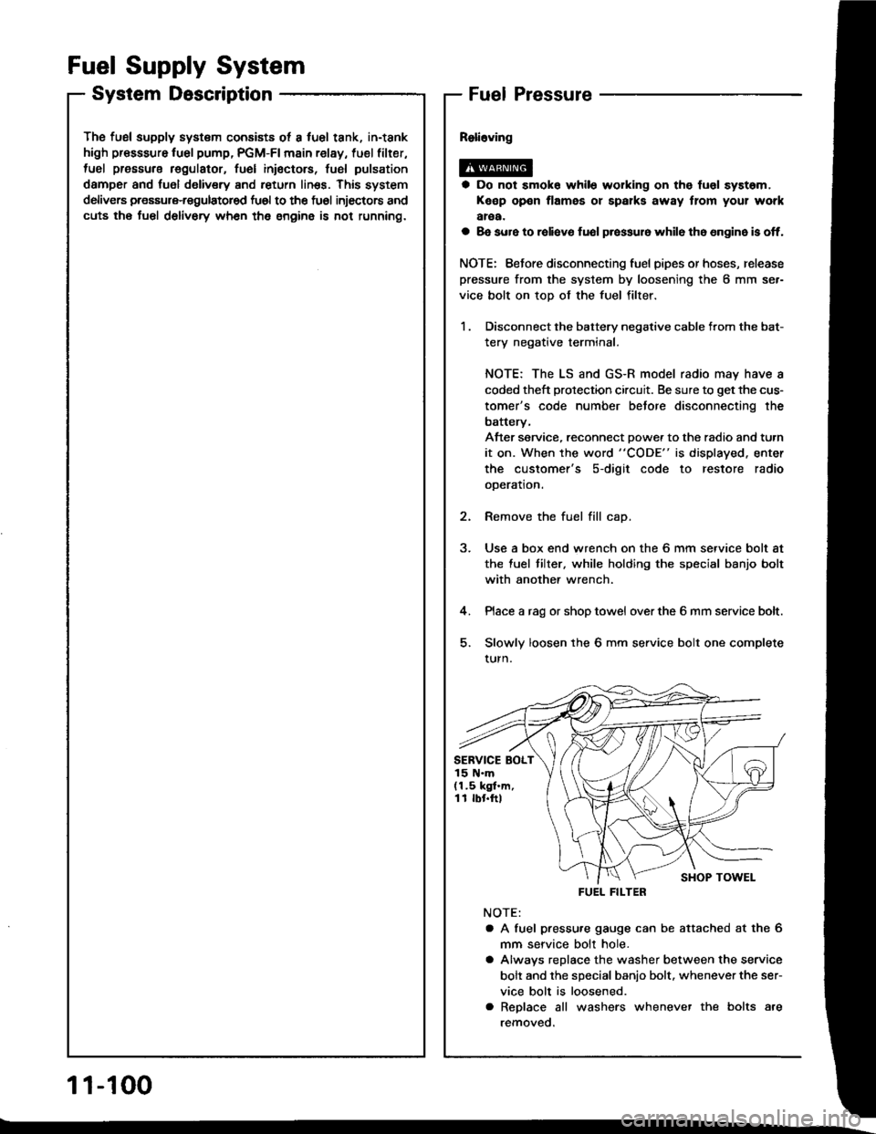
The fusl supply system consists ot a fuel tank, in-tank
high presssure fu6l pump, PGM-FI main relay, fuel filter,
tuel pressure regulatot, fuel inioctors, fusl pulsation
damper and fuol delivery and return linss. This system
delivers pressure-regulatored fu6l to the fu6l injectors and
cuts the fuel delivory wh6n the engine is not running.
Fuel Supply System
System DescriptionFuel Pressure
a Do not smok6 while working on the fuol syst6m,
Keep open flames or spalks away tlom your work
aroa.
a 8e sure to raliavo fuol p.essur6 while th6 6n9in6 is off.
NOTE: Eefore disconnecting fuel pipes or hoses, release
pressure from the system by loosening the 6 mm se.-
vice bolt on top of the fuel filter.
1 . Disconnect the battery negative cable from the bat-
tery negative terminal.
NOTE: The LS and GS-R model radio may have a
coded theft protection circuit. Be sure to get the cus-
tomer's code number betore disconnecting the
batterv,
After service, reconnect Dowe. to the radio and turn
it on. When the word "CODE" is displayed. enter
the customer's s-digit code to restore radio
ooeration.
2. Remove the fuel fill cap.
3. Use a box end wrench on the 6 mm service bolt at
the fuel tilter, while holding the special banjo bolt
with another wrench.
4. Place a rag or shop towel over the 6 mm service bolt.
5. Slowly loosen the 6 mm service bolt one complete
turn.
NOTE:
a A fuel pressu.e gauge can be attached at the 6
mm seryice bolt hole.
a Alwavs replace the washer between the service
bolt and the special banio bolt. whenever the ser-
vice bolt is loosened.
a Replace all washers whenever the bolts are
removeo.
SERVICE BOLT15 N.m(1.5 kgf.m,11 rbr.ftl
FUEL FILTER
1 1-100
Page 443 of 1413
Number of @indicator light
blinks while
Service Check
Connector is
connected with
the special tool.
@ indicator
lightPossible CauseSymptomRefer to
page
'loBlinksDisconnected engine coolant tempera-
rure (ECT) sensor connector
Short or open in ECT sensor wire
Faulty ECT sensor
Lock-up clutch does not
engage.14-68
1lOFFDisconnected ignition coil connector
Short or open in ignition coil wire
Faulty ignition coil
. Lock-up clutch does not
engage.'t 4-7 0
13Blinks. Shon or open in LT GRN wire between
the D3 terminal and ECM. Faulty barometric pressure {BARO)
sensor
NOTE: The BARO sensor is built into
the ECM
. No specific symptom
appears.
14-7 1
14Blinks. Short of open in FAS {YEL} wire be-
tween the D16 terminal and ECM. Faulty ECM
. Transmission jerks hard
when shitting.
't5OFFDisconnected mainshaft speed sensor
connecror
Short or open in mainshaft speed sen-
sor wire
Faulty mainshaft speed sensor
. Transmission jerks hard
when shifting.
14-75
SymptomProbable CauseRet.page
LQ! indicator light is on steady, not blinking whenever the ignition is on.14-77
[Q3] indicator light does not come on for 2 seconds after ignition is first
turned on.14-78
Lock-up clutch does not have duty operation (ON-OFFI.Check A/C signal with
A/C on.14-80Lock-up clutch does not engage.
Shitt leve. cannot be moved lrom @ position with the brake pedal
depressed.Check brake switch signal,14-41
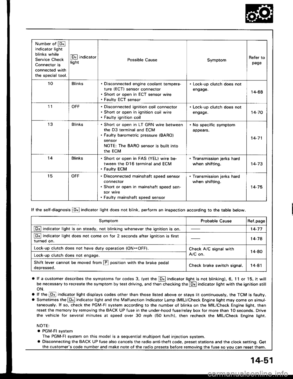
It the self-diagnosis LQ4 indicator light does not blink, perform an inspection according to the table below.
a lf a customer describes the symptoms for codes 3, (yet the LQ! indicator light is not blinkingl, 6, 1 1 or 15, it will
be necessa.y to recreate the symptom by test driving. and then checking the @ indicator light with the ignition still
oN.
e lt ttre @ indicator light displays codes olher than those listed above or stays lit continuously, the TCM is faulty.. Sometimes the Lqd indicator light and the Malfunction Indicator Lamp (MlL)/Check Engine light may come on simul-taneously. lf so, check the PGM-Fl system according to the numbe. of blinks on the MIL/Check Engine light. thenreset the memory by removing the BACK UP fuse in the unde.-hood fuse/relay box for more than 1O seconds. Drive
the vehicle for several minutes at speed over 30 mph (5O km/h), then recheck the MIL/Check Engine light.
NOTE:
. PGM-FI system
The PGM-Fl system on this model is a sequential multiport fuel injection system.a Disconnecting the BACK UP luse also cancels the radio anti-theft code. preset stations and the clock setting. Get
the fuse so vou can reset them.the customer's code number and make note ot the radio
14-51
Page 608 of 1413
Steering
Special Tools ............. 17-2
Component Location
lndex ................ ...... 17-3
System Description
Ff uid Flow Diagram ......................... 17 -1
Steering Pump ................................. 17-5
Steering Gearbox ............................. 17-7
Troubleshooting
General Troubleshooting ................ 17-10
Noise and Vibration ......................... 17-14
Fluid Leaks ............. 17-16
Inspection and Adiustment
Steoring Operation .......................... 17 -14
Power Assist Check
with Car Parked ........................... 17-18
Steering Linkage and Gearbox ....... 17-19
Pump Beh .............. 17-20
Rack Guide Adjustment ............. ..... 17-21
Ff uid Replacement ...................... ..... 17 -21
Pump Pressure Check .................. .... 17 -22
Ffuid Leakage lnspection ................ 17-23
+ Steering Wheel
Removal ..,,,,,,,........ 17-24
Disassembly/Reassembly ............... 17 -25
fnstallation ,......,,,,,. 17-26
* Steering Column
Removaf .................17-28
Inspection .............. 17-30
Installation ............. 17-31
Power Steering Hoses. Pipes
Replacemont ......... 17-3tl
Power Steering Pump
Removal ................. 17-35
Disassembly .......... 17-35
Reassembly ........... 17-'10
lnstallation ........,..., l7-tltl
Steering Gearbox
Removaf .,.,............. 17-45
Disassembly .......... 17-/E
Reassembly ........... 17-53
lnstallation ............. 17-63
Ball Joint Boot Replacement .......... 17-65
SUPPLEMENTAL RESTRAINT SYSTEM {SRSI
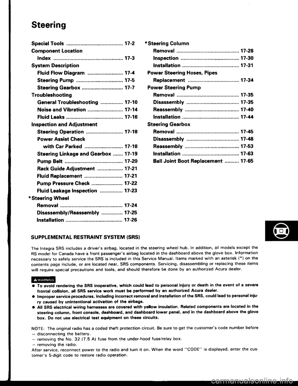
The Integra SRS includes a driver's airbag. located in the steering wheel hub, In addition, all models except the
RS model for Canada have a front passenger's airbag located in the dashboard above the glove box. Information
necessarv to safely service the SRS is included in this Service Manual. ltems marked with an asterisk {') on the
contents page include, or are located near, SRS components. Servicing. disassembling or replacing these items
will require special precautions and tools, and should therefore be done by an authorized Acura dealer.
a To avoid rsndering ths SRS inoporative, which could load to po.sonal iniury 01 d€ath in th€ event ot a ssvare
lrontal collision, all SRS service work muat be performod by an authorizod Acura deal6t.
a lmploper service procodules. including incorloct romoval and installation of the SRS, could lead to personal iniu-
ry caused by unintontional activation ot the airbags.
a All SRS elsctdcal wiring harnesses ara covorod with ysllow insulation. Rolalod compon€nts 8re locatsd in tho
stse ng column, tront console, dashboard, and dashboard lower panel, and in the dashboard above the glove
box. Do not use oloctrical tost equipmoni on thosa cilcuits.
NOTE: The original radio has a coded thett protection circuit. Be sure to get the customer's code number before
- disconnecting the battery.- removing the No. 32 (7.5 A) tuse from the under-hood fuse/relay box.
- removing the radio.
Alter service, reconnect power to the radio and turn it on. When the word "CODE" is displayed' enter the cus-
tomer's 5-digit code to restore radio operation.
Page 1001 of 1413
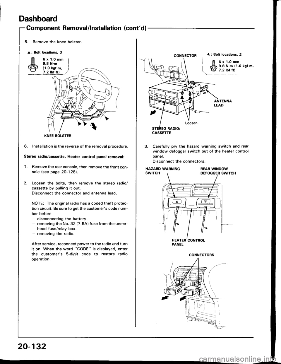
Dashboard
Component Removal/lnstallation (cont'dl
5. Remove the knee bolster.
: Bolt locations, 3
fi 6rt.omm
6 i;i'i#.,7.2 tbr.ftl
?
KNEE
6. Installation is the reverse of the removal Drocedure.
Stol€o radio/cassette, Heater control panal removal:
1 . Remove the rear console, then remove the front con-
sole (see page 20-128).
Loosen the bolts, then remove the stereo radio/
cassette by pulling it out.
Disconnect the connector and antenna lead.
NOTE: The original radio has a coded theft protec-
tion circuit, Be sure to get the customer's code num-
ber belore- disconnecting the battery.
removing the No. 32 17.5A) fuse from the under-
hood fuse/relay box.- removing the radio.
After service, reconnect power to the radio and turn
i1 on. When the word "CODE" is displayed. enter
the customer's 5-digit code to restore radio
operation.
20-132
CONNECTOR
CASSETTE
i Bolt locations. 2
6 x 1.0 mm9.8 N.m {1.0 kgl.m,
3, Carefully pry the hazard warning switch and rear
window defogger switch out of the heater control
Daner.
Disconnect the connectors.
HAZARD WARNINGswtTcHREAR WINOOWDEFOGGER SWITCH
Page 1005 of 1413
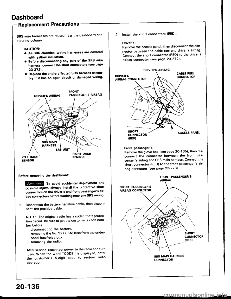
Dashboard
Replacement Precautions
SRS wife harnesses are routed near the dashboard and
steering column.
CAUTION:
a Alt SRS olectrical wiling harness€s ale covorad
with Yollow insulation.
a Botore disconnecting any part ot the SRS wiro
harness, connect ths short connscto6 (see page
23-2721.
a Roplac6 ih€ entiro aflectod SRS halnoss assem-
bly il it has an opon cilcuit or damagod wiling'
LEFT DASHSENSOR
Bstora lomoving the dashboaid:
!@@ To avord accioenlal dsployment and
""iUU inir.v, always install the plotoctive short
;onnectors on the driver's and tlont pass€ngel's air-
bag connectors bolors working near any SRS wiring'
1. Disconnect the battery negative cable, then discon-
necl the positive cable.
NOTE: The original radio has a coded theft protec
tion circuit. Be sure to get the customer's code num-
ber before- disconnecting the battery.
- removing the No 32 (7.5A) Iuse from the under-
hood fuse/relaY box'- removing the radio.
After service, reconnect power to the radio and turn
it on. When the word "CODE" is displayed, enter
the customer's 5 digit code to restore radlo
ooeration.
DRIVER'S AIREAG
SRS UNIT
20-136
DRIVER'S AIRBAG
2.lnstall the short connectors (RED)
Ddvar's:
Remove the access panel, then disconnect the con-
nector between the cable reel and driver's airbag'
Connect the short connector (RED) to the driver's
airbag connector lsee page 23-27 2l'
DRIVER'SAIRBAG CONNECTOB
CABLE REELCONNECTOR
SHORTCONNECTOR(RED)
Front passongor's:
Remove the glove box {see page 20-135}, then dis-
connect the connector between the tront pas'
senger's airbag and SRS main harness Connect the
short connector (RED) to the front passenger's air-
bag connector (see Page 23-273).
FROf{T PASSENGER'SAIRBAG
ACCESS PAI{EL
FRONT PASSET{GER'SAIRBAG CONNECTON
SHORTCONNECTOR(REDI
SBS MAIN HARNESS
CONNECTOR