ground clearance HONDA INTEGRA 1994 4.G Workshop Manual
[x] Cancel search | Manufacturer: HONDA, Model Year: 1994, Model line: INTEGRA, Model: HONDA INTEGRA 1994 4.GPages: 1413, PDF Size: 37.94 MB
Page 26 of 1413

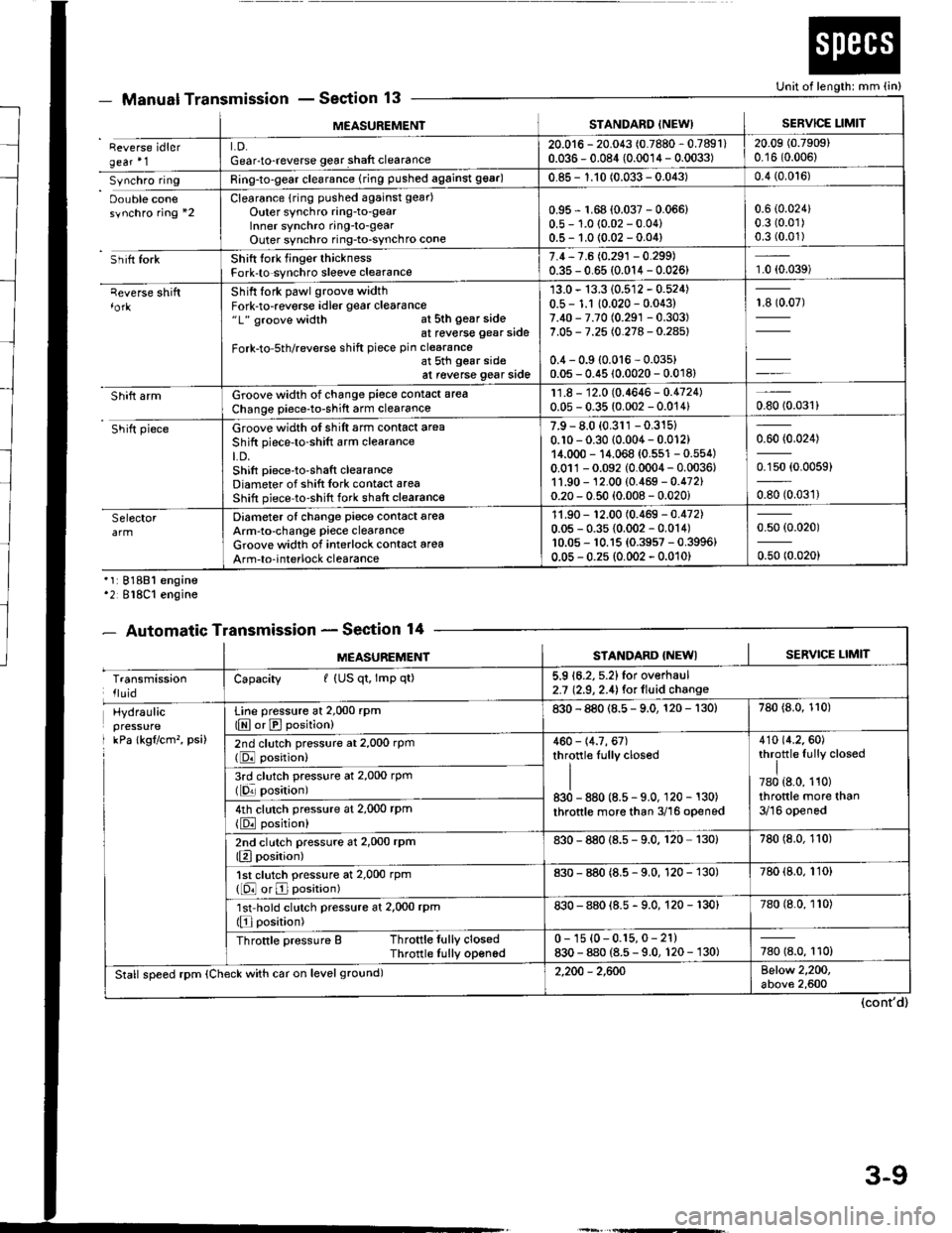
MEASUREMENISTANDARD INEW)SERVICE LIMIT
Reverse idlergear'1LD.Gear-to-reverse gear shaft clearance20.016 - 20.043 (0.7880 - 0.7891)0.036 - 0.084 (0.0014 - 0.0033)20.09 (0.7909)
0.16 (0.006)
Synchro ringRing-to-gear clearance (ring pushed against 99ar)0.85 - 1.10 (0.033 - 0.043)0.4 (0.0't6)
Oouble conesynchro ring *2Clearance {rin9 pushed against gear)
Outer synchro ring-to-gearlnner synchro ring-to-gearOuter synchro ring-to-synchro cone
0.95 r 1.68 (0.037 - 0.066)0.5 - 1.0 (0.02 - 0.04)0.5- 1.0 {0.02 -0.04)
0.6 (0.024)
0.3 (0.01)
0.3 (0.01)
Sh itt forkShift tork finger thicknessFork-to synchro sleeve clearance7.4,7.6 (0.291 - 0.299)0.35 - 0.65 (0.014 - 0.026)1.0 (0.039)
qeverse shiftShift fork pawl groove widthFork-to-reverse idler gear clearance"1" groove width at sth gear sideat reverse gear side
Fork-to-5th/reverse shift piece pin clearanceat 5th gear sideat reverse gear side
13.0 - 13.3 (0.512 - 0.524)0.5 - 1.1 10.020 - 0.043)7.40 - 7.70 (0.291 -0.303)
7.05 - 7.25 (0.278 - 0.28s)
0.4 - 0.9 {0.016 - 0.03s)0.05 - 0.45 (0.0020 - 0.018)
13907)
Shift armGroove width of change piece contact area
Change piece-to-shift arm clearance11.8 - 12.0 (0.4646- 0.4724)0.05 - 0.35 (0.002 - 0.014)0.8010.031)
Shift pieceGroove width of shift arm contact area
Shift piece'to-shift arm clearanceLD.Shift piece-to-shaft clearanceDiameter of shift Iork cont6ct areaShift piece-to-shift fork shaft clearance
7.9 - 8.0 (0.311 -0.315)
0.10 - 0.30 (0.004 - 0.012)14.000 - 14.068 {0.551 - 0.554)0.011-0.092 (0.0004 - 0.0036,1'1.90 - 12.00 (0.469 - 0.472)0.20 - 0.50 (0.008 - 0.020i
0.60 (0.024)
0.150 (0.0059)
oso to.oart
SelectorDiameter of change piece contact areaArm-to-change piece clearanceGroove widlh of interlock contact area
Arm-to-interlock clearance
11.90 - '�t2.00 (0.469 - 0.472)0.05 - 0.35 {0.002 - 0.014)10.05 - 10.15 {0.3957 - 0.3996}0.05 - 0.2s (0.002 - 0.010)
0.50 (0.020)
0.50 (0.020)
Manual TransmissionSection 13
'1:81881 engine'2 818C1 engine
- Automatic TransmissionSection 14
Unit of length: mm (in)
(cont'd)
- oEutrlrrl rr
MEASUREMENTSTANDARD {NEWISERVICE LIMIT
TransmissionlluidCapacity I (US qt, lmp qt)5.9 16.2, 5.2)for overhaul2.7 (2.9, 2.4) for lluid change
Hydraulicpressure
I kPa lkgflcm'�, psi)
Line pressure at 2,000 rpm(E or E position)830 - 880 (8.5 - 9.0, 120 - 130)780 {8.0, 110)
2nd clutch pressure at 2,000 rpm(DJ position)460 - 14.7, 67)throttle Iully closed
II830 - 880 (8.5 - 9.0, 120 - 130)
throttle more than 3/16 opened
410 {4.2.60)throttle fully closed
I780 {8.0, 110)throttle more than3/16 opened
3rd clutch pressure at 2,000 rpm(lqr posirion)
4th clutch pressure at 2,000 rPm
{E position)
2nd clutch pressure at 2,000 rPm(Elposition)830 - 880 {8.s - 9.0. 120 130)780 (8.0, 110)
1st clutch pressure at 2,000 rpm([O or E position)830 - 880 (8.5 - 9.0, 120 - 130)780 (8.0, 110)
'lst'hold clutch pressure at 2,000 rpm(Elposition)830 - 880 {8.5 - 9.0, 120 - 130}780 (8.0, 110)
Throttle pressure B Throttle fully closedThrotlle Iully opened0 - 1s {0-0.15,0- 21)830 - 880 (8.5 - 9.0, 120 - 130)780 18.0, 110)
Stall speed rpm (Check with car on level ground)2,200 - 2,600Below 2,200,above 2,600
3-9
Page 34 of 1413
![HONDA INTEGRA 1994 4.G Workshop Manual Design Specifications
]TEMMETRICENGLISHNOIES
: vENSTONSOveralllength 3 DOOR
4 DOOR
Ov€rallWidth
Overall Height 3 DOOR
4 DOOR
Wheelbase 3 DOOR
4 DOOR
Track F/R
Ground Clearance
Seating Capacity
4.38 HONDA INTEGRA 1994 4.G Workshop Manual Design Specifications
]TEMMETRICENGLISHNOIES
: vENSTONSOveralllength 3 DOOR
4 DOOR
Ov€rallWidth
Overall Height 3 DOOR
4 DOOR
Wheelbase 3 DOOR
4 DOOR
Track F/R
Ground Clearance
Seating Capacity
4.38](/img/13/6067/w960_6067-33.png)
Design Specifications
]TEMMETRICENGLISHNOIES
:' vENSTONSOveralllength 3 DOOR
4 DOOR
Ov€rallWidth
Overall Height 3 DOOR
4 DOOR
Wheelbase 3 DOOR
4 DOOR
Track F/R
Ground Clearance
Seating Capacity
4.380 mm
4.525 mm
'1,710 mm
1,335 mm
1,370 mm
2,570 mm
2,620 mm
't,475/1,470 mm
150 mm
Four (3 DOOR)
172.1in
178.1 in
67.3 in
52.6 in
101.2 in
103.1 in
5|8.1/57.9 in
Five (4 DOOR)
,rerght (usA)cross V€hicle Weight Rating {GVWR)3,680lbs
'le,ght {CANADA)Gross Vehicls Weight Rating {GVWR)1,670 kg
:\GINEType81881 engine
818C1 engine
Cylinder Arrangement
Bore and Stroke
Displacement
Compression Ratio
81881
818C1
81881
B18C I
81881
B 18C1
81881
818C1
engrne
engane
engrne
engine
engine
engine
engine
engine
L!brication Systom
OilPump Displacement
Wster Pump Displacement
FuelRequired
81881
B18C 1
81881
B 18C1
91881
engrne
engrne
engine
engine
engine
818C1 engine
Water-cooled, 4-stroke DOHC
gasoline engine
Watercooled, 4-stroke DOHC
VTEC gasoline engine
Inline 4-cylinder, transverse
81.0 x 89.0 mm
81.0 x 87.2 mm
1,834 cm3 (mf )
1,797 cm3 (m{)
3.19 x 3.50 in
3.19 x 3.43 in
112 cu-in
110 cu-in
9.2:1
10.0 : 1
Eelt driven, OOHC 4 valve per cylinder
Belt driven, DOHC VTEC
4 valve per cylinder
Forced and wet sump, trochoid pump
50, {53 US qt, 44 lmp qt)/minute'l
71 f {75 US qt, 62 lmp qt)/minute"
140 f (148 US qt, 123 lmp qt)/minute*!
140 f (148 US qt. 123 lmp qt)/minute*'
UNLEADED gasoline with 86 Pump
Octane Numb€r or higher
Premium UNLEADED gasoline wilh
91 Pump Octane Number or higher
STARTERTypo
NormalOutput
NominalVoltage
Hour Rating
Direction of Rotation
Weight
Gear reduction
1.4 kW
12V
30 seconds
Clockwise as viewed lrom g6ar end
3.7 k9 | 8.3lbs
CLUTCHClutch Type
Clutch Facing Area
M/TSingle plate dry, diaphragm spring
Torq!e converter
203 cm'� I 31 sq-in
TRANSMISSIONTransmission Type M/T
Primary Reduction
Synchronized 5-speed forward, 1 reverse
Electronically controlled
4-speed automatic. 1 rcverse
Diract 1 : 1
'1: At 6,000 engine
'2: At 7,600 engine
rpm
rpm
(cont'd)
3-17
Page 1249 of 1413

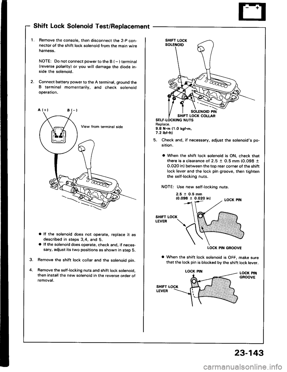
Shift Lock Solenoid Test/Replacement
Remove the console, then disconnect the 2-p con-neclor oJ the shift lock solenoid from the main wireharness.
NOTE: Do not connect powe. to the B { - ) terminat(reverse polarity) or you will damsge the diode in-side the solenoid.
Connect battery power to the A terminal, ground theB terminal momentarily. and check solenoidoDeralron.
a lf the solenoid does not operate, replace it asdescribed in steps 3,4, and 5.a lJ the solenoid does operate, check and, if neces-sary, adiust its two positions as shown in step 5.
Remove the shift lock collar and the solenoid pin.
Remove the selflocking nuts and shift lock solenoid,then installthe new solenoid in the reverse otder otremovat.
a
Replace.9,8 N.m {1.0 kgl.m,7.2 tbl.hl
5. Check and, if necessary, adjust the solenoid's po-
sition.
a When the shift lock solenoid is ON, check that
there is a clearance ol 2.5 1 O.5 mm {O.O98 I
O.O2O in) between the toD rear corner ot the shift
lock lever 8nd the lock pin groove, then tighten
the selflocking nuts.
NOTE: Use new self-locking nuts.
2.5 t O.5 mm{0.098 t 0.020 inl
SHIFTLEVEB
LOCK PIN GROOVE
a When the shift lock solenoid is OFF, make surethat the lock pin is blocked bv the shift lock lever.
LOCK PINGROOVE
LOCK
LOCK PIN
23-143