ESP HONDA INTEGRA 1994 4.G Workshop Manual
[x] Cancel search | Manufacturer: HONDA, Model Year: 1994, Model line: INTEGRA, Model: HONDA INTEGRA 1994 4.GPages: 1413, PDF Size: 37.94 MB
Page 3 of 1413
INTRODUCTION
How to Use This Manual
This manual is divided into 23 sections. The first page of each sec-
tion is marked with a black tab that lines up with its corresponding
thumb index tab on this page and the back cover. You can quickly
tind the tirst page of each section without looking through a full ta-
ble of contents. The svmbols printed at the top corner of each page
can also be used as a quick reference system.
Each section includes:
1. A table of contents. or an exploded view index showing:
a Parts disassemblv sequence.
a Bolt toroues and thread sizes.
a Page references to descriptions in text.
2. Disassemblv/assembly procedures and tools.
3. InsDection.
4. Testing/troubleshooting.
5. Repair.
6. Adiustments.
Special Information
@ lnai""tes a strong possibility of sevor€ pelsonal iniury
01 loss of life it instructions al€ not tollowed.
CAUTION: Indicates a possibility ot personal inlury or oquipmont
damage if instructions ale not followed.
NOTE: Gives helpful information.
CAUTfON: Detaifed doscriptions ot standad workshop procedures,
salety principlos and servica opelations are not included Pleaso note
that this manual conlains warnings and cautions against somo spocif-
ic sgrvice methods which could cause PERSONAL INJURY, damage
a vehicle or make it unsafe. Pleaso understand that those warnings
cannot cover all conceivablc waYs in which service, whethea or not
recommended bv HONDA, might be done, or of the possibla
hazardous consequences of svery conceivable way, nor could
HONDA investigate all such ways. Anyone using seryice plocedures
or toofa, whethor 01 not recomonded by HONDA, ,nust sttisfY him-
sett thoroughly that neither personal saf€ty nor v€hicle safety will
be jaopaldized.
All information contained in this manual is based on the latest product
information available at the time of printing. We reserve the right
to make changes at any time without notice. No part of this publica-
tion mav be reproduced, stored in retrieval system, or transmitted,
in any Jorm by any means, electronic, mechanical, photocopying,
recording, or otherwise, without the prior written permission of the
publisher. This includes test. figures and tables.
Specificationstrtl:{lt'
Maintenance4Pi
Engine
H
I-""
Fuel and Emissions Za
*Transaxle
*Steeringr-\
lDl\.t/
* Brakes
(lncludins !TEg)o
*Electrical J--*
(lncludins ISBE)
First Edition 7/93 1448 pages
All Rights Reserved
Specifications Apply to U.S.A. and Canada
HONDA MOTOR CO.,LTD,
Service Publication ottice
As sections with r includ€ SRS components.
special precautions are lequiled when servicing.
Page 69 of 1413
-
'14.
Valve Seals
Replacement (cylinder head removal not required) (cont'dl
'11.Using a downward motion on the lever arm. com-press the valve spring and remove the keepers from
the valve stem. Slowly release pressure on the
spring.
Repeat step l1 for the other valve in that cylinder.
Remove the valve seals (see page 6-22).
Installthe valve seals (see page 6-23).
Install the springs, the retainers and the keepers in
reverse order of removal.
16. Repeat steps 9 to l5 for the other three cylinders.
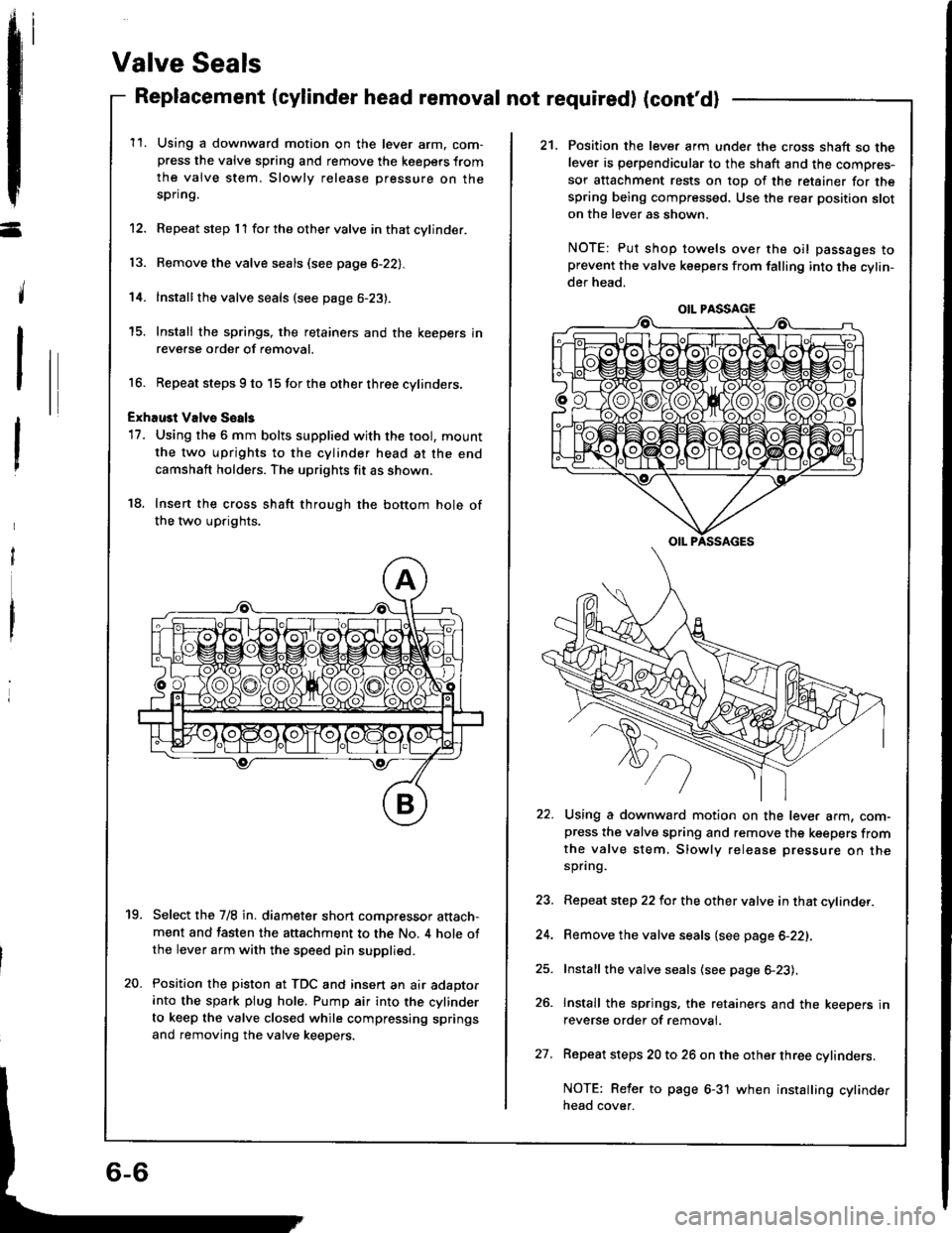
ExhaGt Valvs Soals
17. Using the 6 mm bolts supplied with the tool, mount
the two uprights to the cylinder head at the end
camshaft holders. The uprights fit as shown.
18. Insert the cross shaft through the bottom hole of
the two uprights.
Select the 7/8 in. diameter short compressor attach-ment and fasten the attachment to the No. 4 hole ofthe lever arm with the speed pin supplied.
Position the piston at TDC and insert an air adaptorinto the spark plug hole. Pump air into the cylinder
to keep the valve closed while compressing springs
and removing the valve keepers.
19.
20.
21. Position the lever arm unde. the cross shaft so thelever is perpendicular to the shaft and the compres-
sor attachment rests on top of the retainer for thespring being compressed. Use the rear position sloton the lever as shown.
NOTE: Put shop towels over the oil passages toprevent the valve keepers from falling into the cylin-der head.
Using a downward motion on the lever arm, com-press the valve spring and remove the keepers fromthe valve stem. Slowly release pressure on thespring.
Repeat step 22 for the other valve in that cylinder.
Remove the valve seals (see page 6-22).
Install the valve seals (see page 6-23).
Install the springs, the retainers and the keepers inreverse order of removal.
Repeat steps 20 to 26 on the other three cylinders.
NOTE: Reler to page 6-31 when installing cylinderneao cover.
OIL PASSAGE
27.
Page 100 of 1413
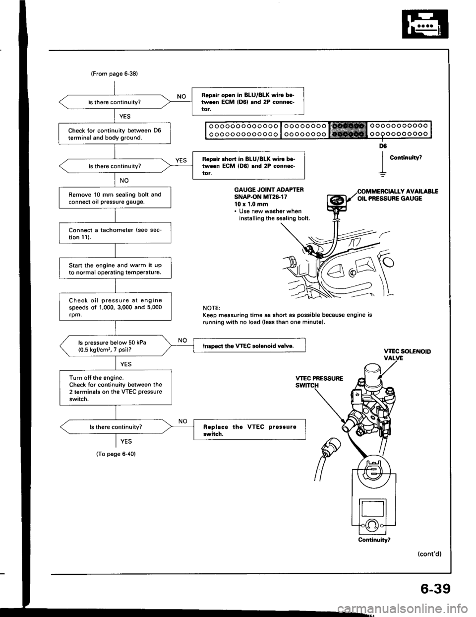
(From page 6-38)
Ropair op€n in BLU/BLK $,iro between ECM lD6) and 2P conn.c-tor,
Check for continuity between D6terminal and body ground.
R6pri. short in BLU/BLK wir. bc-tweon ECM (D6l .nd 2P connec-toa,
Remove 10 mm sealing bolt andconnect orl pressure gauge.
Connect a tachometer {soe sec-tion 11).
Start the engine and warm it upto normal operatrng temperature.
Check oil pressure at enginespeeds of 1,000, 3,000 and 5,000rpm,
ls pressure bolow 50 kPa(0.5 kgflcm'�, 7 psi)?Inrpoct tho VTEC aolanoid v.lv..
Turn off the engine.Check lor continuity between the2 terminals on the VTEC pressure
switch.
o oooooo ooo ooo I oooooooo trt!*Hffi Oooooo ooooo
o oooo ooooo ooo I oo oooo ooo ooooo oo oo o
Coitlnuity?
D6
I
GAUGE JOINT ADAPTERSNAPON MT2&1710 x 1.0 mm. lJse new washer wheninstalling the sealing bolt.
Y AVAILAEIIOIL PRESSURE GAUGE
\-
]L
vtEc sot-€NotD
(cont'd)
NOTE:Keep mgasuring time as short as possible bocaus€ engine isrunning with no load (less than one minute).
YES
(To page 6-40)
Conlinuity?
6-39
Page 130 of 1413
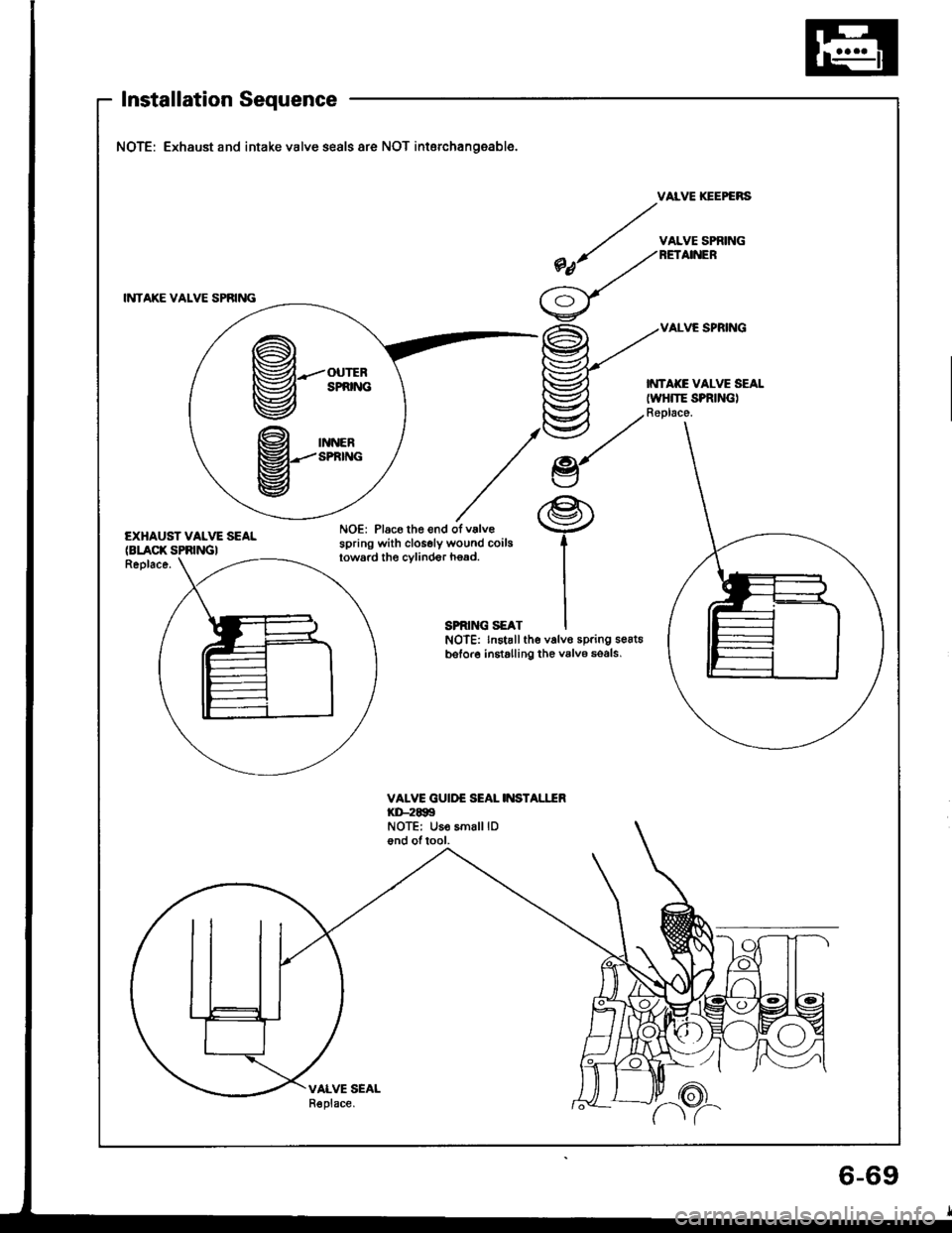
Installation Sequence
NOTE: Exhaust and intake valve seals are NOT interchangeable.
VAIVE IGEPGNS
INTAKE VALVE SPAING
/ v^LvEsP'ittNG
*nt /^no,n
/'=\/\y
VALVE SPRING
EXHAUST VALVE SEALNOE: Place the end ofv.lv€spring with closely wound coilgloward the cvlinder h€ad.(BLACK SPRINGIReplace.
SPRING SEATNOTE: lnstallthe valvo spring se6t6bsfore installing the valv6 so6ls,
VALVE GUIDE SEAL II{STALITRKD-2EgSNOTE: Uso smalllDond oftool.
VALVE SEALR€place.
@--'**
9-**
P.%
6-69
Page 224 of 1413
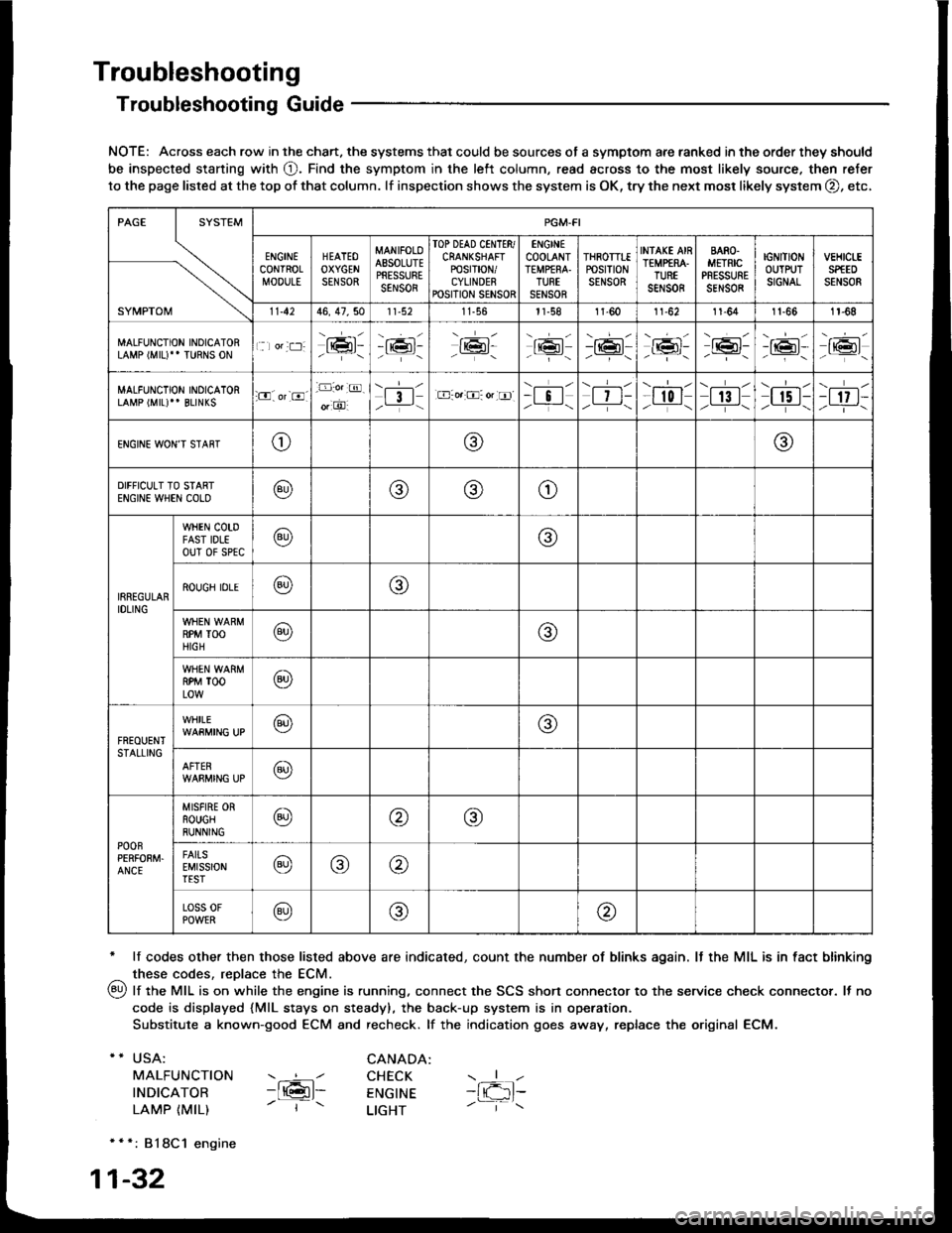
Troubleshooting
Troubleshooting Guide
NOTE: Across each row in the chart. the systems that could be sources of a symptom are ranked in the order they should
be inspected staning with O. Find the symptom in the left column, read across to the most likely source. then refer
to the page listed at the top of that column. lf inspection shows the system is OK, try the next mosr likely system O, etc,
* lf codes other then those listed above are indicated, count the number of blinks again. It the MIL is in fact blinking
^ these codes, replace the ECM.
qy, lf the MIL is on while the engine is running. connect the SCS shon connector to the service check connector. It no
code is displayed {MlL stays on steady), the back-up system is in operation.
Substitute a known-good ECM and recheck. lf the indication goes away, replace the original ECM.
USA:
MALFUNCTION
INDICATOR
LAMP {MIL)
CANADA: ----l CHECK-ltGl- ENGTNE- | - LTGHT
- { -1t-
* * *: 818C1 engine
1-32
SYMPTOM
PGM.FI
ENGINECONTROLMOOULE
HEATEOOXYGENSENSOR
MANIFOLOAESOLUTEPRESSURESENSOR
TOP DEAD CINTTR/CRANKSHAFTPOSTT|ON/CYLINDERPOSITION SENSOR
ENGINECOOLANTTEMPfRA.TURTSENSOR
THROTTTEPOStTtONSENSOR
INfAKE AIRTEMP€RA.TUREsar,rs0R
BARO.METRICPRESSURESENSOR
IGNITIONOUTPUTSIGNAL
vEHtct-ESPfEDSENSOR
11.4246, 47,5011-56l1-581l-6011-6211-641t-661r-68
MALFUNCTION INOICATORLAMP (MIU" TURNS ON1 lor:t:]:lrmr:- i;:i'-tK3t-16l-16l'-\-16l/-----\
-r:+r-
-{"Pr:-o_-16l-.z-\r6t/_-\
MALFUNCTION INOICATORLAMP (MIL)'' BLINKS:O. or-8.-D:o.:@.
o, O'l3l/__-\.E-o.:O: or tr]--i !l/ -i-\| 7 t-/__-\
--l-l-l r0 I/----\| 13 |z_---\
\.--r--l
I r5 t-/.---\-t 17 t-/-]-\
ENGINE WON'T STAffTo@@
DIFFICULT TO STARTENGIN€ WHEN COLO@@(9)o
IRREGULARIDLING
WHEN COTDFAST IDLEouT 0f sPtc@@
ROUGH IDLE@o
RPM TOOHIGH@@
RPM TOOLOW@
FREOUENTSTALLING
WHILE@@
AFTER@
POOnPERFOEM.ANCE
MISFIRE ORROUGHRUNNING@@@
FAITSEMISSIONTEST@@@
Loss 0FPOWER@@@
Page 268 of 1413
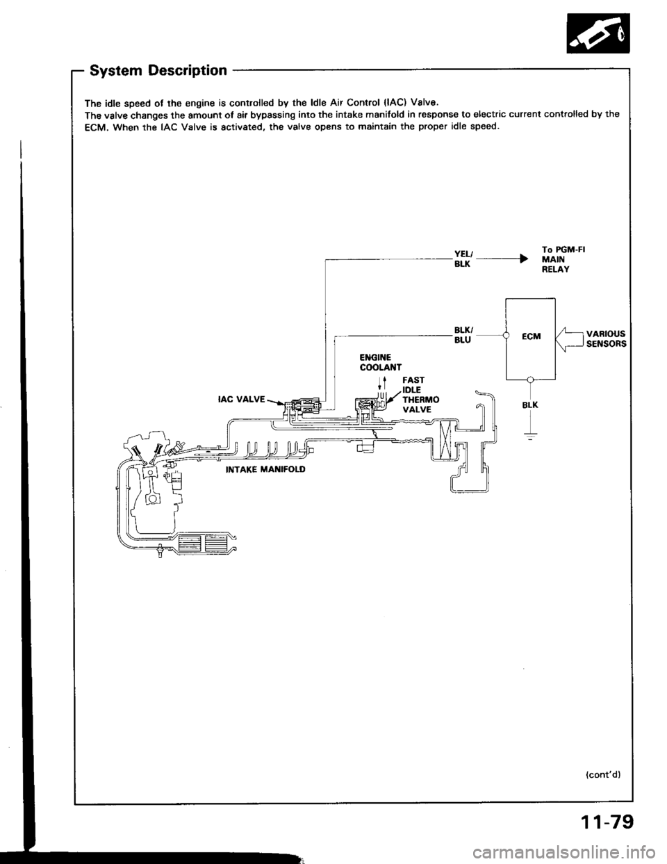
System Description
The idle speed ot lhe engine is controlled by the ldle Air Control {lAC) Valve.
The valve changes the amount ot air bypassing into the intake manifold in response to electric current controlled by the
ECM. When the IAC Valve is activated, the valve opens to maintain the proper idle speed.
#l' ----rTo FGM-FIMAINRELAY
VARIOUSSENSORS
IAC VALVE
FASTIDLETHERMOVALVE
INTAKE MAI{IFOLD
(cont'd)
BLK
r
11-79
Page 271 of 1413
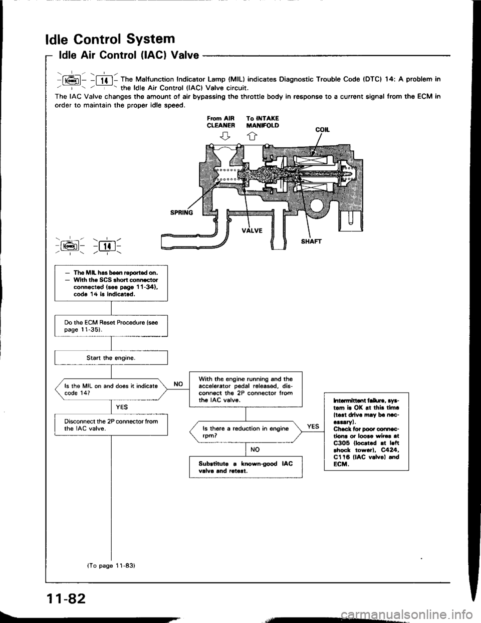
ldle Control System
ldle Air Control (lACl Valve
lt6l- -l lf l- The Maltunction Indicator Lamp (MlL) indicates Diagnostic Trouble Code {DTC} 14: A problem in
' '- the ldle Air Control llAC) Valve circuit.
The IAC Valve changes the amount of air bypasEing the throttle body in respons€ to a current signal from the ECM in
order to maintain the proper idle speed.
ffi: r;611/ | /--T-\
- The MIL h.3 been report don,- With tho SCS shon connoctolconnoctod (soo pago 'l 'l -341,
cod6 14 is indicatod.
Do the ECM Reset Procedure (seepage 11-35).
With the engine running snd theaccelerator pedal releas€d, dis-conn€ct th€ 2P connector frorttho IAC valvo.
ls the MIL on and does it indicatecode 14?
htarmitlaot frlu]., aya-t.m i. OK !t thir tlft.
ll.rl drlv. mly ba nac-aaaaryl.Chack tor Doo. conn€c-tlonr oi loora wirca atC3O5 (loc.t.d .t |.ftlhock tow.tl, C424,Cl tB (lAC v.lvol .ndECM.
Disconnect the 2P connector fromthe IAC valve.
Sub.iituto . known{ood IACvdva lnd iotolt.
{To page 11-83}
11-82
Page 395 of 1413
The Automatic Transmission is a combination of a 3-e,ement torque convefter and triple-shaft electfonically controlled
automatic transmission which provides 4 speeds forward and 1 speed reverse. The entire unit is positioned in line with
the engine.
Torque Converter, Gears and Clutches
The torque converter consists of a pump, turbine and stator assembly in a single unit, The torque converter is connected
to the engine crankshaft so they turn together as a unit as the engine turns. Around the outside of the torque converter
is a ring gear which meshes with the starter pinion when the engine is being staned. The entire torque converter assem-
bly serves as a flywheel while transmitting power to the transmission mainshaft.
The transmission has three parallel shafts, the mainshaft. countershaft and sub-shaft. The mainshatt is in line with the
engine crankshaft.
The mainshaft includes the clutches for 1 st, and 2ndl4th, and gears for 3rd. 2nd, 4th, reverse and l st (3rd gear is in-
tegral with the mainshaft, while reverse gear is integral with the 4th gear).
The countershaft includes the 3rd clutch and gears Ior 3rd, 2nd,4th, reverse, lst and parking. Reverse and 4th gears
can be locked to the countershaft at its center, providing 4th gear or reverse, depending on which way the selector is moved.
The sub-shaft includes the lst-hold clutch and gears for 1st and 4th
The gears on the mainshait are in constant mesh with those on the countershaft and sub-shaft. When certain combina-
tions of gears in the transmission are engaged by the clutches, power is transmitted from the mainshaft to the counter-
shaft via the sub-shatt to provide @, E, tr. tr and @ position.
Electronic Control
The electronic control system consists of the Transmission Control Module {TCM), sensors, and 4 solenoid valves. Shift-
ing and lock-up are electronically controlled for comfortable driving under all conditions.
The TCM is located below the dashboard, behind the left side kick panel on the driver's side.
Hydraulic Control
The valve bodies include the main valve body, secondary valve body, regulator valve body. servo body, and lock-up valve
body throuqh the respective separator plates.
They are bolted on the torque converter housing.
The main valve body contains the manual valve, 1-2 shift valve, 2-3 shift valve, Clutch Pressure Cont.ol (CPC) valve,
4th exhaust valve, relief valve, and oil pump gears.
The secondary valve body contains the 4-3 kick-down valve,3-2 kick-down valve,2-3 orifice cont.ol valve, 3-4 shitt
valve, orifice control valve. modulator valve, and servo control valve
The regulator valve body contains the pressure regulator valve. lock-up control valve, torque converter check valve, and
cooler check valve.
The servo bodv contains the servo valve which is integrated with the reverse shift fork, throttle valve B, and accumulators.
The lock-ug valve bodv contains the lock-up shift valve and lock-up timing B valve. and is bolted on the secondary valve
body.
Fluid from the regulator passes through the manual valve to the various control valves.
Shitt Control Mochanism
Input to the TCM i.om various sensors located throughout the car determines which shift control solenoid valve should
be activated.
Activating a shift control solenoid valve changes modulator pressure, causing a shift valve to move. This pressurizes
a line to one of the clutches. engaging that clutch and its corresponding gear.
Lock-up Mechanism
In @ position. in 2nd, 3rd and 4th, and E position in 3rd, pressurized tluid can be drained from the back of the tor-
que converter through an oil passage, causing the lock-up piston to be held against the torque converter cover. As this
takes Dlace, the mainshaft rotates at the same speed as the engine crankshatt. Together with hydraulic control, the TCM
optimizes the timing ol the lock-up mechanism.
The lock-up valves control the range of lock-up according to lock-up control solenoid valves A and B, and throttle valve B
When lock-up control solenoid valves A and B activate, modulator pressure changes. Lock-up control solenoid valves
A and B are mounted on the torque converter housing, and are controlled by the TCM.
(cont'd)
14-3
Page 413 of 1413
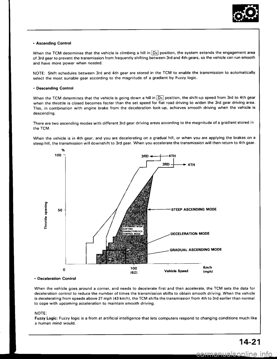
. Ascending Contlol
When the TCM determines that the vehicle is climbing a hill in @ position, the system extends the engagement area
of 3rd gear to prevent the transmission Irom frequenrly shitting between 3rd and 4th gears, so the vehicle can run smooth
and have more power when needed.
NOTE: Shift schedules between 3rd and 4th gear are stored in the TCM to enable the transmission to automatically
select the most suitable gear according to the magnitude of a gradient by Fuzzy logic.
. Descending Control
When the TCM determines that the vehicle is going down a hill in @ position. the shift-up speed from 3rd to 4th gear
when the throttle is closed becomes taster than the set speed for tlat road driving to widen the 3rd gear driving area.
This, in combination with engine brake from the deceleration lock-up, achieves smooth driving when the vehicle is
descending.
There are two ascending modes with different 3rd gear driving areas according to the magnitude of a gradient stored in
the TCM.
When the vehicle is in 4th gear, and you are decelerating on a gradual hill, or when you are applying the brakes on a
steep hill, the transmission will downshitt to 3rd gear. When you accelerate the transmission will then return to 4th gear.
F
0
. Deceleration Control
Vohicle SDood
When the vehicle goes around a corner, and needs to decelerate first and then accelerate, the TCM sets the data for
deceleration control to reduce the number of times the transmission shifts to obtain smooth driving. When the vehicle
is decelerating from speeds above 27 mph (43 km/h). the TCM shifts the transmission from 4th to 3rd earlier than normal
to cope with upcoming acceleration to maintain smooth driving.
NOTE:
Fuzzy Logic: Fuzzy logic is a from at artificial intelligence that lets computers respond to changing conditions much like
a human mind would.
14-21
Page 456 of 1413
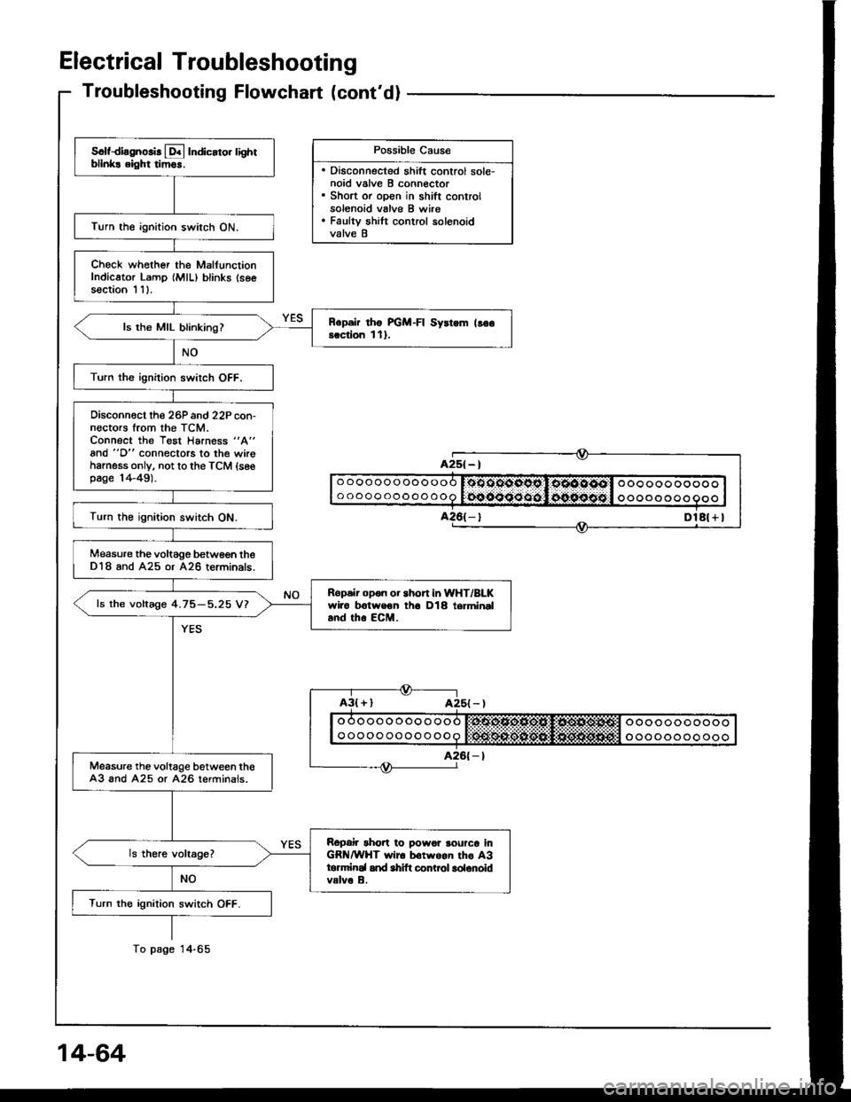
Electrical Troubleshooting
Troubleshooting Flowchart (cont'dl
Possible Cau6e
. Disconnected shift control sole-noid valve B connector. Short or open in shift controlsolenoid valve B wire. Faulty shilt control solenoidvalve B
Solfdiagnolir [!4 Indicato. lightbllnk! eight tim6r.
Turn the ignition switch ON.
Check whother the MalfunctionIndicator Lamp {MlL) blinks (seesection I 11.
Rcpsir rho FGM-FI Syrtem lso6scciion l1l.ls the MIL blinking?
Turn the ignition swirch OFF.
Oisconn€ct the 26P and 22P con-nectors trom the TCM.Connect the Test Harness "A"
and "D" connectors to the wirohamess only. not to the TCM {sesp6ge 14-49).
Turn the ignition switch ON.
Measure the voltage betwe€n theD18 and A25 or A26 terminals.
Ropeir opon or short in WHT/BLKwiro trotweon th6 D18 termineland tho EcM.
ls the voltage 4.75-5.25 V?
Measure the voltage between th€A3 and A25 or A26 terminals.
Ropair rhort to powor rourco inGR /WHT wir6 b€twgan tho A3tormirEl and shift conLol lolonoidvalve B.
Turn the ignition switch OFF.
A2s( - |
DlA( + I
o oooooooooo
ooooooooooooo oo ooo ooooo
oooo o o oo
To page