headlight circuit HONDA INTEGRA 1994 4.G Workshop Manual
[x] Cancel search | Manufacturer: HONDA, Model Year: 1994, Model line: INTEGRA, Model: HONDA INTEGRA 1994 4.GPages: 1413, PDF Size: 37.94 MB
Page 260 of 1413
![HONDA INTEGRA 1994 4.G Workshop Manual PGM-FI System
Electrical Load Detector (ELDI
tft;-]/ The Maltunction Indicaror Lamp (MlL) indicatss Diagnostic Trouble Code IDTC) 20: A probtem in-Li!- tne Electrical Load Detecror {ELD} circuit.
With HONDA INTEGRA 1994 4.G Workshop Manual PGM-FI System
Electrical Load Detector (ELDI
tft;-]/ The Maltunction Indicaror Lamp (MlL) indicatss Diagnostic Trouble Code IDTC) 20: A probtem in-Li!- tne Electrical Load Detecror {ELD} circuit.
With](/img/13/6067/w960_6067-259.png)
PGM-FI System
Electrical Load Detector (ELDI
tft;-]/ The Maltunction Indicaror Lamp (MlL) indicatss Diagnostic Trouble Code IDTC) 20: A probtem in-Li!- tne Electrical Load Detecror {ELD} circuit.
With lho SCS lhon connectolconnoctod {ree pago 11-34}, cod.20 is indicatod.
Do the ECM B6set Procedurs {seepage 1 'l-35).
Start engine and keep engin€speed at idle.Turn on headlights.
lntennlna tlllure, lyrtom lt Ol(!t irl. dm. (lgtt driv. mly [email protected] for Door connactlona oaloota wiro. rt C218 IELD, lndEctrt.
Ooes the MIL indicato code 20?
Romove the undgr-hood fusg/relay box and remove the tus6/relav box lowet cover.
Turn lhe ignition switch ON.
Measure voltage betw€on BLK/YEL (+l terminal and BLK (-)terminal.
Msasuro voltag€ b€tweon BLK/Y€L {+) terminal snd bodvground.ls there bartory voltagel
Rcpir oo.n in BLK wir.batwaan lha 3P connrc-tor lnd G2Ol {loc.t.dtroit ot angh|. comprn-m.r dghl .ld.l,
B.p.lr op.n in BLKrYEL wlrr b.-tw..n o.24ACG (ALn flcl115A: Bl88l .ngln!, 20 A:818C1cnginol fu!. In thr und.r{..htu.o/r.lly bor lnd tho 3P con-rcclo?.
View tromwire side
BLK (-)
(To page 11-7'l)
GRn/iED I - |
BLK/YEL I + I
11-70
Page 1107 of 1413

Electrical
Special Tools
Troubleshooting
Tips and Precautions ................................ 23-3Five-stop Tloubleshooting ..............,...-..-... Z3-sSchematic Symbols ................................_. 23-6wire Color Cod€s ..................................... 23-6Relay and Control Unit Locations
Engine Compartment .........,............ ... --. 23-7Dsshboard and Door ..,,......................... 23-gDashboard and Floor ............................. 23-t OOuaner Panel .....-.....23-12Connector ldentification and WireHarness Routing ........ 23-i 3
Index to Circuits and Systems
Airbag ............... ...-..-... 2g-26sAir Conditioning ....,.. Section 2lAltelnator ......_.............. 23-99Anti-lock Brake Systsm (ABS) Section 19Automatic Transmission Section 14Battery .............. .......... 23-66Chafging System ........... 23-98rCigalstte Lighter .....................-...-......-..-.. Z3-2O4Cfock ................. ..........23-197rcruise Controf .......--..-... 23-242Distributor .................... 23-87Fan Controls ................. 23-1ogFuel and Emissions ... Section 1i*Fuses
Under-dash Fuse/Relay Box ................... 23-48Undor-hood ABS Fuse/Retay Box ............ 23-51Under-hood Fuse/Relay Box,.................. 23-52rGauges
Engine Coolant Temperature {ECT)Gauge ................ ..23-126Fuef cauge ............... 2g-123'Gauge Assembly ....--.23-113Speedometer .....-...,,. 23-114Tachometer .....,.....-.. 23-114Ground Distribution ........ 23-60Heater ,,,........,.... ..... Section 2lrHorn ................. ........... 23-199*fgnition Switch ............. 23-70fgnition Syst6m .......-..-.. 23-A7lgnition Timing .............. 23-89Indicator Lights"A/T Gear Position .............. ................... 23-1 32B1ak6 System ...,..,..-.23-127Engine Oil Pressura .............................. _ 23-1 51Low Fuel ............ ......23-125Malfunction Indicator Lamp {MlL} ...,,. Section I l
tfnteglated Control Unit ...29-144*lnterlock System ...................................... 23-1 3gLights, Exteriol
Back-up Lights ........... 23-179Brake Lights .............. 23-t8ltDaytime Running Lights {Csnada} ........... 23-156Front Palking Lights ............................. 23-1 65Flont Side Marker Lights ....................... 23-165Front Turn Signal Lights ........................ 23-1 65*Hazard Warning Lights .........................- 2g-1A4Headlights ................. 23-t6tLicense Plate Lights .............................. 23-1 69Taillights(Harchback) .......... 23-166
{Sedan) .............. .. 23-167Lights. Inteliol
Cargo Area Light {Hatchback) ...... -.. -.. -... 23-177Ceifing Light ........-..-.23-175
Dash Lights Blightness Controt .............. 23-t70Glove Box Lighr ................................... 23-1 69Spotfighr ............ ....-.23-174Trunk Light (Sedanl ............... .............. - 23.-177*Lighting Sysrem .......-.-... 23-152:Moonroof ,,.,.......,..,,,,,.-.23-211PGM-FI Systom ........ S€crion 11Power Distribution .,.-..--..23-54Power Door Locks .............,,..................... 23-233Power Mirors ..,..,....-...- 23-216Power Relays ...........,..... 23-68Power Windows ............ 29-222*Rear Window Defogger ........,... ..........,..... - 23-20,6Reminder Systems
Key-in Remindel System ....,.............,.... 23-1 50Lights-on Reminder System ................... 23-l 5f*Maintenance Reminder system ..,,.... -.. - -. 23-.1 2gSeat Belt Reminder System ..................- 23-125*Side Markel/Turn Signal/Hazard
Ffasher System .,..,..-.23.-1A4Spark Pfugs .........-...-..... 23-97Starting System ....,,.....-. 23-73*Stereo Sound System ...,.......................,,.. 23-l gg
Supplemental Restraint System {SRS} ......... 23-265Vehicfe Speed Sensor {VSS) .............--..-.... 23-122*Wiper/Washer Systom ...............--.........-..- Zg-254
rRead SRS pi€cautions on Page 23-271 betore workingin these areas.
-+
Page 1155 of 1413

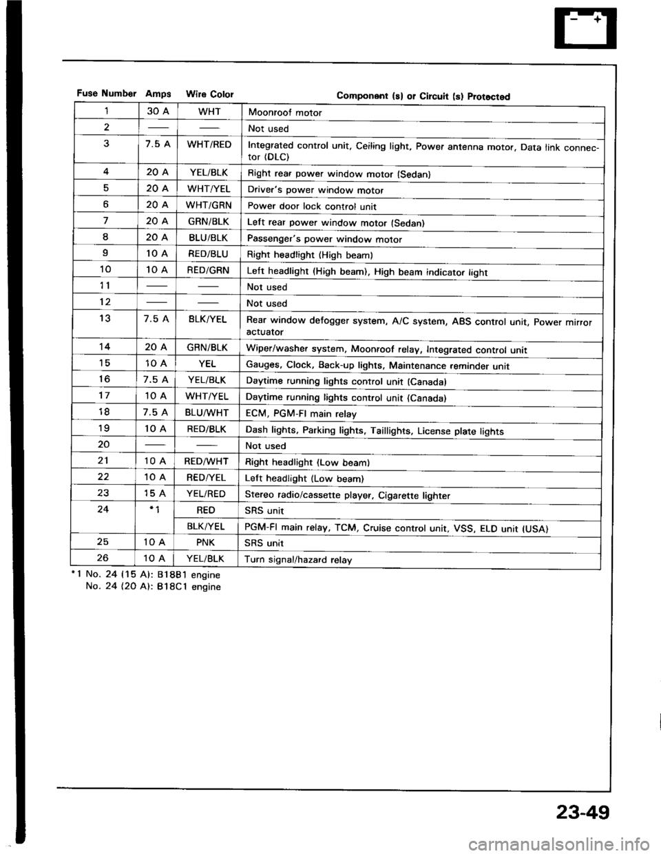
Fuse Numb€r AmDs Wire CololGomponent ls) or Circuit (s) Prot8cted
130AWHTMoonroof motor
2Not used
37.5 AWHT/REDIntegrated control unit, Ceiling light, Power antenna motor. Data link connec-tor (DLC)
420AYEL/BLKRight rea. power window motor (Sedan)
520AWHT/YELDriver's power window motor
o20AWHT/GRNPower door lock control unit
720AGRNiBLKLelt rear power window motor (Sedan)
I20ABLU/BLKPassenger's power window motor
I10 ARED/BLURight headlight {High beaml
1010 ARED/GRNLeft headlight (High beam). High beam indicato. tight
11Not used
12Not used
137.5 ABLK/YELRear window defogger system, A/C system, ABS control unit, power mrrroractuator
1420AGRN/BLKWiper/washer system, Moonroof relay, Integrated control unii'1510 AYELGauges, Clock, Back-up lights, Maintenance reminder unit
to7.5 AYEL/BLKDaytime running lights control unit (Canadal
1710 AWHT/YELDaytime running lights control unit (Csnada)
7.5 ABLU^tvHTECM, PGM-FI main relay'to10 ARED/BLKDash lights, Parking lights, Taillights, License plate tights
20Not used
2110 ARED/WHTRight headlight (Low beam)
10 ARED/YELLeft headlight (Low beam)
2315 AYEL/REDStereo radio/cassette player, Cigarette lighter
24REOSRS unit
BLK/YELPGM-FI main relay, TCM, Cruise controt unit, VSS, ELO unit IUSA)
2510 APNKSRS unit
2610 AYEL/BLKTurn signal/hazard relay'1 No.
No.
24 115 Al:
24 t2O At:.
81881 engine
B18Cl engine
23-49
Page 1260 of 1413
![HONDA INTEGRA 1994 4.G Workshop Manual Lighting System
Circuit Diagram (USAI
UNOER - HOOD RJSE/NELAY 8OX
-r lo| ,-. otFDIMMER II
No.2l|l0A]iil;
)
ttNo.lo 1 No,22 t No.gtloAr (0oA) (floAr
IT
HEADLIGHTRIGHTHEAOUGHT
HIGH EEAMINOICATORLIGH HONDA INTEGRA 1994 4.G Workshop Manual Lighting System
Circuit Diagram (USAI
UNOER - HOOD RJSE/NELAY 8OX
-r lo| ,-. otFDIMMER II
No.2l|l0A]iil;
)
ttNo.lo 1 No,22 t No.gtloAr (0oA) (floAr
IT
HEADLIGHTRIGHTHEAOUGHT
HIGH EEAMINOICATORLIGH](/img/13/6067/w960_6067-1259.png)
Lighting System
Circuit Diagram (USAI
UNOER - HOOD RJSE/NELAY 8OX
-r lo| ,-. otFDIMMER I'I
No.2l|l0A]iil;
)
ttNo.lo '1 No,22 ''t No.gtloAr (0oA) (floAr
IT
HEADLIGHTRIGHTHEAOUGHT
HIGH EEAMINOICATORLIGHTfi.4W)@il,", @f,*,6il* 6p*
. PAR(II{G UGHI. TAILUGI{TS. UCENSE PI.ATE
UtrloER - D SHRJSE/RELAYsox
REO/GNN
8LK
I
G20lG401
DASH UGI{TS88rGr{T ESSCONTrcUTRDASH UGHTSPAR(II{C UGHTSTAItUGt{TSUCENSE PI.ATEUGHTS
8tK
G301G20'�|G40l
23-154