icm HONDA INTEGRA 1994 4.G Workshop Manual
[x] Cancel search | Manufacturer: HONDA, Model Year: 1994, Model line: INTEGRA, Model: HONDA INTEGRA 1994 4.GPages: 1413, PDF Size: 37.94 MB
Page 196 of 1413
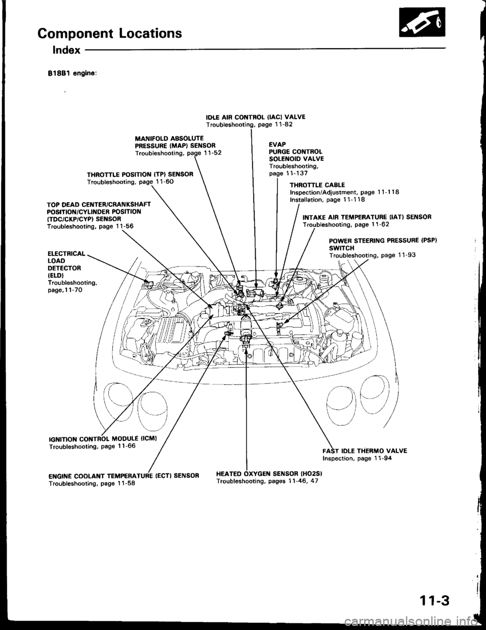
Component Locations
lndex
81881 sngin6:
IOLE AIR CONTROL OACI VALVEpage '11-82T
MANIFOLD ABSOLUTEPRESSURE {MAP} SENSOREVAP
THROTTLE POSITIOIII {TP) SENSORTroubleshooting, page 1 1-60
Troubleshooting,
(ECTI SENSOR HEATEO
PURGE CONTROLSOLENOID VALVETroubleshooting,11-137
THROTTLE CABLEInspection/Adiustment, page 1 1-1 18
Installation, page 11- 1 18
SENSOR lHO2S}
TOP DEAD CENTER/CRATIIKSHAFTPOSITIOf{/CYLINDER POSITION(TDC/CKP/CYP} SENSORTroubleshooting, page 1 1-56
INTAKE AIR TEMP€RATURE IIAT) SEI{SORTroubl€shooting, page 1 1 -62
POWER STEERING PRESSURE (PSP)
swtTcHTroubleshooting. page 11-93
sq
IDLE THERMO VALVEInspection, page 11-94
ELECTRICALLOADOETECTORIELD}Troubleshooting.page,l l-70
IGNITIONMODULE {ICMI
Troubleshooting, page 1 1-66
ENGINE COOLANT TEMPERATroubleshooting, page I 1-58Troubleshooting. pages 11-46, 47
11-3
Page 257 of 1413
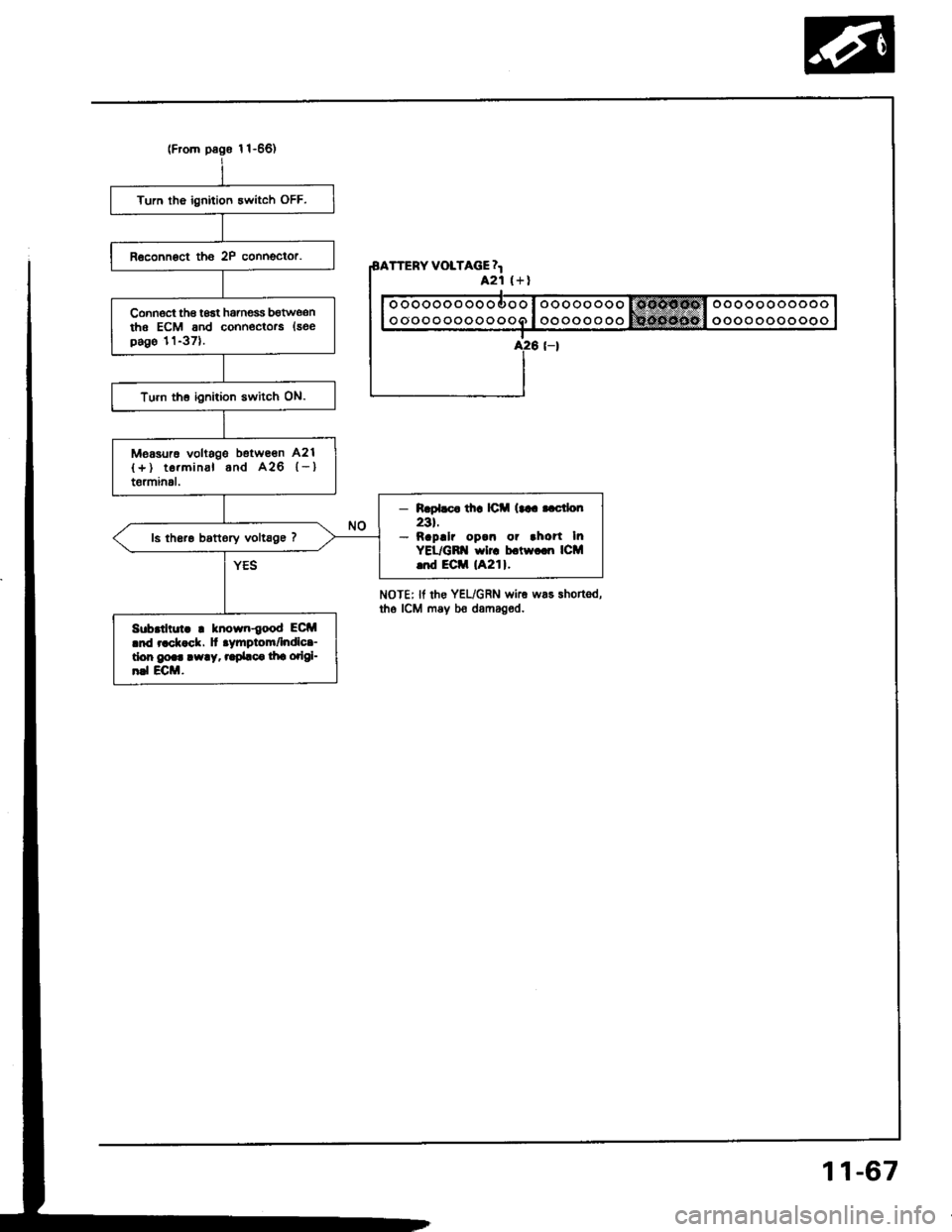
Turn tho ignition 3witch OFF.
Connoct th€ toat hamess bgtwe,snthe ECM and conn€ctors {seepago 11-371.
Turn th6 ignition switch ON.
Measurc voltags betwe€n A21
{+) te.minal and A26 {-}t6rminal.
- R.pl.c. th! lC (trr..ctlo[
23t.- napllr op.n or .ho?t InYEL/GB'{ wlrc b.tw.cn ICM..d Eciil lA21l.
ls th6re bottory vollsge 7
Sub.thut. ! known{ood ECM.nd r.ck ck. ]t .ymptom/lndlc.-don go.. !w!y, ..pbc. lha odgl-n.l ECM.
TTERY VOLTAGE 4421 (+l
ooooooooooooo
oooooooooooo
NoTEr lf rhe YEL/GRN wke was shortsd,tho ICM may bo damaged.
11-67
Page 1162 of 1413
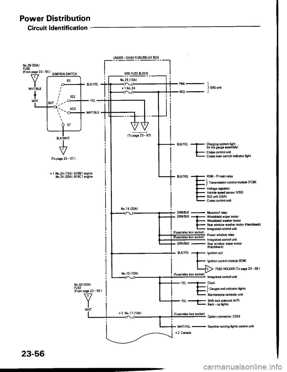
Power Distribution
Circuit ldentification
IGNITION SWITCH
+page 23-
r 1 No.24115A): 81881 engin€No.24 l20A): Bl8C1 6ngin.
N0.40 {504)FUSE(From pago 23 - 551
UNDER - DASH FUSE/REIAY BOX
sRs FusE 81-0cK
No.25l10Al
No.14l20A)
No.l5 {1041
Chuging sY3l.m lightlln tho g6ug€ s3€mblyl
Cruis€ controlunitCdis6 msin 3whch itdicttor light
PGM - Fl mlin r6lry
) lrrmmirdon control modulo [ICM)
Vohag6 rcoulatorVehiclo sp.€d somor IVSS)E|.l) unit IUSA)Crube conttol unit
Moonrcof rclayWind.hicld wipot motorWirdlhi€ld waah6. motorR6ar window ws3hor motot {HrtchblctlInt.gGtod control unit
Power wirdow tclaY
Int6lrat€d contrcl unit- R6af window wipor motol(H3tchbtck)
571
GRNiEI(GRNAt(
GRN/8I..K
BLKffEt
-EiT"h#,H#J:r"
Shitt lock solenoU {MlEack -up lights
option conn€ctor: C924
Daytimo running lights conttol unit
YEt..--
lrcz
Ml t -'-
\'- _ ^ACC
23-56
*2 No.17 {1041bor sockstl
Page 1199 of 1413
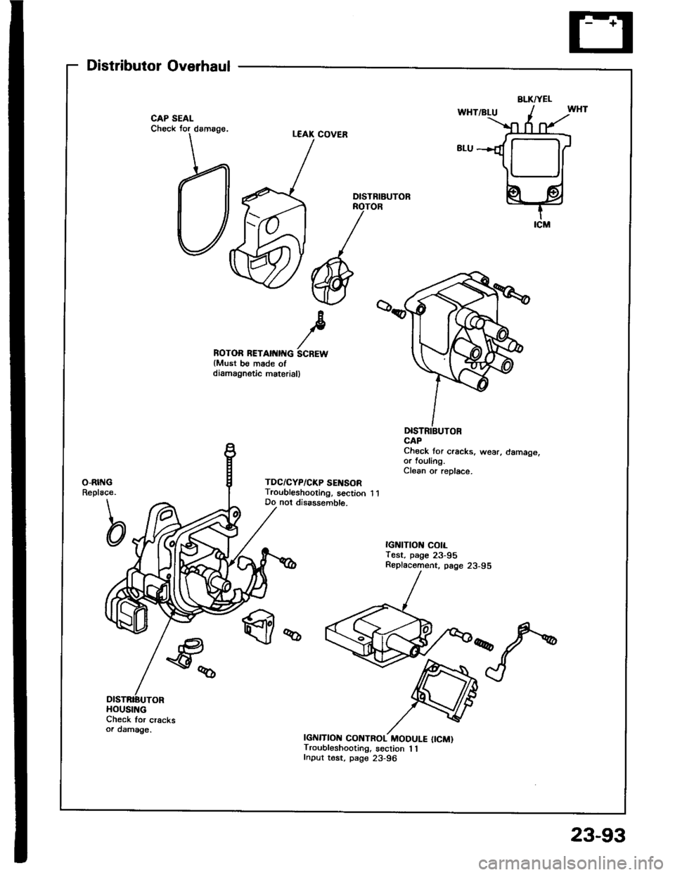
Distributor Overhaul
Check for cracksoa damage.
ROTOR RETAII{IITG SCREWlMust be made ofdiamagnstic materiall
DlsTNIBUTOR
Chock tor cracks, wear, damage,or fouling.Clean or replace.
IGNITION CONTROL MODULE {ICM)Troubleshooting, section 1 1Input tost, page 23-96
BLKTYEL
HOUSING
23-93
Page 1202 of 1413
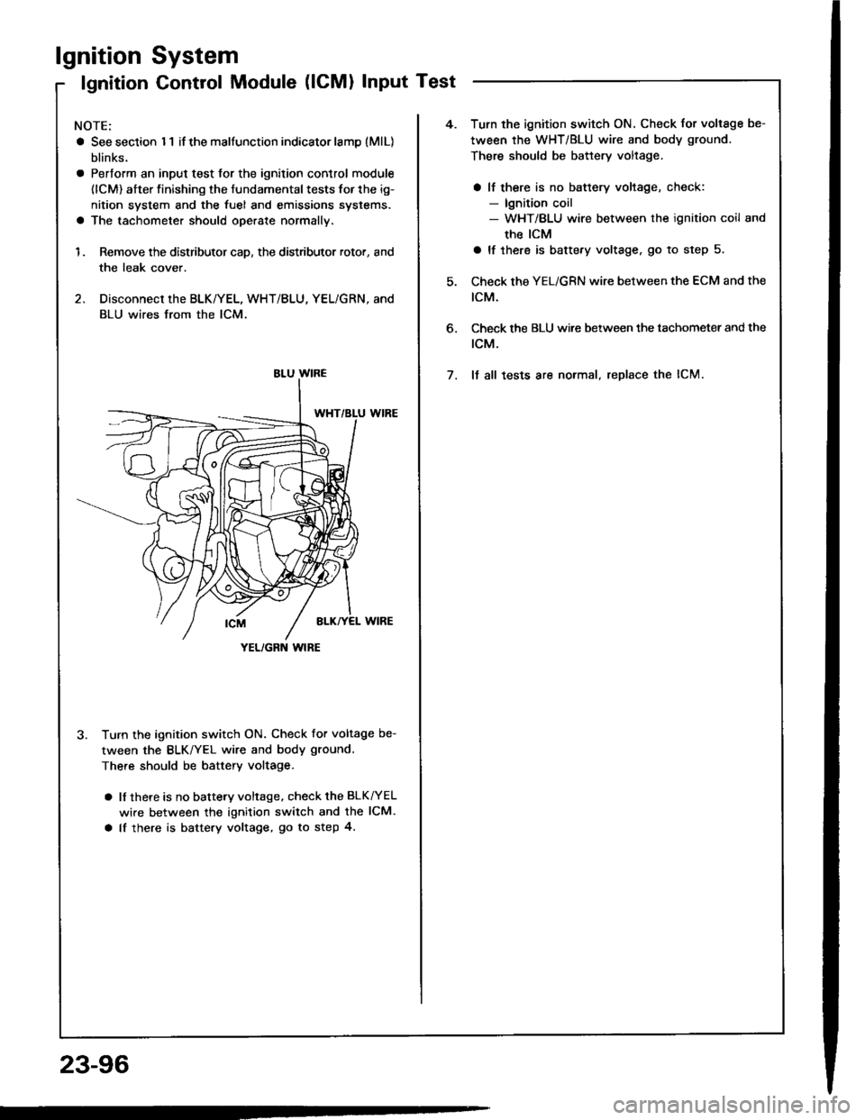
lgnition
lgnition
System
Control Module (lCMl Input Test
NOTE:
a See section I 1 if the malfunction indicator lamD (MlL)
blinks.
a Pertorm an input test for the ignition control module
(lCM) after finishing the fundamental tests for the ig-
nition system and the fuel and emissions systems.
a The tachometer should operate normally.
1. Remove the distributor cap, the distributor rotor, and
the leak cover.
2. Disconnect the BLK/YEL, WHT/BLU, YEL/GRN, and
BLU wires from the lCM.
3. Turn the ignition switch ON. Check for voltage be-
tween the BLK/YEL wire and body ground.
There should be battery voltage.
a lf there is no battery voltage, check the BLK^/EL
wire between the ignition switch and the lCM.
a lf there is battery voltage, go to step 4.
YEL/GRN wlRE
4.Turn the ignition switch ON. Check for voltage be-
tween the WHT/BLU wire and body ground.
There should be battery voltage.
a lf there is no battery voltage, check:- lgnition coil- WHT/BLU wire between the ignition coil and
the ICM
a lf there is battery voltage. go to step 5.
Check the YEL/GRN wire between the ECM and the
tcM.
Check the BLU wi.e between the tachometer and the
rcM.
It all tests are normal, replace the lCM.
6.
7.
23-96