main relay HONDA INTEGRA 1998 4.G Owners Manual
[x] Cancel search | Manufacturer: HONDA, Model Year: 1998, Model line: INTEGRA, Model: HONDA INTEGRA 1998 4.GPages: 1681, PDF Size: 54.22 MB
Page 1629 of 1681
Connectol
ol
Terminal
Number ot
Cavities/
Color
LocationConnects toNotes
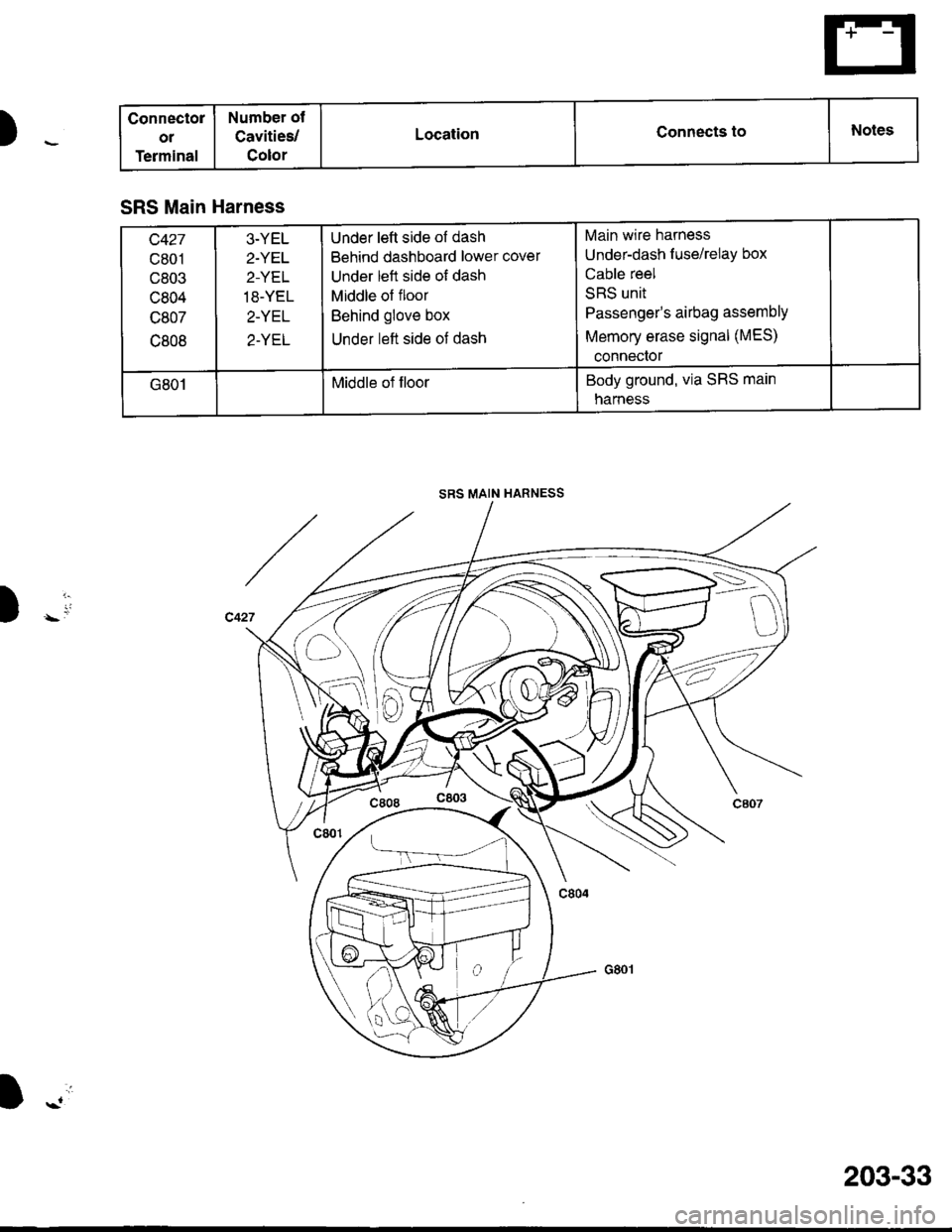
SRS Main Harness
c427
c801
c803
c804
c807
c808
3-YEL
2.YET
2-YEL
18-YEL
2-YEL
2-YEL
Under left side of dash
Behind dashboard lower cover
Under left side of dash
Middle of floor
Behind glove box
Under left side of dash
Main wire harness
Under-dash f use/relay box
Cable reel
SRS unit
Passenger's airbag assemblY
Memory erase signal (MES)
conneclor
G801Middle of floorBody ground, via SRS main
narness
SRS MAIN HARNESS
Y1-
D)
I -.'i
203-33
Page 1632 of 1681
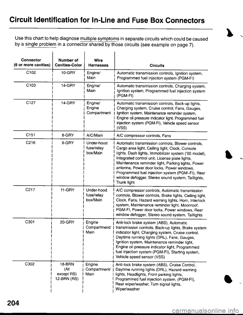
Circuit ldentification for In-Line and Fuse Box Connectors
Use this chart to help diagnose multiple symptoms in separate circuits which could be caused
by a single problem in a connector shared by those circuits (see example on page 7).
Connector
(6 or more cavities)
Number of
Cavities-Color
Wire
Harnesses
Engine/
Main
Engine/
Engine
Compartment
I Automatic transmission controls, lgnition system,
i Programmed fuel injection system (PGM-F|)
Automatic transmission controls, Charging system,
lgnition system, Programmed fuel injection system(PGM-FI)
Automatic transmission controls, Back-up lights,
Charging system, Cruise control, Fans, Gauges,
lgnition system, Maintenance reminder system,
Engine oil pressure indicator light, Programmed fuel
injection system (PGM-Fl), Vehicle speed sensor
ffss)
| {c/Main! A,/C compressor controls, Fans
Under-hood
fuse/relay
box/Main
Automatic transmission controls, Blower controls,
Cargo area light, Ceiling light, Clock, Console
lights, Dash lights, lmmobilizer system ('00 model),
Integrated control unit, License plate lights,
Maintenance reminder light, Parking lights, Power
antenna, Power door locks, Power windows,
Programmed fuel iniection system (PGM-Fl), Rear
window defogger, Stereo sound system, Taillights,
Trunk lioht
11-GRY
18-BBN
(4il
except BS)
12-BBN (RS)
Under-hood
fuse/relay
box/Main
Engine
CompartmenV
Main
Engine
CompartmenU
Main
lr,/C compressor controls, Automatic transmission
controls, Blower controls, Brake lights, Ceiling light,
Clock, Fans, Hazard warning lights, Horn, Interlock
system, Maintenance reminder light, Moonroof ,PGM-FI, Power door locks, Power windows, Rear
window defogger, Stereo sound system, Taillights
Anti-lock brake system (ABS), Automatic
transmission controls, Back-up lights, Brake system
indicator light, Charging system, Cruise control,
Daytime running lights (DRL), Fans, Gauges,
lgnition system, Maintenance reminder light,
Engine oil pressure indicator light, Programmed
tuel injection system (PGM-F|), Starting system,
Vehicle speed sensor (VSS)
Anti-lock brake system (ABS), Cruise Conkol,
Daytime running lights (DRL), Hazard warning
lights, Headlights, Front parking lights,
Programmed fuel injection system, (PGM-Fl),
Rear wiper/washer, Turn signal lights,
Wiper/washer
204
Page 1633 of 1681
)ot
Connector
(6 or more cavities)
Number of
Cavities-Color
25-GRY
1O-GRY
Wire
Harnesses
Front
passenger's
door/Main
Heater sub-
harness A,/
Main
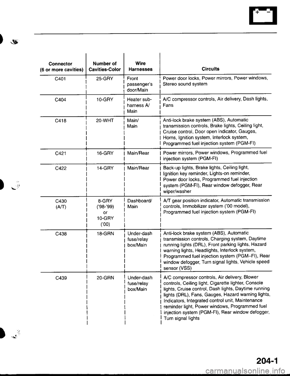
Circuits
Power door locks, Power mirrors, Power windows,
Stereo sound svstem
fuC compressor controls, Air delivery, Dash lights,
Fans
transmission controls, Brake lights, Ceiling light,
Cruise control, Door open indicator, Gauges,
Horns, lgnition system, Interlock system,
Programmed fuel injection system (PGM-Fl)
Main/
Main
Anti-lock brake system (ABS), Automatic
16.GRYMain/RearPower mirrors, Power windows, Programmed tuel
injection system (PGM-Fl)
14-GRYMain/RearBack-up lights, Brake lights, Ceiling light,
lgnition key reminder, Lights-on reminder,
Power door locks, Programmed fuel iniection
system (PGM-Fl), Rear window defogger, Rear
wiDer/washer) -io
tl
c430
(An)
8-GRY
(e8-'ee)
or
1O-GRY
(00)
18-GRN
Dashboard/
Main
Under-dash
fuse/relay
box/Main
A/T gear position indicator, Automatic transmission
controls, lmmobilizer system ('00 model),
Programmed fuel injection system (PGM-Fl)
Anti-lock brake system (ABS), Automatic
transmission controls, Charging system, Daytime
running lights (DBL), Front parking lights, Hazard
warning lights, Headlights, lnterlock system,
Programmed fuel injection system (PGM-Fl), Rear
window defogger, Turn signal lights, Vehicle speed
c43920-GRNUnder-dash
fuse/relay
box/Main
sensor (VSS
L/C compressor controls, Air delivery, Blower
controls, Ceiling light, Cigarette lighter, Console
lights, Cruise control, Dash lights, Daytime running
lights (DRL), Fans, Gauges, Hazard warning lights,
Indicators, lntegrated control unit, Maintenance
reminder light, Power windows, Programmed fuel
injection system (PGM-Fl), Rear window defogger,
Turn signal lights
)
204-1
Page 1634 of 1681
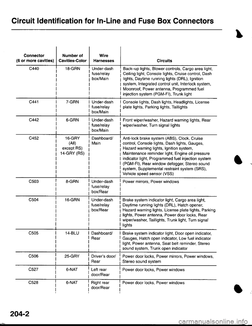
Circuit ldentification for In-Line and Fuse Box Gonnectors
Connector
(6 or more cavities)
Number of
Cavities-Color
18.GRN
Wire
Harnesses
Under-dash
fuse/relay
borMain
Circuits
Back-up lights, Blower controls, Cargo area light,
Ceiling light, Console lights, Cruise control, Dash
lights, Daytime running lights (DRL), lgnition
system, Integrated control unit, Interlock system,
Moonroof, Power antenna, Programmed fuel
injection system (PGM-Fl), Trunk light
7-GRNUnder-dash
fuse/relay
box/Main
Console lights, Dash lights, Headlights, License
plate lights, Parking lights, Taillights
c4426-GRN
16-GRY
(Ail)
except RS)
14-GRY (RS)
16-GRN
Under-dash
tuse/relay
box/Main
Dashboard/
Main
Under-dash
fuse/relay
box/Rear
Under-dash
fuse/relay
box/Rear
Front wiper/washer, Hazard warning lights, Rear
wiper/washer, Turn signal lights
Anti-lock brake system (ABS), Clock, Cruise
control, Console lights, Dash lights, Gauges,
Hazard warning lights, lgnition system,
Maintenance reminder light, Engine oil pressure
indicator light, Programmed fuel injection system
(PGM-Fl), Rear window defogger, Stereo sound
system, Supplemental restraint system (SRS),
Vehicle speed sensor (VSS)
Power mirrors, Power windows
Brake system indicator light, Cargo area light,
Daytime running lights (DRL), Hatch opener,
Hazard warning lights, License plate lights, Parking
lights, Power antenna, Power door locks, Rear
wiper/washer, Taillights, Trunk light, Turn signal
liohts
Dashboard/
Rear
Brake system indicator light, Door open indicator,
Gauges, Hatch open indicator, Low fuel indicator
light, Power antenna, Seat bell reminder, Stereo
sound system, Trunk open indicator
25-GRYDriver's door/
Rear
Left rear
door/Rear
Power door locks, Power mirrors, Power windows,
Stereo sound svstem
I Power door locks, Power windows
lJczat6-NATRight rear
door/Rear
I Power door locks, Power windowsI
a
204-2
Page 1635 of 1681
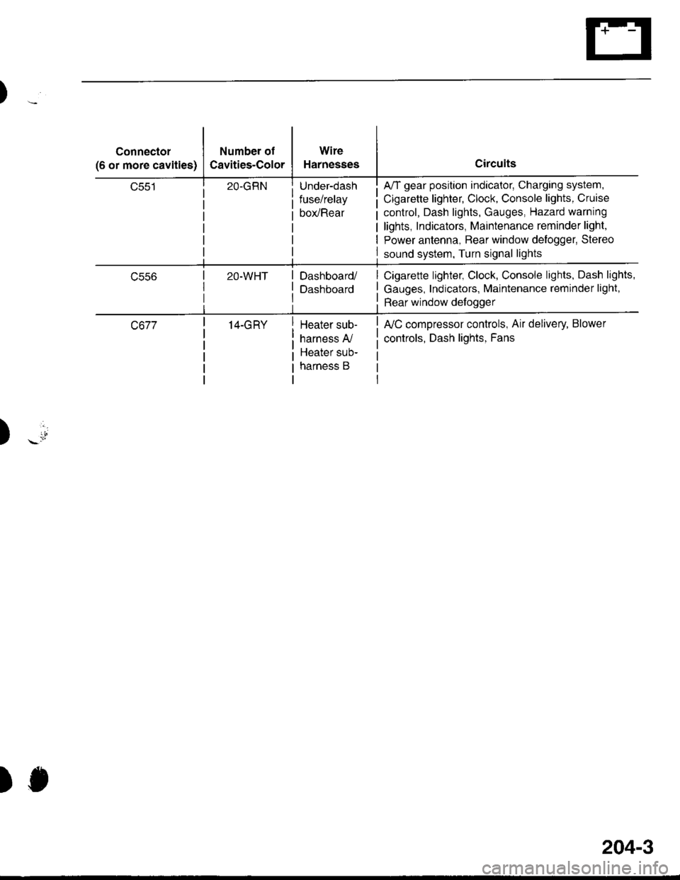
Connector
(6 or more cavities)
Number of
Cavities-Color
Wire
Harnesses
Under-dash
fuse/relay
box/Rear
A/T gear position indicator, Charging system,
Cigarette lighter, Clock, Console lights, Cruise
control, Dash lights, Gauges, Hazard warning
lights, Indicators, Maintenance reminder light,
Power antenna, Bear window delogger, Stereo
sound system, Turn signal lights
ucco2O-WHTDashboard/
Dashboard
Cigarette lighter, Clock, Console lights, Dash lights,
Gauges, Indicators, Maintenance reminder light,
Rear window defoggerrtl
c67714-GRYHeater sub-
harness A,/
Heater sub-
harness B
fuC compressor controls, Air delivery, Blower
controls, Dash lights, Fans
)
)J
204-3