coolant temperature HONDA INTEGRA 1998 4.G User Guide
[x] Cancel search | Manufacturer: HONDA, Model Year: 1998, Model line: INTEGRA, Model: HONDA INTEGRA 1998 4.GPages: 1681, PDF Size: 54.22 MB
Page 247 of 1681
1l
Troubleshooting
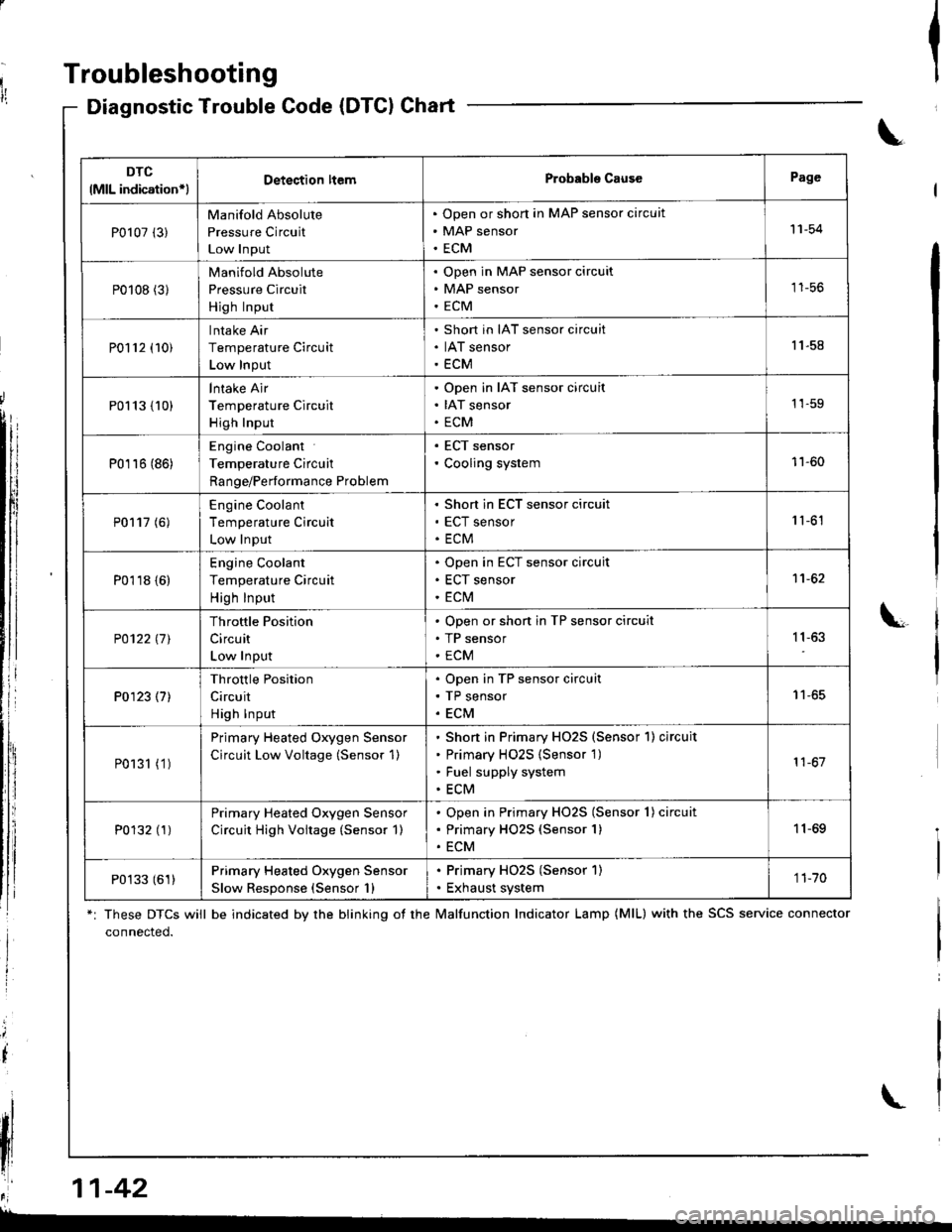
Diagnostic Trouble Gode (DTCI Chart
*: These DTCS will be indicated by the blinking ot the lvalfunction Indicator Lamp (MlL) with the SCS service connector
connected.
Ia
\
\
il
\
DTC
lMlL indication*lDetection ltemProbabls CausePage
P0107 (3)
Manifold Absolute
Pressure Circuit
Low Input
Open or short in MAP sensor circuit
MAP sensor
ECM
'11-54
P0108 (31
Manifold Absolute
Pressure Circuit
High Input
Open in MAP sensor circuit
MAP sensor
ECM
tt-5t,
P0112 (10)
Intake Air
Temperature Circuit
Low Input
Short in IAT sensor circuit
IAT sensor
ECM
11.58
P0113 {10)
lntake Air
Temperature Circuit
High Input
Open in IAT sensor circuit
IAT sensor
ECM
1'�1-59
P0116 (86)
Engine Coolant
Temperature Circuit
Range/Performance Problem
. ECT sensor' Cooling system11-60
P0117 (6)
Engine Coolant
Temperature Circuit
Low Input
Short in ECT sensor circuit
ECT sensor
ECM
1 '�t-61
P0118 {6)
Engine Coolant
Temperature Circuit
High Input
Open in ECT sensor circuit
ECT sensor
ECt\,4
1't -62
P0122l7l
Throttle Position
Circuit
Low Input
Open or shon in TP sensor circuit
TP sensor
ECM
11,63
P0123 (7)
Throttle Position
Circuit
High Input
Open in TP sensor circuit
TP sensor
ECM
I t-oc
P0131 (1 )
Primary Heated Oxygen Sensor
Circuit Low Voltage (Sensor 1)
Shon in Primary HO2S (Sensor'l) circuit
Primary H02S {Sensor 1)
Fuel supply system
ECM
11-67
P0132 (1)Primary Heated Oxygen Sensor
Circuit High Voitage (Sensor 1)
Open in Primary HO2S (Sensor 1) circuit
Primary HO2S (Sensor 1)
ECM
11-69
P0133 (61)Primary Heated Oxygen Sensor
Slow Response (Sensor 1)
. Primary HO2S (Sensor 1). Exhaust system1 1-70
,r:' 11-42
L
Page 253 of 1681
PGM-FI System
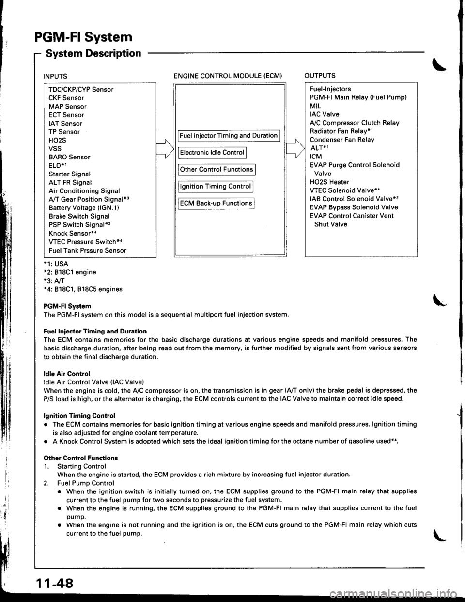
System Description
ENGINE CONTROL MODULE (ECM)OUTPUTS
*1: USA*2: 818C1 engine*3: A,/T*4: 818C1, 818C5 engines
PGM-FI Sy3tem
The PGM-Fl system on this model is a sequential multiport fuel injection system.
Fuel lniector Timing and Duration
The ECM contains memories for the basic discharge durations at various engine speeds and manifold pressures. The
basic discharge duration, after being read out from the memory. is further modified by signals sent from various sensors
to obtain the final discharge duration.
ldle Air Control
ldle Ai. Control Valve (lAC Valve)
When the engine is cold, the Ay'C compressor is on. the transmission is in gear (Ay'T only)the brake pedal is depressed, the
P/S load is high, or the alternator is charging, the ECM controls current to the IAC Valve to maintain correct idle speed.
lgnition Timing Control
. The ECM contains memories for basic ignition timing atvarious engine speeds and manifold pressures, lgnitiontiming
is also adjusted for engine coolant temperature.
. AKnockControl System isadoptedwhich sets the ideal ignition timing for the octane n um ber of gasoline used*r,
Other Control Functions
L Starting Control
When the engine is started, the ECM provides a rich mi{ure by increasing fuel injector duration.
2. Fuel PumD Control
. When the ignition switch is initially turned on, the ECM supplies ground to the PGM-FI main relay that supplies
current to the fuel pump for two seconds to pressurize the fuel system.
. When the engine is running, the ECM supplies ground to the PGM-FI main relay that supplies current to the fuel
DUmO.
. When the engine is not running and the ignition is on. the ECM cuts ground to the PGM-FI main relay which cuts
current to the fuel oumo.
INPUTS
TDc/CKP/CYP Sensor
CKF Sensor
MAP Sensor
ECT Sensor
IAT Sensor
TP Sensor
HO2S
VSS
BARO Sensor
ELD*1
Starter Signal
ALT FR Signal
Air Conditioning Signal
A,/T Gear Position Signal*3
Battery Voltage (lGN.1)
Brake Switch Signal
PSP Switch Signal*'�
Knock Sensor*1
VTEC Pressure Switch*4
Fuel Tank Prssure Sensor
Fuel InjectorTiming and Duration
Electronic ldle Control
Other Control Functions
lgnition Timing Control
ECM Back-uD Functions
Fuel-lnjectors
PGM-Fl Main Relay (Fuel Pump)
MIL
IAC Valve
A,/C Compressor Clutch Relay
Radiator Fan Belay*1
Condenser Fan Relay
ALT*1
rcM
EVAP Purge Control Solenoid
Valve
H02S Heater
VTEC Solenoid Valve*'
IAB Control Solenoid Valve*,
EVAP Bypass Solenoid Valve
EVAP Control Canister Vent
Shut Valve
11-48
Page 265 of 1681
PGM-FI System
Engine Coolant Temperature (ECTI Sensor
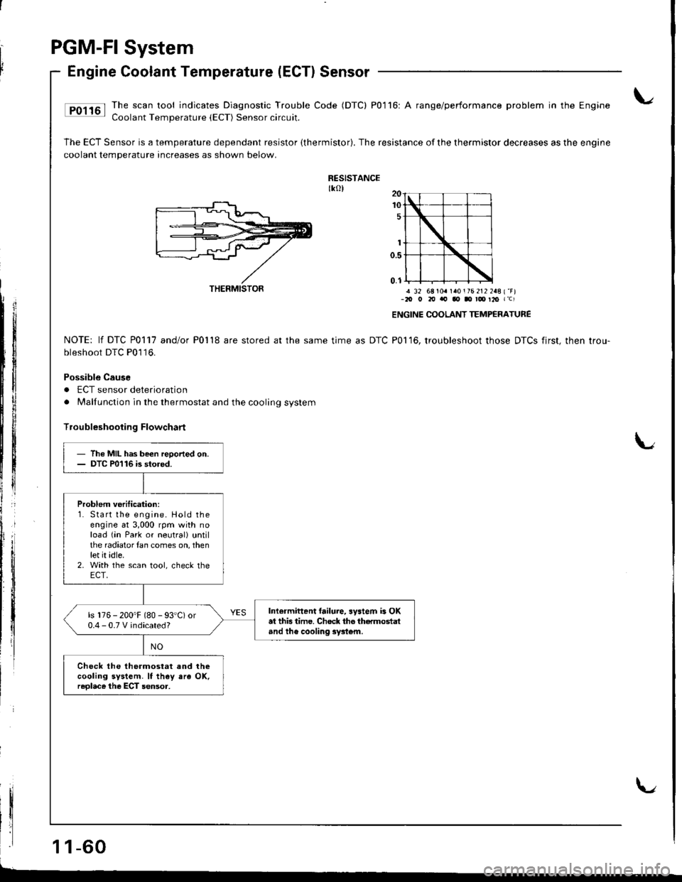
Ip01161 Ihe,scaltool indicates Diagnostic Trouble Code (DTC) P0116: A range/performance problem in the Engine: Coolant Temperature {ECT) Sensor circuit.
The ECT Sensor is a temperature dependant resistor (thermistor). The resistance of the thermistor decreases as the engine
coolant temperature increases as shown below.
RESISTANCEtkol
! 32 68 104 140 i 76 212 248 { "F)-20 o 20 'ra, qt Il rd' t20 r'c)
ENGINE COOLANT TEMP€RATURE
P01 16, troubleshoot those DTCS first, then trou-NOTE: lf DTC P0117 andlo( Po'l'18 are stored at the same time as DTC
bleshoot DTC P0'l16.
Possible Cause
. ECT sensor deterioration
. Malfunction in the thermostat and the cooling system
lroubleshooting Flowchart
I
1 1-60
THERMISTOR
- Th€ MIL has been reoorted on.- DTC P0116 is stored.
Problem veritication:1. Start lhe engine. Hold theengine at 3,000 rpm with noload (in Park or neutrall untilthe radiatorlan comes on, thenlet it idle.2. With the scan tool, check theECT,
Inlermittent failure, system is OKat this time. Chock tho thermostaland th€ cooling syst6m.
ls 176 - 200"F (80 - 93'C) or0.4-0.TVindicated?
Check the thermostat and thecooling system. It th€y ara OK,reolace the ECT sensor,
Page 266 of 1681
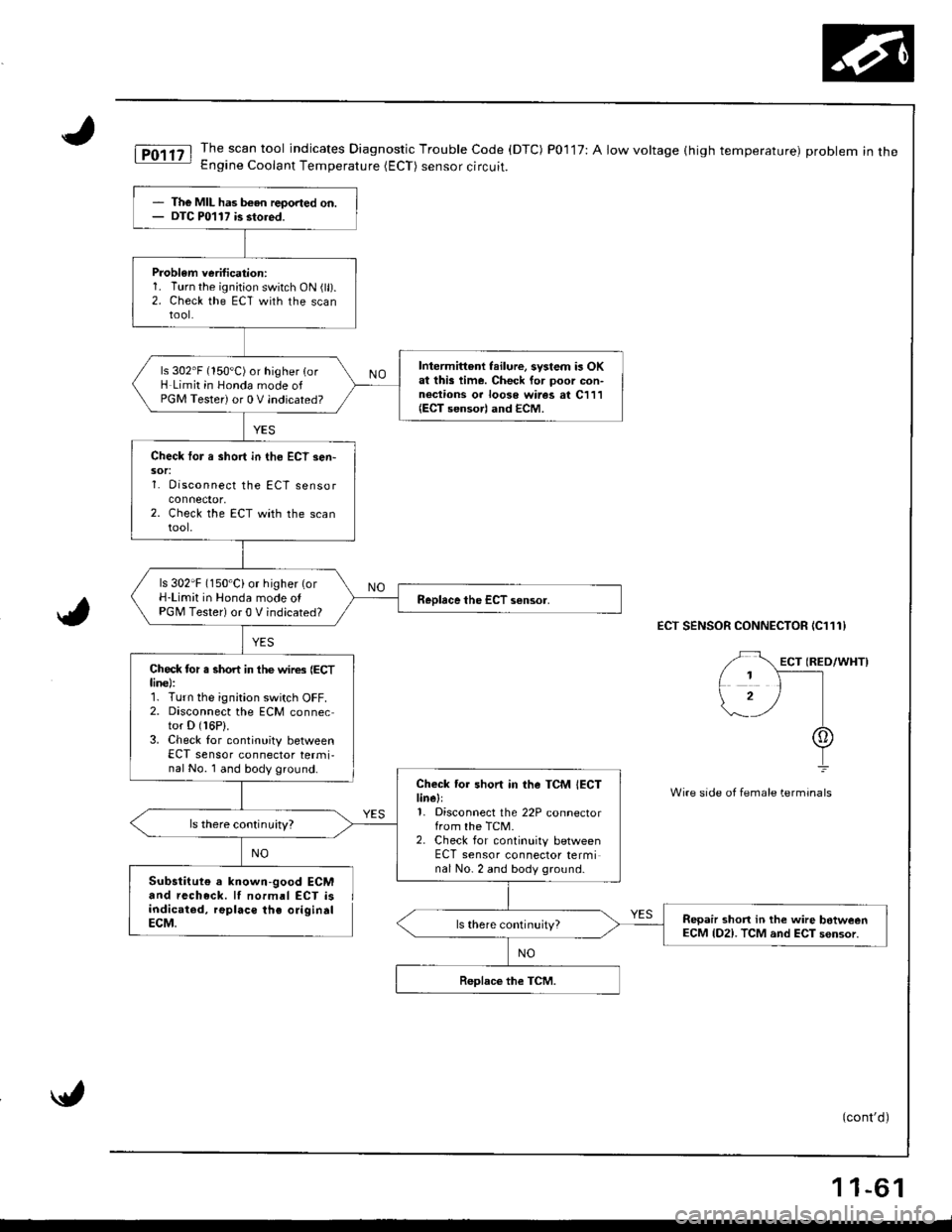
The MIL has b€en reoorted on.DTC P0117 is stored.
Problem verification:1. Turn the ignition switch ON (ll).2. Check the ECT with the scantool.
Intermittent failure, system is OKat this time. Check for poor con-nections or looso wires at C111(ECT sensorl and ECM.
ls 302'F (150'C) or higher {orH Limit in Honda mode ofPGM Tester) or 0 V indicated?
Check tor a short in tho ECT sen-sor:1. Disconnect the ECT sensor
2. Check the ECT with the scantool.
ls 302'F (150'Ci or higher (orH-Limit in Honda mode olPGM Tester) or 0 V indicated?
Check tor s short in the wires (ECTline):r. r urn Ine rgnrtron swttch uFf,2. Disconnect the ECM connector D (16P).
3. Check lor continuity betweenECT sensor connector termi,nal No. 1 and body ground.
Check tor short in the TCM IECTlinell1, Disconnect the 22P connectorfrom the TCM.2. Check for continuity betweenECT sensor connector terminal No- 2 and body ground.
ls there continuity?
Repair shon in the wire botweenECM lD2). TCM and ECT sensor.
iT,011tl The.scan tool indicates Diagnostic Trouble Code (DTC) P0117:Alowvoltage(hightemperature) probleminthe- Engine Coolant Temperature (ECT) sensor circuit.
ECT SENSOR CONNECTOR IC111}
Wire side of fem6le terminals
Substitute a known-good ECMand recheck. lI normal ECT isindicated, replaco the origindlECM.
(cont'd)
NO
11-61
Page 267 of 1681
\
r
I
Ir
PGM.FI
Engine
System
Coolant Temperature (ECTI Sensor (cont'dl
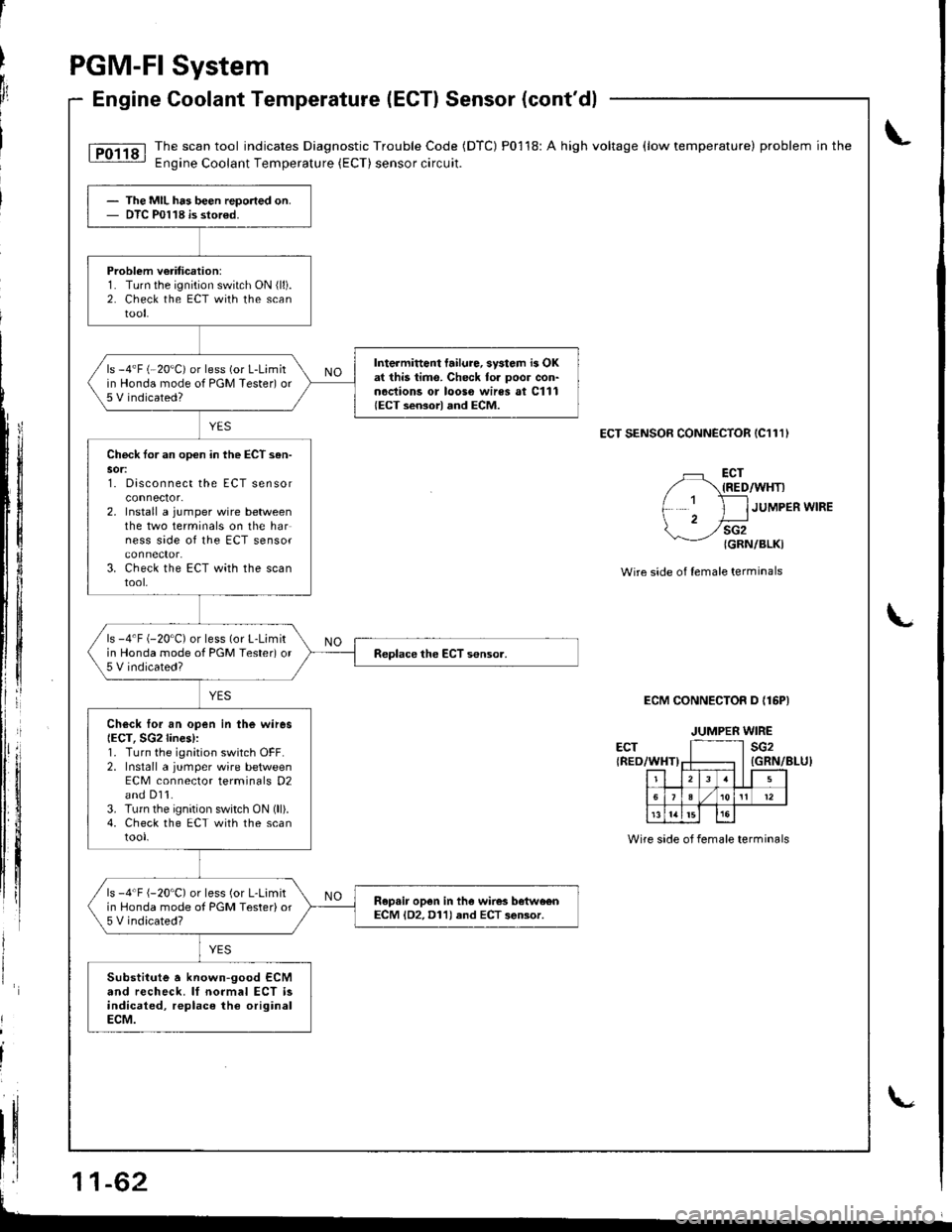
lTo1ig I The.scan tool indicates Diagnostic Trouble Code (DTC) P01 18: A high voltage (low temperature) problem in the.- Engine Coolant Temperature (ECT) sensorcircuit.
ECT SENSOR CONNECTOR (C111)
L
li
li
tllll
tl
fl
ECT{RED/WHT)
sG2{GRN/BLKI
JUMPER WIRE
Wire side o{ lemale terminals
ECM CONNECTOR D {16PI
ECT{RED/WHT)
The MIL has been repo.ted on.DTC P0118 is stor€d.
Problem v€riticetion:1. Turn the ignition switch ON (ll).
2. Check the ECT with the scantool.
Intermittont failure, svstom i3 OKat this time. Check for poor con-noctions or looso wires at C111{ECT sensorl and ECM.
ls -4'F (-20"C) or less (or L-Limitin Honda mode of PGM Tester) or5 V indicated?
Chock tor an opon in the ECT s6n-sor:t. utsconnect tne EL I sensor
2. Install a jumper wire betweenthe two terminals on the harness side of the ECT sensor
3. Check the ECT with the scantool,
ls -4'F (-20"C) or less (or L-Limitin Honda mode of PGM Tested or5 V indicated?
Ch6ck Ior an open in the wiresIECT, SG2lines):1. Turn the ignition switch OFF.2. Install a jumper wire betweenECM conneclor terminals D2and D11.3. Turn the ignition switch ON (ll).4. Check the ECT with the scantool.
ls -4'F {-20'C) or less (or L-Limitin Honda mode ol PGM Tester) or5 V indicated?
Ropair op6n in the wires betwo€nECM lD2, D11) and ECT 3eBor.
Substitute a known-good ECMand recheck. lf normal ECT isindicated, replace the originalECM.
JUMPER WIRE
sG2
r-zlr r5
5e I/ 101t't2
l5
Wire side of female terminals
L
Page 302 of 1681
2.
1.
1.
2.
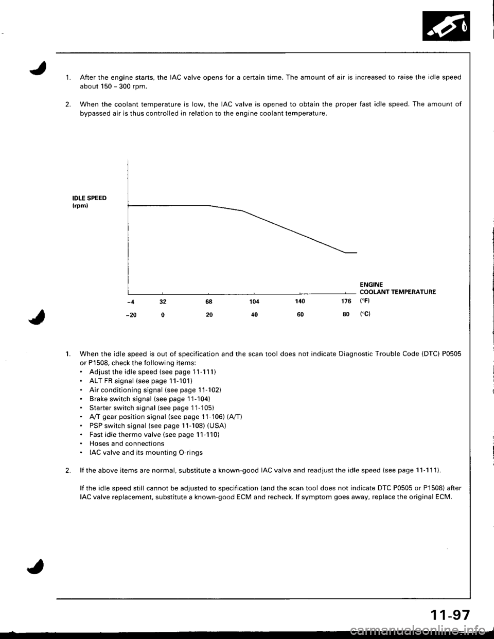
After the engine stans, the IAC valve opens for a certain time. The amount ol air is increased to raise the idle speed
about 150 - 300 rpm.
When the coolant temperature is low, the IAC valve is opened to obtain the proper fast idle speed. The amount of
bypassed air is thus controlled in relation to the engine coolant temperature.
IDLE SPEEDtrpm,
ENGINECOOLANT TEMPERATURE
140
50
104
40
-1 32
-20 0
176 ('F)
80 fcl
When the idle speed is out of specification and the scan tool does not indicate Diagnostic Trouble Code (DTC) P0505
or P'1508, check the following items:. Adiust the idle speed (see page '11-111)
' ALT FR signal (see page 11-101). Air conditioning signal {seepage'11-102)' Brake switch signal (seepagell-104)
. Starter switch signal (see page 11-1051. A,4 gear position signal (see page 1l 106) (A"/T)
. PSP switch signal (see page 11-108) (USA)
. Fast idle thermo valve (see page 11-110). Hoses and connections. IAC valve and its mounting O rings
ll the above items are normal, substitute a known-good IAC valve and readjust the idle speed (see page 'l I -1 1 l).
lf the idle speed still cannot be adjusted to specification (and the scan tool does not indicate DTC P0505 or P1508) after
IAC valve replacement, substitute a known-good ECM and recheck. lf symptom goes away, replace the original ECM.
11-97
Page 315 of 1681
ldle Control System
Fast ldle Thermo Valve (A/T model onlylFast ldle I nermo valve (A/ | mooel
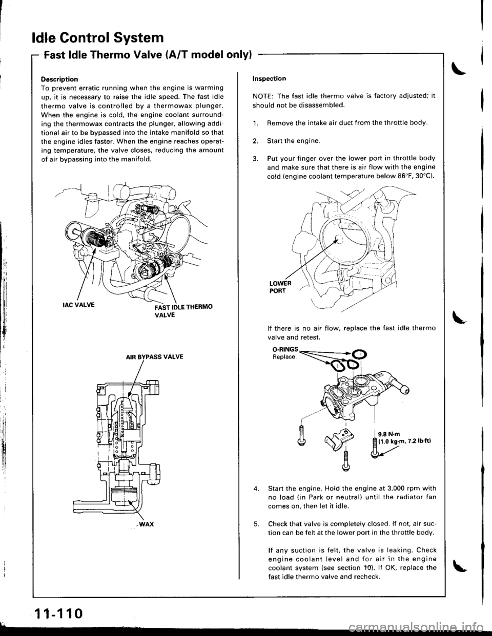
Description
To prevent erratic running when the engine is warming
up. it is necessary to raise the idle speed. The fast idle
thermo valve is controlled by a thermowax plunger.
When the engine is cold, the engine coolant surround-
ing the thermowax contracts the plunger, allowing addi
tional air to be bvoassed into the intake manifold so that
the engine idles taster. When the engine reaches operat-
ing temperature, the valve closes. reducing the amount
of air bypassing into the manifold.
FAST IDLE THERMO
VALVE
VALVE
wAx
Inspection
NOTE: The fast idle thermo valve is factory adiusted; it
should not be disassembled.
1. Remove the intake air duct from the throttle body.
2. Start the engine.
3. Put your finger over the lower port in throttle body
and make sure that there is air flow with the engine
cold {engine coolant temperature below 86'F, 30"c).
LOWERPORT
lf there is no air flow, replace the last idle thermo
valve and retest.
Start the engine. Hold the engine at 3,000 rpm with
no load (in Park or neutral) until the radiator fan
comes on, then let it idle.
Check that valve is completely closed. lf not, air suc-
tion can be felt at the lower port in the throttle body.
l{ any suction is felt, the valve is leaking. Check
engine coolant level and for air in the engine
coolant system (see section 10). It OK, replace the
fast idle thermo valve and recheck.
5.
{1.0 kg.m,7.2lbftl
l
11-110
lL.�
Page 437 of 1681
Description
Elestronic Control System (cont'd)
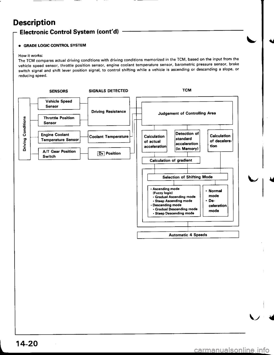
. GRADE LOGIC CONTROL SYSTEM
How it works:
The TCM compares actual driving conditions with driving conditions memorized in the TCM. based on th€ input from the
vehicle speed sensor, throttle position sensor, engine coolant temperature sensor, barometric pressure sensor, bral(e
switch signal and shift lever position signal, to control shifting while a vehicle is ascending or descending a slope, or
reducing speed.
SIGNALS DETECTED
{l
{
Driving ResistanceJudgement of Controlling Aroa
. Ascending mode(Fuzzy logicl. Gl.dual Ascending mode' Steop Asconding mode' oesconding mode. Gradu.l D$conding modo. Slecp D$conding modo
\-t {t
Page 464 of 1681
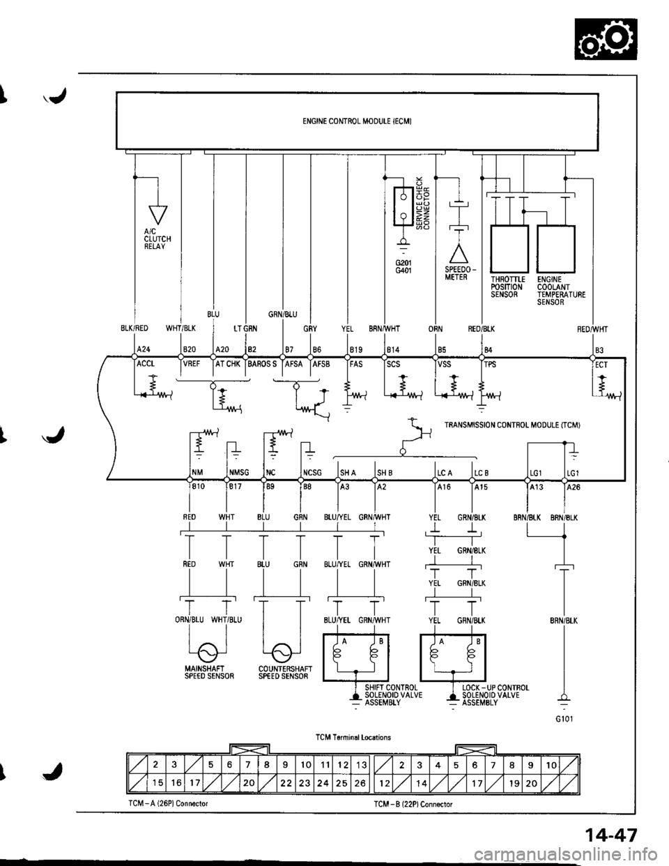
'.J
THROTTLErcsm0NSENSOR
ENGINECOOLANTTEMPERATURESENSOR
WHT/BLKBLK/RED
820424
OBNREO/BLK
84
J
MAINSHAFI COUNTERSHAFISPEED SENSOR SPfED SENSOR
I SHIFT CONTROL I LOCK -UP CONTBOL
+135Eil,?1o'uo'u' 4i85El,o''P'uo'u'
TCM T6nninal locations
TCM -B l22P)Conn€ctor
VREF IATCHK IBASOSS IAFSA IAFSB IFAS ISCS
----T;- t-T-*
+.. | +.., I + ,+
l+ | J l/vt-l .i{-'1M-l L-{-lr^/t-lt't'/!-?
*\::
r--rr!\.1 -r!\./ rartsurssrot coNTFoL M'DULE tTcMr
ltEltn r' -rrt= t= t? t=
NMSG INC INCSG ISH A ISH B ILC A ILC B
576I101112578I10
151617,/1,/20251214,/1,/171920,/1,/J
TCM -A (26P1 Connector
14-47
Page 466 of 1681
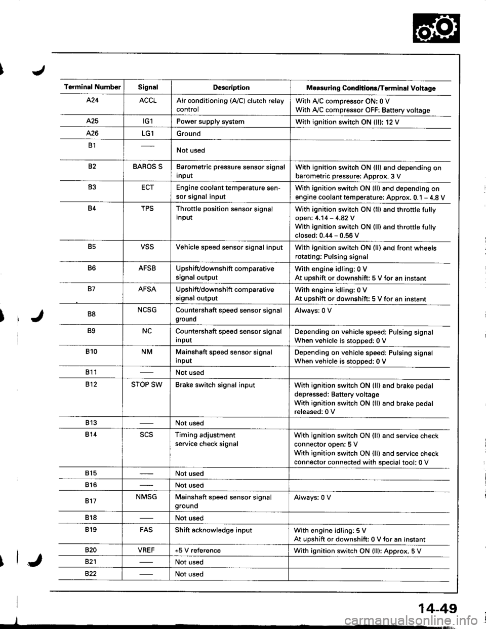
Terminal NumberSignalDescriptionMaasuring Conditlons/Tarminal Voliage
424ACCLAir conditioning (Ay'C) clutch relay
control
With A,/C comDressor ON: 0 V
With Ay'C compressor OFF: Battery voltage
A25tG1Power supply systemWith ignition switch ON (ll)r 12 V
426LG1Ground
B1Not used
82BAROS SBarometric pressure sensor signal
input
With ignition switch ON (ll) and depending on
barometric pressure: Approx. 3 V
B3ECTEngine coolant temperature sen-
sor signal input
With ignition switch ON (ll) and depending on
engine coolant tem perature: Approx. 0.1 - 4.8 V
B4TPSThrottle position sensor signal
input
With ignition switch ON (ll) 8nd throttle fully
open: 4.14 - 4.82 V
With ignition switch ON (ll) and throttle fully
closed: 0.44 - 0.56 V
B5VSSVehicle speed sensor signal inputWith ignition switch ON (ll) and front wheels
rotating; Pulsing signal
B6AFSBUpshifvdownshift comparative
signal output
With engine idling: 0 V
At uDshift or downshift: 5 V for an instant
B7AFSAUpshifvdownshift com parative
srgnal output
With engine idling: 0 V
At upshift or downshift: 5 V for an instant
B8NCSGCountershaft speed sensor signal
ground
Always: 0 V
B9NCCountershaft speed sensor signal
Input
Depending on vehicle speed: Pulsing signal
When vehicle is stopped:0 V
B10NMMainshaft speed sensor signal
input
Depending on vehicle speed: Pulsing signal
When vehicle is stoDoed: 0 V
811Not used
812STOP SWBrake switch signal inputWith ignition switch ON {ll) and b.ake pedal
depressed: Battery voltage
With ignition switch ON (lll and brake pedal
released:0 V
813Not used
814scsTiming adjustment
service check signal
With ignition switch ON (ll) and service check
connector oDen:5 V
With ignition switch ON (ll) and service check
connector connected with special tool: 0 V
815Not used
816Not used
817NMSGMainshaft speed sensor signalgroundAlways: 0 V
818Not used
819FASShift acknowledge inputWith engine idling: 5 V
At upshift or downshift: 0 V for an instant
820VBEF+5 V referenceWith ignition switch ON {lll: Approx. 5 V
82'lNot used
Not used
14-49