fog light HONDA INTEGRA 1998 4.G User Guide
[x] Cancel search | Manufacturer: HONDA, Model Year: 1998, Model line: INTEGRA, Model: HONDA INTEGRA 1998 4.GPages: 1681, PDF Size: 54.22 MB
Page 1106 of 1681
T
I
1
J)
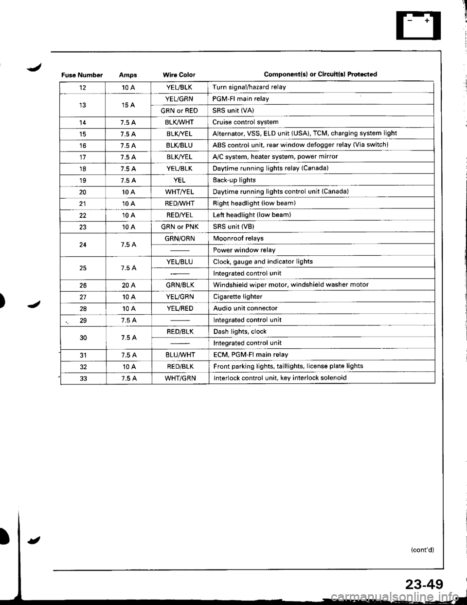
Fuso NumberWire ColorComponent{s} or Circuit(rl ftqt6cted
't210AYEUBLKTurn signal/hazard relay
15 AYEUGRNPGM-Fl main relay
GRN or REDSRS unit (VA)
147.5 ABLK/WHTCruise control system
15BLK/YE LAlternator, VSS, ELD unit (USA), TCM, charging system light
't67.5 ABLVBLUABS control unit, rear window defogger relay (Via switch)
117.5 ABLK//ELAVC system, heater system, power marror
187.5 AYEUBLKDaytime running lights relay (Canada)
197.5 AYELEack-up lights
2010 AWHT/YELDaytime running lights control unit (Canada)
2110 ARED/WHTRight headlight (low beam)
2210 ARE D|YE LLett headlight (low beam)
2310 AGRN or PNKSRS unit (VB)
247.5 AGRN/ORNMoonroof relays
Power window relay
7.5 AYEUBLUClock, gauge and indicator lights
Integrated control unit
2620AGRN/BLKWindshield wiper motor, windshield washer motor
10AYEUGRNCigarette lighter
2810AYEUREDAudio unit connector
29Integrated control unit
30RED/BLKDash lights, clock
Integrated control unit
317.5 A8LU/WHTECM. PGM-Fl main relav
10ARE D/BLKFront parking lights, taillights, license plate lights
7.5 AWHT/GRNInterlock control unit, key interlock solenoid
23-49
Page 1110 of 1681
J
)1 -
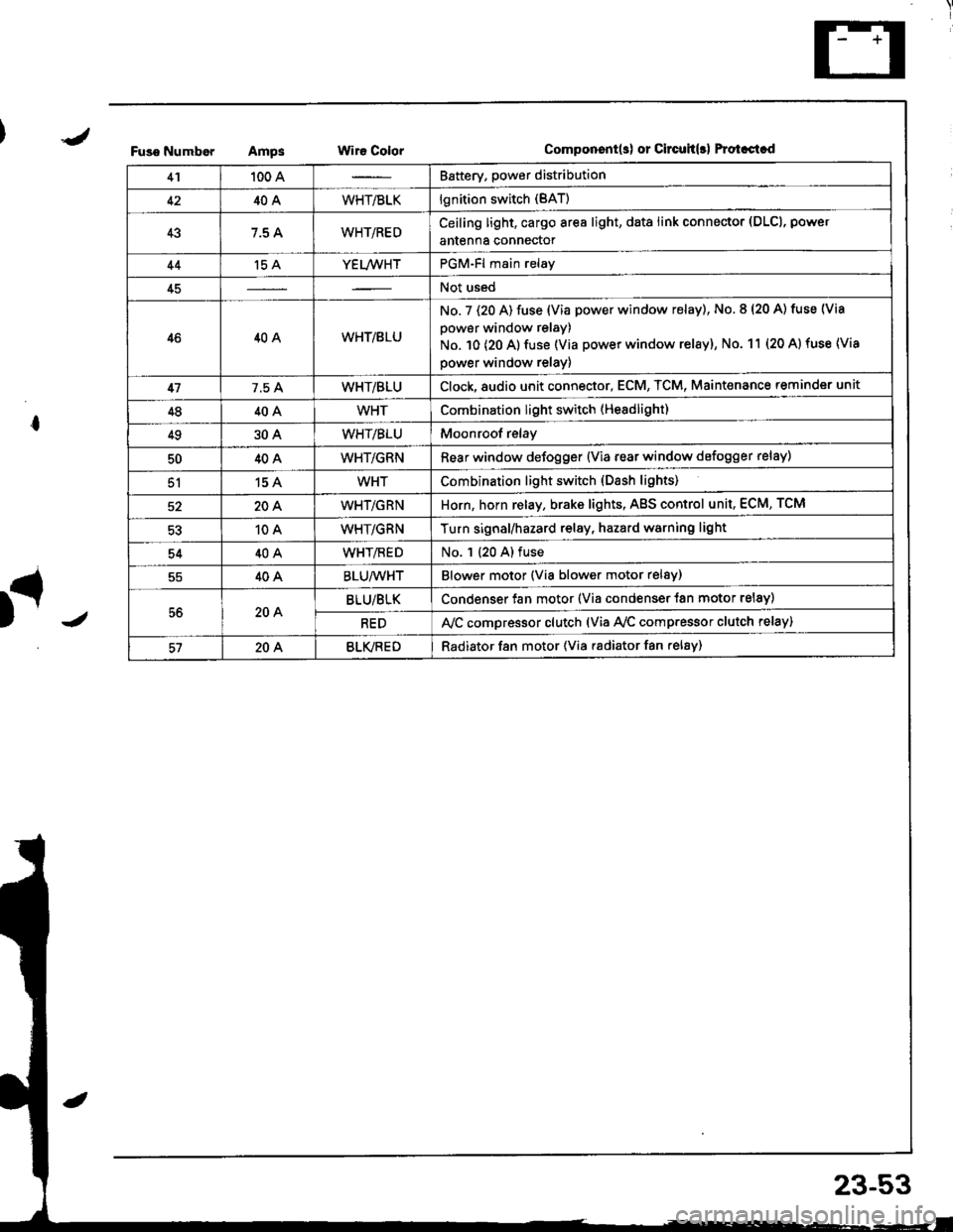
Fuso NumborAmpsWir€ ColorComponent(s) or Circuh(rl Protastcd
41100 ABattery. power distribution
4240AWHT/BLKlgnition switch (BAT)
437.5 AWHT/REDCeiling light, cargo area light, data link connector (DLCl, power
antenna connector
44't5 AYEL/WHTPGM-Fl main relay
45Not used
4640AWHT/8LU
No. 7 (20 A) fuse (Via power window relay), No. 8 (20 A) tuse (Via
power window relay)
No. 10 (20 A) fuse (Via power window relay), No. 11 (20 A) fuse (Via
power window relay)
417.5 AWHT/BLUClock,8udio unit connector, ECM, TCM, Maint€nance reminder unit
4840AWHTCombination light switch (Headlight)
4930AWHT/BLUMoonroof relay
5040AWHT/GRNRear window defogger {Via rear window defogger relay)
51154WHTCombination light switch (Dash lights)
20AWHT/GRNHorn, horn relay, brake lights, AgS control unit, ECM, TCM
10AWHT/GRNTurn signal/hazard relay, hazard warning light
5440AWHT/flEDNo. 1 (20 A) fuse
40ABLU/WHTBlower motor (Via blower motor relsy)
56204BLU/BLKCondenser fan motor (Via condenser {an motor relay)
REDA,/C compressor clutch (via Ay'c comp.essor clutch relay)
57204BLVREDRadiator f8n motor (Via radiator fan relay)
23-53
Page 1209 of 1681
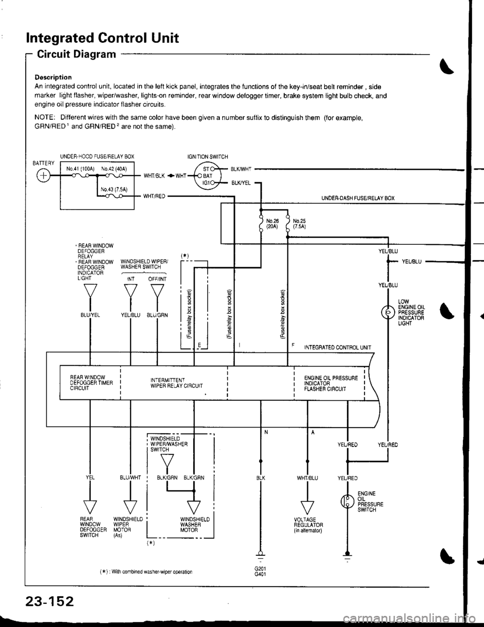
Integrated Control Unit
Circuit Diagram
Description
An integrated control unit, located in lhe left kick panel, integrates the lunctions of the key-in/seat belt r€minder , side
marker light llasher, wiper/washer, lights-on reminder, rear window delogger timer, brake system light bulb check, and
engine oil pressure indicator flasher circuits.
NOTE: Different wires with the same color have been given a nu mber suflix to distinguish them (for example,
GRN/RED I and GRN/RED'� are not the same).
REAR WINDOWDEFOGGERRELAYREAF WINDOWDEFOGGENIND CATORL GHT
f-7
IIBLU/YEL
WHT/ BLK
WHT/ REO
+WHT
WNDSHIELDWIPERiWASHER SWITCH
INT OFF/INT
f7 f7
tltlYEUBLU 8LU/GRN
BLUMHT
J
wtN0sHr€10WIPERMOTOR
UNDER.DASH FUSARETAY BOX
F rmecnlleo counoL ultr
YEUBLU
rYEUBLU
YEUREO YEUREO
tl
IYEURED
LOWENGINEOIIPRESSUREINOICATOBLIGHT
; WINDSHIELD' WIPERMASHERI swlTcH
tf7IVtlYEL
J
FEARwtN00wOEFOGGERSWITCH
WHTIBLU
J
VOTTAGEREGULATOR(ln allernatol)
BLK
G441
ENGINEolLPRESSUREswrTcH
UNDER-NOOO FUSE/RELAY BOX
1.6
:6
t;t-L
i
"'i'- 'i*-
|
I Il
I vi: WINDSHIELO II WASHEB I
L__ "oto: _ __l(*)
n
s
s
,]
23-152
(*) :Wilh combined washer-wiper operalion
Page 1212 of 1681
A B C D *E F G
YEL/BLU
View from wire side
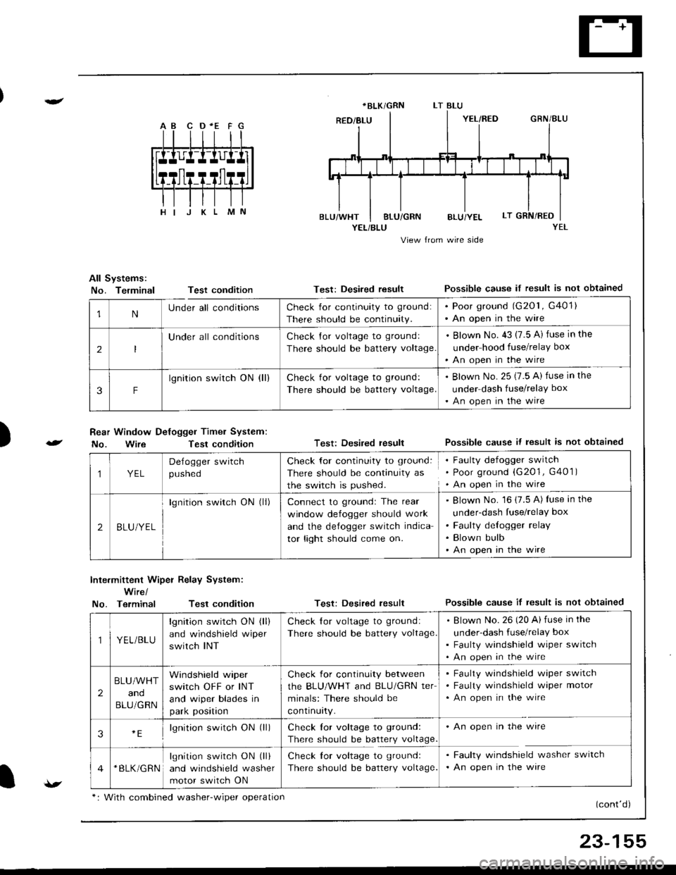
All Systems:
No. TerminalTest condition
Rear Window Defogger Timel System:
No. WireTest condition
Test: Desired resultPossible cause if result is not obtained
Test: Desired resultPossible cause it lesult is not obtained
Test: Desired resultPossible cause if result is not obtained
(cont'd)
)
Inte.mittent Wiper Relay System:
Wire/
No. TerminalTest condition
*BLK/GRN
1NUnder all conditionsCheck for continuity to ground:
There should be continuity.
. Poor ground (G201, G401). An open in the wire
2
Under all conditionsCheck Jor voltage to groundl
There should be battery voltage
. Blown No. 43 (7.5 A) fuse in the
under hood fuse/relay box
'An open in the wire
3F
lgnition switch ON (ll)Check for voltage to ground:
There should be battery voltage.
. Blown No. 25 (7.5 A) fuse in the
under dash fuse/relay box
. An open in the wire
1YEL
Delogger switch
pusneo
Check for continuity to ground:
There should be continuity as
the switch is pushed.
Faulty defogger switch
Poor ground (G201, G401 )
An open in the wire
2BLU/YEL
lgnition switch ON (ll)Connect to groundr The rear
window defogger should work
and the defogger switch indica
tor light should come on.
Blown No. 16 (7.5 A) fuse in the
under-dash fuse/relay box
Faulty delogger relay
Blown bulb
An open in the wire
YEL/BLU
lgnition switch ON (ll)
and windshield wiper
switch INT
Check lor voltage to ground:
There should be battery voltage
Blown No.26 (20 Ai fuse in the
under-dash fuse/relay box
Faulty windshield wiper switch
An open in the wire
2
BLU/WHT
and
BLU/GRN
Windshield wiper
switch OFF or INT
and wiper blades in
park position
Check for continuity between
the BLU/WHT and BLU/GRN ter
minals: There should be
contrnurty.
Faulty windshield wiper switch
Faulty windshield wiper motor
An open in the wire
3lgnition switch ON (ll)Check lor voltage to ground:
There should be battery voltage
An open in the wire
*BLK/GRNlgnition switch ON (ll)
and windshield washer
motor switch ON
Check lor voltage to ground:
There should be battery voltage.
Faulty windshield washer switch
An open in the ware
v*: With combined washer-wiper oDeration
23-155
Page 1235 of 1681
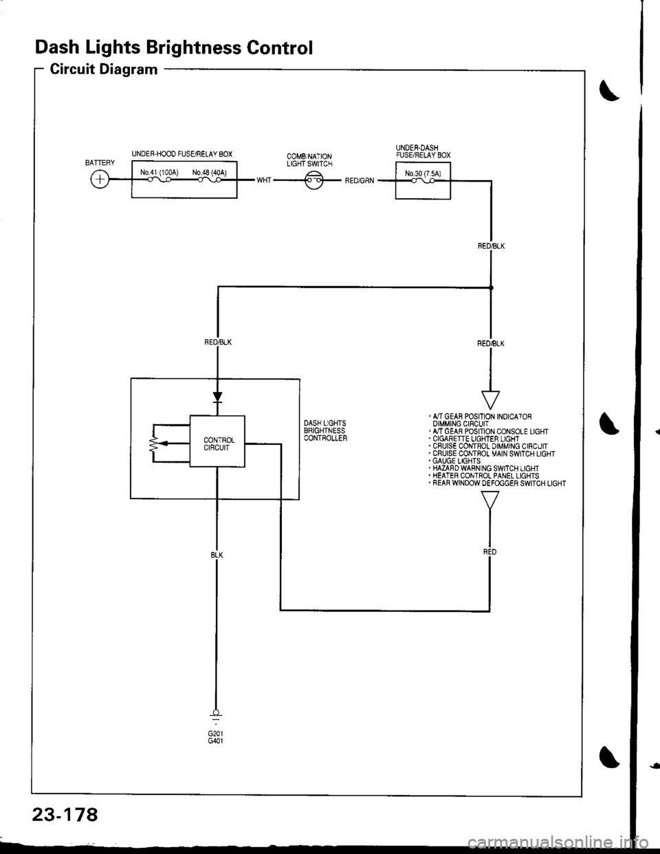
Dash Lights Brightness Control
Circuit Diagram
UNDER-HOOO FUSgRELAY 8OXUNDEN.DASHFUSE/RELAYEOXtX"f -.------^-;^*;;ilLrcrTswrc.
ffiwHT-lf-FEDGaN
, &TGEAN POSITION INOICATOROIMMING CIFCUIT.ATTGEAB POSITION CONSOLE LIGHT
. CRUISE COI,{TROL DIMMING CIRCUIT.CRUISE CONTHOT MAIN SWITCH LIGHT.GAUGE LIGHTS.HAZAFDWABN NG SWITCH LIGHT. HEATER CONTROL PANEL LIGHTS. REAR WINDOW DEFOGGER SWITCH LIGHT
23-178
Page 1271 of 1681
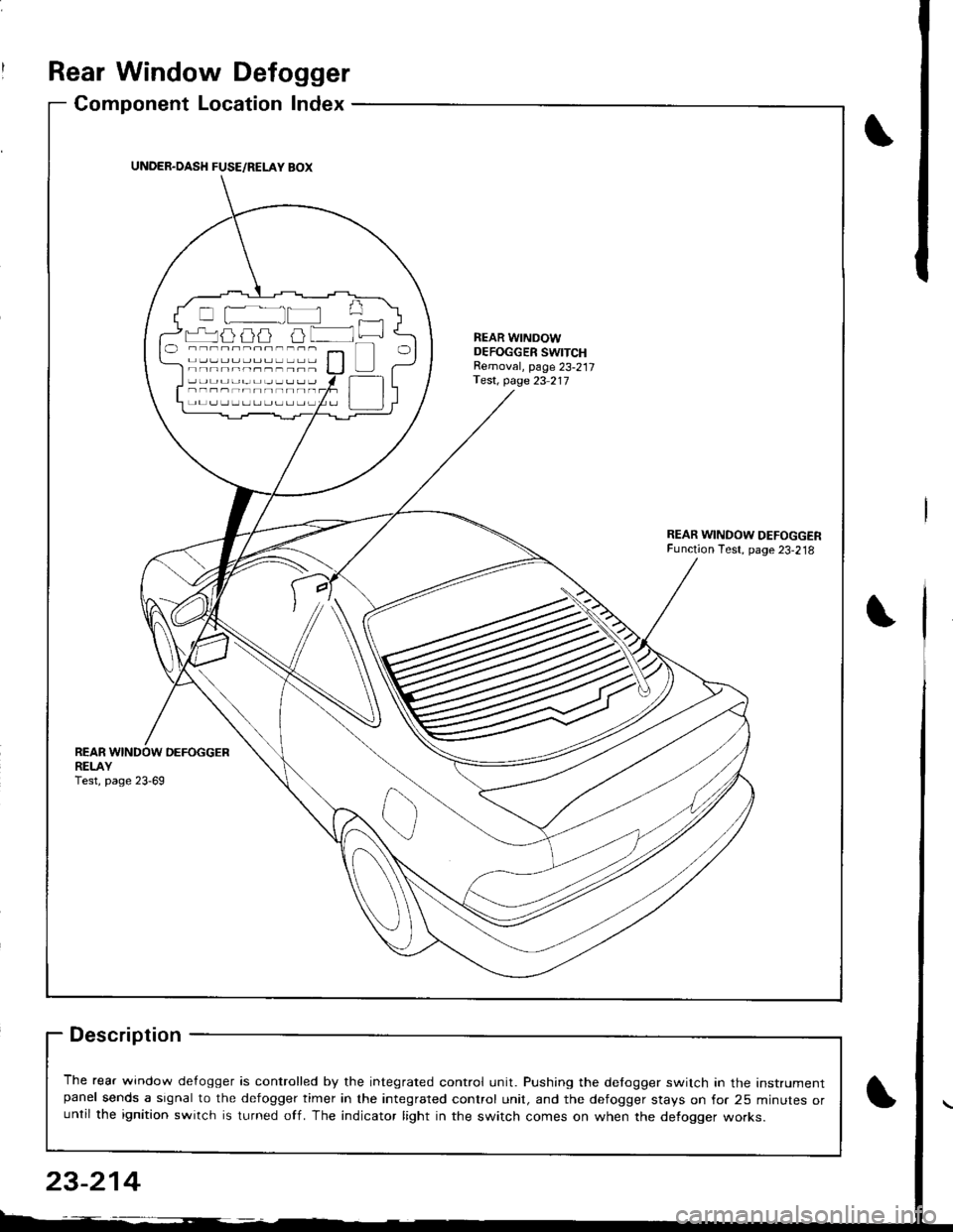
Rear Window Defogger
Component Location Index
Description
The rear window de{ogger is controlled by the integrated control unit. Pushing the detogger switch in the Instrumentpanel sends a signal to the defogger timer in the integrated control unit, and the defogger stays on for 25 minutes oruntil the ignition switch is turned off. The indicator light in the switch comes on when the defogger works.
UNDER.OASH FUSE/RELAY BOX
r-'luijij u lNEAR WINDOWDEFOGGER SWITCHRemoval, page 23-217Test, page 23 217
REARDEFOGGERREI-AYTest, page 23-69
23-214
Page 1272 of 1681
![HONDA INTEGRA 1998 4.G User Guide Circuit Diagram
REARwtNDowDEFOGGERSWITCH
BLK
IIJ
DASH LIGHTSBR CHTNESSCONTROLLER
CN TIONswrTcH
/ 8AT \
T ",7-l
II
II
WNT/BLK + WHT
REARWiNDOWDEFOGGER
BtK/GRN
--lELKGRN BLI(RED
1A
T L-]
ll
tl
tl
tl-l
U HONDA INTEGRA 1998 4.G User Guide Circuit Diagram
REARwtNDowDEFOGGERSWITCH
BLK
IIJ
DASH LIGHTSBR CHTNESSCONTROLLER
CN TIONswrTcH
/ 8AT \
T ",7-l
II
II
WNT/BLK + WHT
REARWiNDOWDEFOGGER
BtK/GRN
--lELKGRN BLI(RED
1A
T L-]
ll
tl
tl
tl-l
U](/img/13/6069/w960_6069-1271.png)
Circuit Diagram
REARwtNDowDEFOGGERSWITCH
BLK
IIJ
DASH LIGHTSBR CHTNESSCONTROLLER
CN TIONswrTcH
/ 8AT \
T ",7-l
II
II
WNT/BLK + WHT
REARWiNDOWDEFOGGER
BtK/GRN
--lELKGRN BLI(RED
1A
T L-]
ll
tl
tl
tl-l
UNDEF HOOD FUSE/RELAY BOX
No41 (100A) N0.42 (40A)
G201G401G201G40lHatchback:G771Sedan iG503I
23-215
Page 1273 of 1681
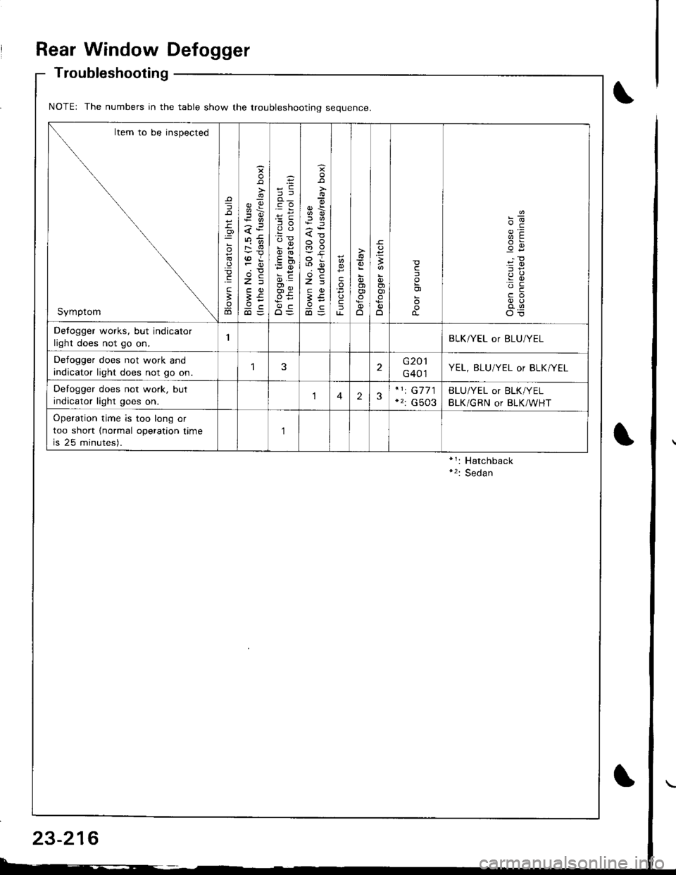
Rear Window Defogger
Troubleshooting
NOTEr The numbers in the table show the troubleshootino seouence
Item to be inspected
Symptom
=
o
.9
.E
;
ao
o
s
;!i6
<:
FO
>=
;€9c
';i !
oi
O=
{o
a5
3tr
ta
fu-o
,
OJo)
o
c
'-c
Defogger works, but indicator
light does not go on.BLK/YEL or BLU/YEL
Defogger does not work and
indicator light does not go on.3G201
G401YEL, BLU/YEL or BLK/YEL
Defogger does not work, but
indicator light goes on.123G7 71
G503
BLU/YEL or BLK/YEL
BLK/GRN or BLK/WHT
Operation time is too long or
too short (normal operation time
is 25 minutes).
,]
23-216
Page 1275 of 1681
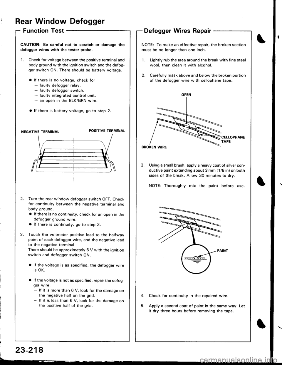
Rear Window Defogger
Function TestDefogger Wires Repair
I
I
CAUTION: Be caretul not to scratch or damage the
defogger wires with the tester probe,
1. Check tor voltage between the positive terminal and
body ground with the ignition switch and the defog-
ger switch ON. There should be battery voltage.
lf there is no voltage, check for
faulty defogger relay.- faulty defogger switch.- faulty integrated control unit.- an open in the BLK/GRN wire.
lf there is battery voltage, go to step 2.
NEGATIVE TERMINALPOSITIVE TEFMINAL
2.Turn the rear window defogger switch OFF. Check
for continuity between the negative terminal and
body ground.
a lf there is no continuity, check for an open in the
defogger ground wire.a lf there is continuity, go to step 3.
Touch the voltmeter positive lead to the halfwaypoint of each delogger wire, and the negative lead
to the negative terminal.
There should be approximately 6 V with the ignition
switch and defogger switch ON,
a lf the voltage is as specified, the defogger wire
is OK.
a lf the voltage is not as specified, repair the defog-ger wire:
lf it is more than 6 V, look for the damage on
the negative half on the grid.
lf it is less than 6 V, look for the damage onthe positive half of rhe grid.
3.
NOTE: To make an elfective repair, the broken section
must be no longer than one inch.
1 . Lightly rub the area around the break with fine steel
wool, then clean it with alcohol.
2. Carefully mask above and below the broken portion
of the defogger wire with cellophane tape.
CELLOPHANETAPE
BBOKEN WIRE
3, Using a small brush, apply a heavy coat of silver con-
ductive paint extending about 3 mm (l /8 in) on both
sides of the break. Allow 30 minutes to dry.
NOTE: Thoroughly mix the paint before use.
Check for continuity in the repaired wire.
Apply a second coat of paint in the same way.
it dry three hours before removing the tape.
Let
OPEN
23-214
Page 1383 of 1681
).1
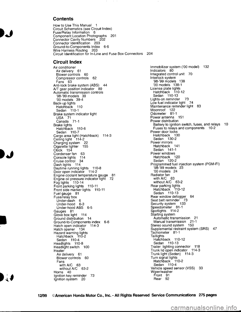
Contents
How to Use This l\.4anual 1Circuit Schematics (see Circuit Index)Fuse/Relaylnformation 6ComponentLocation Photographs 201
Connector Cavity Numbers 202Connectorldentification 203
Ground-to-Components Index 6-6Wire Harness Routing 203Circuit ldentification lor ln-Line and Fuse Box Connectors
Circuit Index
Air conditionerAir delivery 61Blower controls 60Compressor controls 62Fans 63Anti-lock brake system (ABS) 44A/T gear position indicator 89Automatic transmission controls'98199 models 39'00 models 39-4Back-up lightsHatchback 110Sedan 110- 1Brake system indicator light
USA 71Canada 71-1Brake lightsHatchback 110-6Sedan 110-7Cargo area light (Hatchback) 114-3Ceiling light 114-2Charging system 22Cigarette lighter 155
Clock 154Condenser fan 63Console lights 114Cruise control 34Dash lights 1 14Daytime running lights 110-8Door open indicator 114-2Engine coolant temperature gauge 81Engine oil pressure indicator light 72Fog lights 110-14Front parking lights 110-11Front side marker lights 110-11Fuel gauge 81Fuse/relay boxUnder-dash 6Under-hood 6-3Under-hood ABS 6-5Gauges 81Glove box light 114Ground distribution 14Ground-to-Componentsindex 6-6Hatch open indicator '114-3
Hatch opener '134
Hazard warning lightsHatchback 'l l0-2Sedan 110-4Headlights 1'10-8Headlight switch 100HeaterAir delivery 61Blower controls 60Fanswith A,/C 63without A,/C 63-2Horns 40lgnilion key reminder 73lgnition system 20
204
lmmobilizer system ('00 model) 132lndicators 80Integrated control unit 70Interlock system'98199 models 138'00 models 138-1License plate lightsHatchback 110-12Sedan 110-13Lights-on reminder 73Low fuel indicator light 74l\,4aintenance reminder light 83l\iloonroof 122Odometer 81-1Power antenna 151Power distributionBattery to ignilion switch, fuses, and relays
Fuses to relays and components 10-2Power door locksHatchback '130
Sedan 130-2Power mirrorsHatchback 141Sedan 141-1Power windowsHatchback 120Sedan 120-2Programmed fuel injection system (PGM-Fl)'98199 models 23'00 models 24Radiator fanwith tuC 63without A,/C 63-2Rear parking lightsHatchback 110-12Sedan 110- 13Rear window defogger 64Seat belt reminder 73Security system 133Speedometer Il-1Spotlights 114-2Starting syslemAutomalictransmission 21l\.4anualtransmission 21-1Stereo sound system 150Supplemental restraint system (SRS) 47Tachometer 81- 1TaillightsHatchback 110-12Sedan 110-13Trailer lighting conneclor 118Trunk lid open indicator 114-3Trunk light (Sedan) 114-3Turn signal lightsHatchback 110-2Sedan 110-4Vehicle speed sensor (VSS) 33Wiper/washerFront 91Rear 92
10
).1
I
Xr
12Fg oAmerican Honda Motor Co., Inc. - All Rights Reserved Service Communications 275 pages