horn HONDA INTEGRA 1998 4.G User Guide
[x] Cancel search | Manufacturer: HONDA, Model Year: 1998, Model line: INTEGRA, Model: HONDA INTEGRA 1998 4.GPages: 1681, PDF Size: 54.22 MB
Page 1127 of 1681
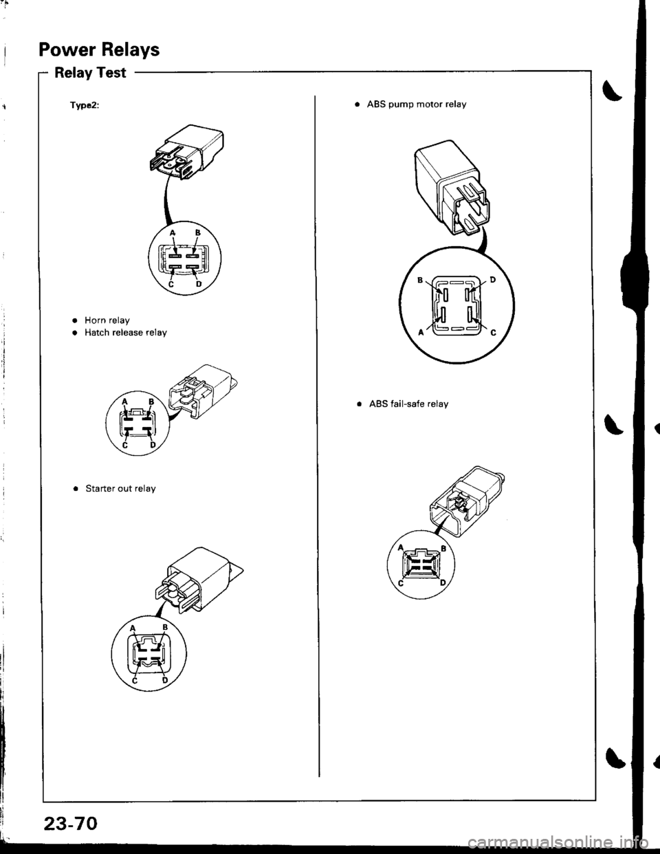
. Horn relay
a Hatch release relay
. Starter out relay
Power Relays
. ABS pump motor relay
. ABS fail-safe relay
Page 1264 of 1681
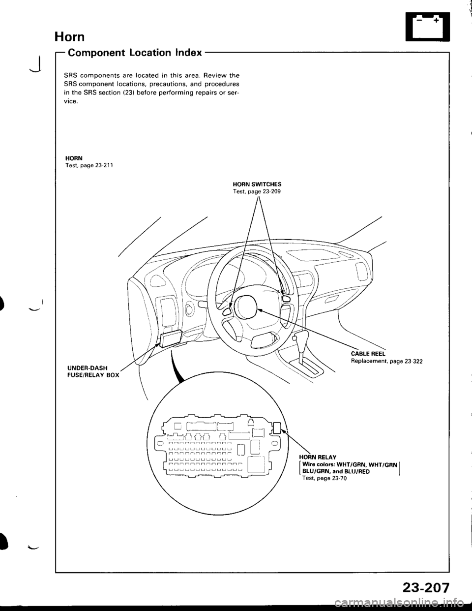
Horn
Component Location lndex
JSRS components are located in this area. Review the
SRS component locations, precautions, and procedures
in the SRS section {23) before performing repairs or ser-
vtce,
HORNTest, page 23 211
HORN SWITCHESTest, page 23-209
CABLE REELReplacement, page 23 322UNDER-DASHFUSE/BELAY BOX
{---=-\s":=',-i=
il
-rrj _LJLi lJJJ I -.r ----------;- - t--t -----,------- L I t---HORN RELAY
I Wire colo6: WHT/GRN, WHT/GRN ILBLU/GRN, and BLU/REO ITest, page 23-70
)
23-207
Page 1266 of 1681
SwitchTest
SRS comDonents are located in this area. Review the
SRS component locations, precautions, and procedures
in the SRS section (23) before performing repairs or ser-
vtce.
NOTE: The original radio has a coded thett protection cir-
cuit. Be sure to get the customer's code number beJore- disconnecting the battery.- removing the No. 47 (7.5 A) fuse from the under-hood
fuse/relay box.- removing the radio.
After service, reconnect Dower to the radio and turn it on.
When the word "CODE" is displayed, enter the customer's
5-digit code to restore radio operation
Disconnect the battery negative cable, then discon-
nect the positive cable, and wait at least three min-
uIes.
Disconnect each airbag connector.
Driver's Side:
a Remove the access panel from the steering wheel,
then disconnect the 2P connector between the
driver's airbag and cable reel.
Front Passenger's Side:
. Remove the glove box,
a Disconnect the 2P connector between the front
passenger's airbag and SRS main harness.
1.
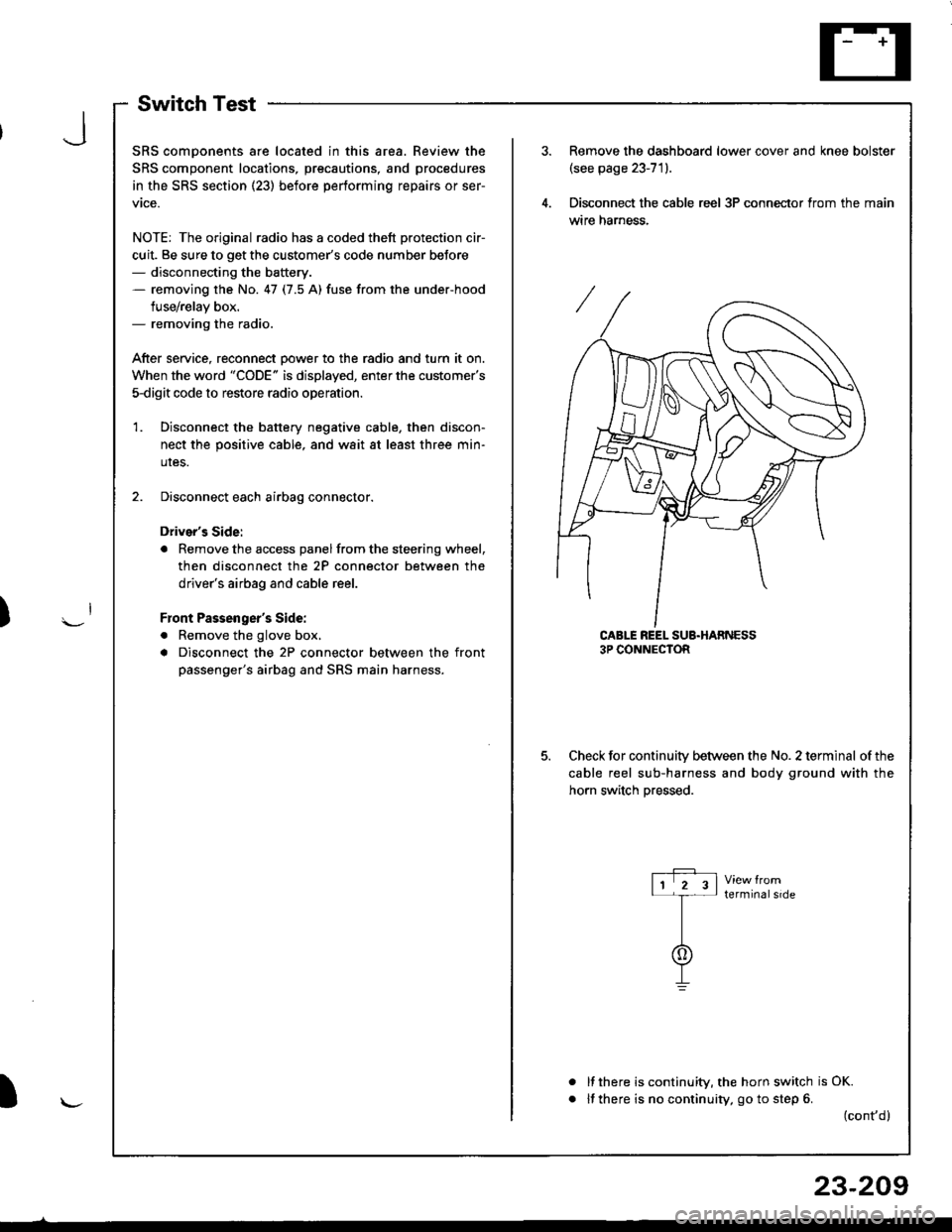
Remove the dashboard lower cover and knee bolster(see page 23-71).
Disconnect the cable reel 3P conneclor from the main
wtre narness.
CABLE REEL SUB.HARNESS3P CONNECTOR
Check for continuitv between the No. 2 terminal of the
cable reel sub-harness and body ground with the
horn switch Dressed.
terminalside
a
It there is continuity, the horn switch is OK.
lf there is no continuity, go to step 6. (cont,d)
r-P r11 2 3l-t-
I
I\-J
)
I
23-209
Page 1267 of 1681
Horn
Switch Test (cont'd)
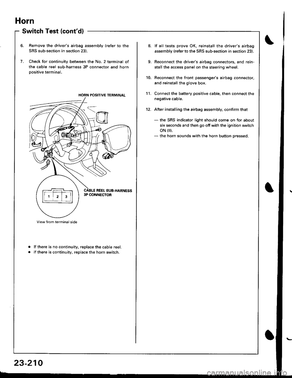
Remove the driver's airbag assembly (refer to the
SRS sub-section in section 23).
Check for continuity between the No. 2 terminal of
the cable reel sub-harness 3P connector and horn
Dositive terminal.
lf there is no continuity. replace the cable reel.
lf there is continuity, replace the horn switch.
a
a
HORN POSITIVE TERMINAL
23-210
9.
10.
11.
12.
lf all tests prove OK, reinstall the driver's airbag
assembly (re{er to the SRS sub-section in section 23).
Reconnect the driver's airbag connectors, and rein-
stall the access panel on the steering wheel.
Reconnect the front passenger's airbag connector,
and reinstall the glove box.
Connect the battery positive cable, then connect the
negative cable.
Atter installing the airbag assembly, confirm that
- the SRS indicator light should come on for about
six seconds and then go off with the ignition switch
oN 0t).- the horn sounds with the horn button pressed.
Page 1268 of 1681
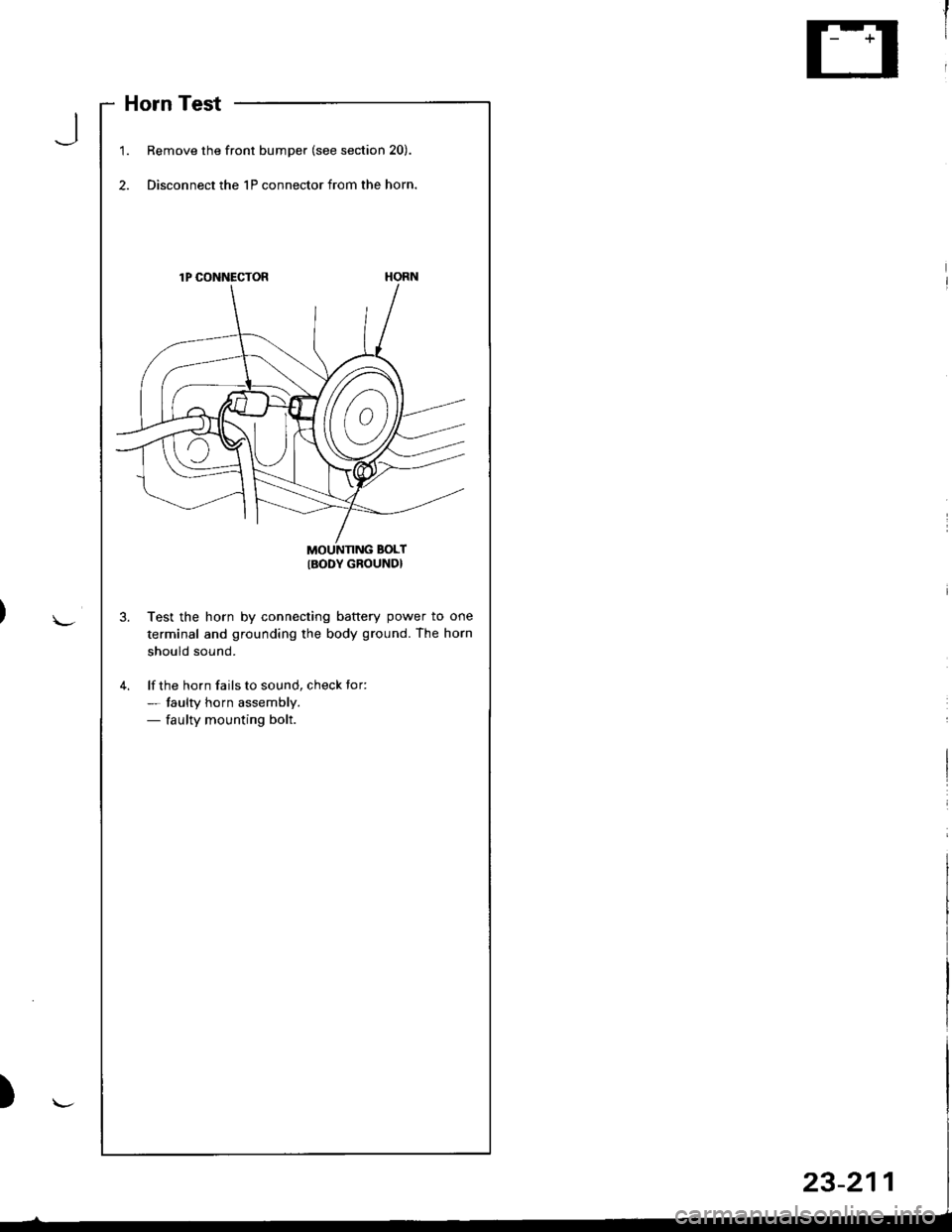
Horn Test
1.Remove the front bumper (see section 20).
Disconnect the 1P connector from the horn.
lP CONNECTOR
MOUNNNG BOLT
IBODY GROUND}
Test the horn by connecting battery power to one
terminal and grounding the body ground. The horn
should sound.
lf the horn fails to sound, check tor:- taulty horn assembly.- faulty mounting bolt.
J
Page 1311 of 1681
t
t;
i'l
I
dil
Gruise Gontrol
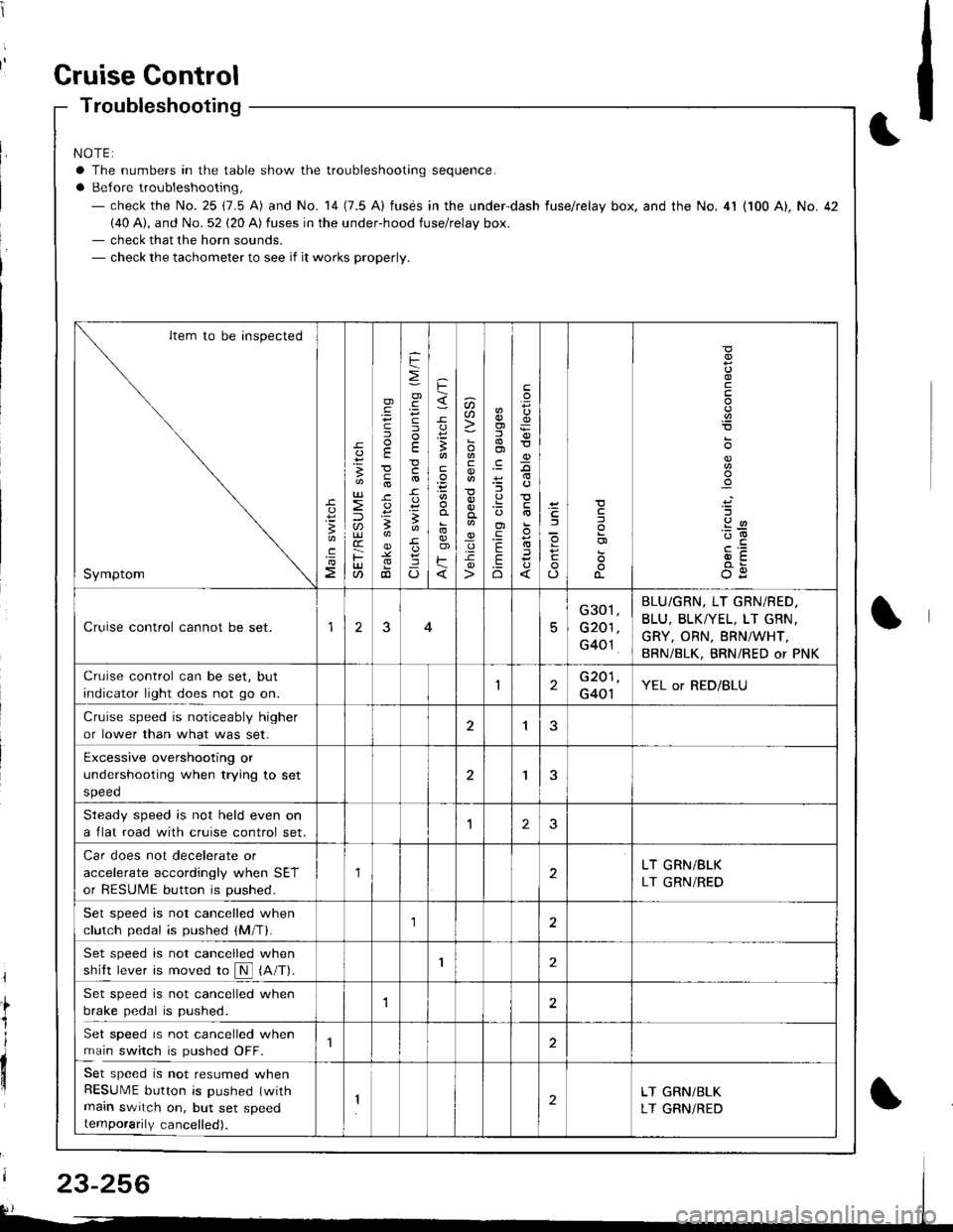
Troubleshooting
NOTE:
a The numbers in the table show the troubleshooting sequence.
a Belore troubleshooting,- check the No. 25 (7.5 A) and No. 14 (7.5 A) fusds in the under-dash fuse/relay box. and the No. 4l (100 A), No. 42(40 A), and No. 52 (20 A) fuses in the under-hood fuse/relay box.- check that the horn sounds.- check the tachometer to see if it works properly.
Item to be inspected
Symptom
c
:3
UJ
lU)(r
F(t
)
E
c
.
F
=
.g
E
-c
!-
Io
F
3
E
o)F
u)U'
co
_q.9-c
o)f,
ol
;l
E
.Eo
F
E
_9
)a
o
o-
o
c
.2
'::-c
OE
Cruise control cannot be set.15
G301
G201
G40't
BLU/GRN, LT GRN/RED.
BLU, BLKTYEL, LT GRN.
GRY, ORN, BRNiWHT,
BRN/BLK, BRNi RED or PNK
Cruise control can be set, but
indicator light does not go on.1G201
G401YEL or RED/BLU
Cruise speed is noticeably higher
or lower than what was set.1
Excessive overshooting or
undershooting when trying to set
speed
'I
Steadv soeed is not held even on
a flat road with cruise control set.1J
Car does not decelerate or
accelerate accordingly when SET
or RESUME button is pushed.
1LT GRN/BLK
LT GRN/RED
Set speed is not cancelled when
clutch pedal is pushed (M/T).1
Set speed is not cancelled when
shift lever is moved ro N (A/T).I
Set speed is not cancelled when
brake pedal is pushed.12
Set speed is not cancelled when
main switch is pushed OFF.
Set speed is not resumed whenRESUME button is pushed (with
main switch on, but set speedtemporarily cancelled).
2LT GRN/BLK
LT GRNiRED
23-256
Page 1332 of 1681
!
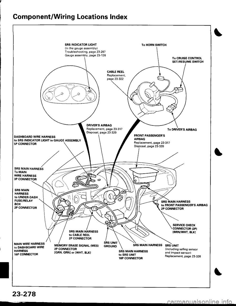
Gomponent/Wiring Locations Index
SRS INDICATOR LIGHT(ln the gauge assembly)Troubleshooting, page 23-287Gauge assembly, page 23-126
To HORN SWITCH
CABLE REELReplacement,page 23-322
DRIVER'S AIRBAGReplacement. page 23-317Disposal, page 23-320To DRIVER'S AIRBAG
DASHBOARD WIRE HARNESSFRONT PASSENGER'SAIRBAGBeplacement, page 23-317Disposal, page 23-320
to SRS INDICATOR LIGHT in GAUGE ASSEMBLY5P CONNECTOR
SRS MAIN HARNESSTo MAINWIRE HARNESS3P CONNECTOR
SRS MAINHARNESSto UNDER-DASHFUSE/RELAYBOX2P CONNECTOR
HARNESSto FRONT PASSENGERS AIRBAG2P CONNECTOR
SRS MAIN
SERVICE CHECXCONNECTOR {2PIIBRNAAIHT, BLK]to CABLE REEL2P CONNECTOR
MAIN WIRE HARNESSto DASHBOARD WIREHARNESS16P CONNECTOR
ERASE SIGNAL (MES}SRS UNITGBOUNOSRS MAIN HARNESSSRS UNIT(lncluding safing sensorano rmpact sensor)R6placement, page 23-326
2P CONNECTORSRS MAIN HARNESSto SRS UNIT18P CONNECTOR
S\--0
[GRN, GRNI or IWHT, BLKI
23-27A
Page 1373 of 1681
I
I
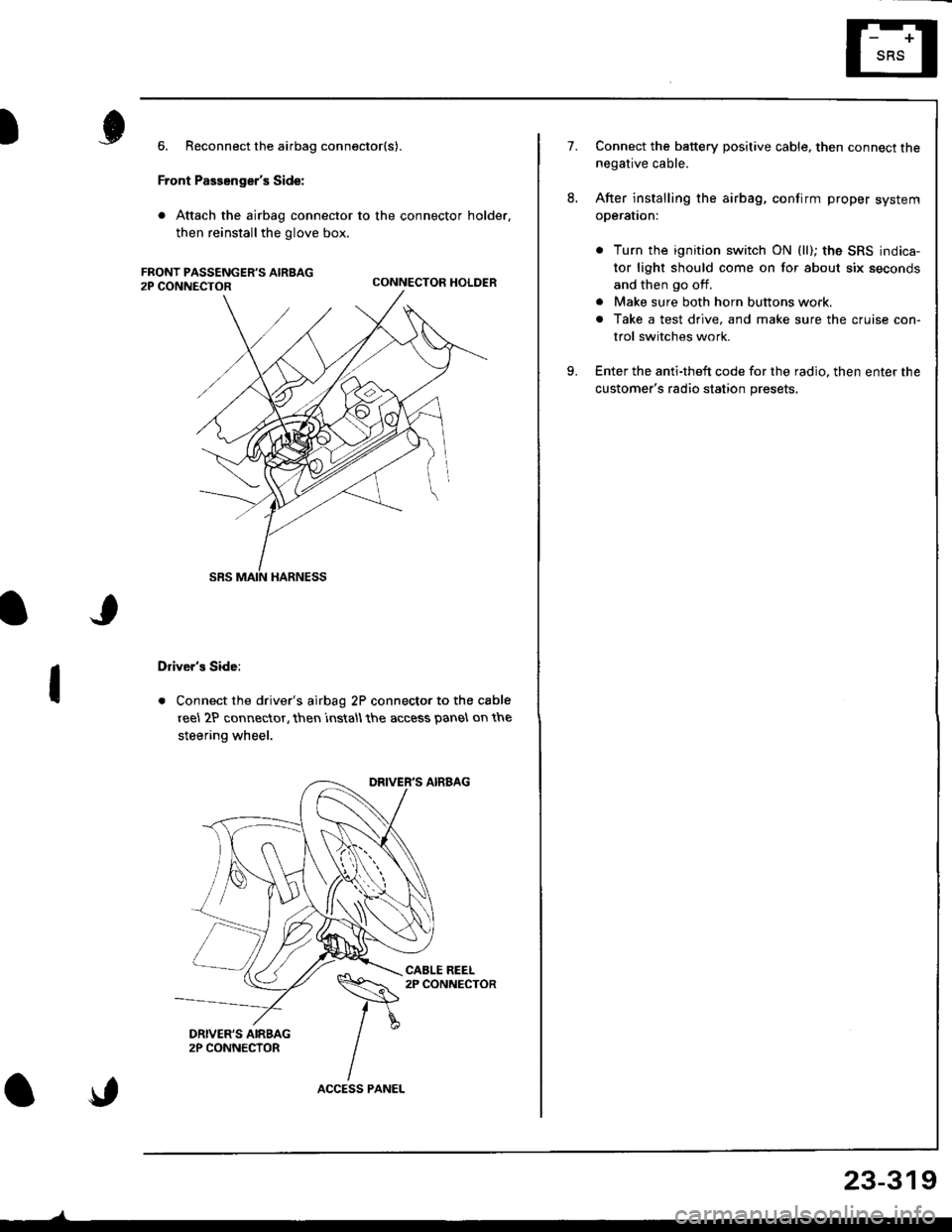
6. Reconnect the airbag connector(s).
Front Passenger's Side:
. Attach the airbag connector to the connector holder.
then reinstallthe glove box.
CONNECTOR HOLDER
Driver's Side:
. Connect the driver's airbag 2P connector to the cable
reel 2P connector, then rnstall the access panel on the
steering wheel.
\,
23-319
7.Connect the baftery positive cable, then connect thenegative cable.
After installing the airbag, confirm proper system
operal|on:
. Turn the ignition switch ON (ll); the SRS indica-
tor light should come on for about six seconds
and then go off.
. Make sure both horn buttons work.
. Take a test drive, and make sure the cruise con-
trol switches work.
Enter the anti-theft code for the radio. then enter the
customer's radio station presets,
9.
Page 1377 of 1681
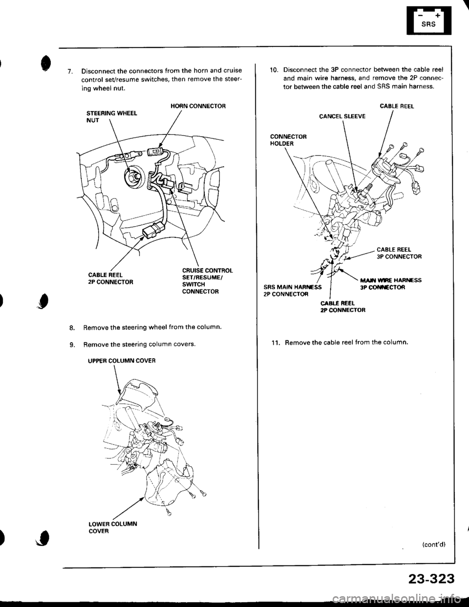
7.Disconnect the connectors from the horn and cruise
control sevresume switches, then remove the steer-
ing wheel nut.
Remove the steering wheel from the column.
Remove the steering column covers
UPPER COLUMN COVER
8.
)
HORN CONNECTOR
\
10.Disconnect the 3P connector between the cable reel
and main wire harness. and remove the 2P connec-
tor between the cable reel and SRS main harness.
CABLE BEEL
CABE R€EL2P CONNECTOR
'11. Remove the cable reel fromthecolumn.
(cont'd)
23-323
Page 1378 of 1681
Cable Reel
Replacement (cont'dl
CAUTION:
. Before installing the steering wheel, the lront
wheels should be aligned str8ight ahead.
. Be sure to install the harness wires so that they
are not pinched or interfering with other parts.
. After reassembly, confirm thal the wheels are
slill turned str8ight ahead and that the steering
wheel spoke angle is correst (road test). lf minol
spoke angle adjustment is necessary, do so only
by adiusting the tie-.ods, not by removing and
repositioning the steering wheel.
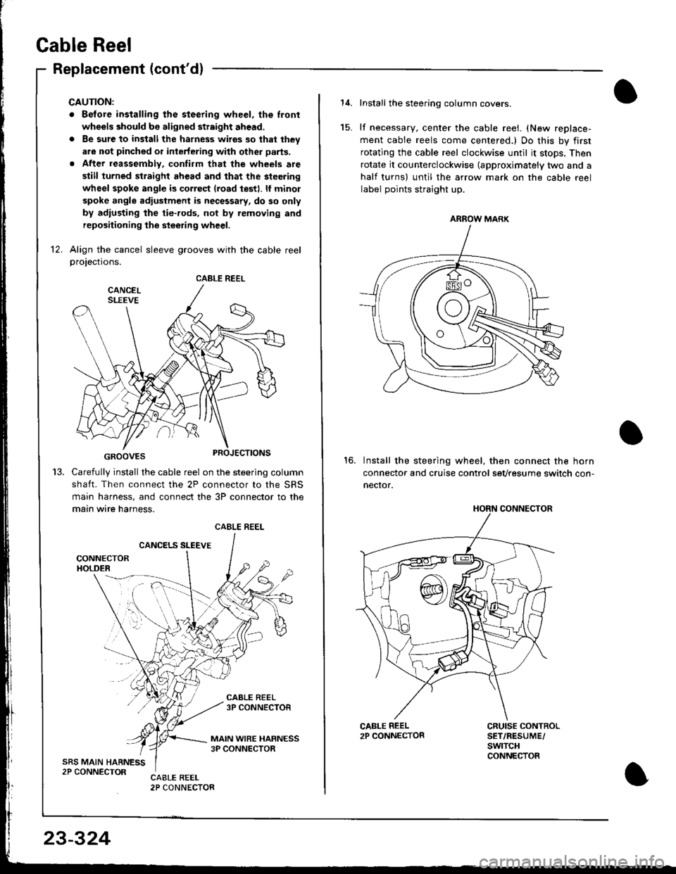
12. Align the cancel sleeve grooves with the cable reelprojections.
GROOVES
Carefully install the cable reel on the steering column
shaft. Then connect the 2P connector to the SRS
main harness, and connect the 3P connector to the
main wire harness.
CANCELS SLEEVE
CABLE REEL
13.
CABLE REEL
23-324
Install the steering column covers.
lf necessary, center the cable reei. (New replace-
ment cable reels come centered.) Do this by first
rotating the cable reel clockwise until it stops. Then
rotate it counterclockwise (approximately two and a
half turns) untll the arrow mark on the cable reel
label points straight up.
Install the steering wheel, then connect the horn
connector and cruise control sevtesume switch con-
necror.
15.
16.
CRUISE CONTROLSET/RESUME/swtTcHCONNECTOR
ARROW MARK
HORN CONNECTOR