relay HONDA INTEGRA 1998 4.G Workshop Manual
[x] Cancel search | Manufacturer: HONDA, Model Year: 1998, Model line: INTEGRA, Model: HONDA INTEGRA 1998 4.GPages: 1681, PDF Size: 54.22 MB
Page 1346 of 1681
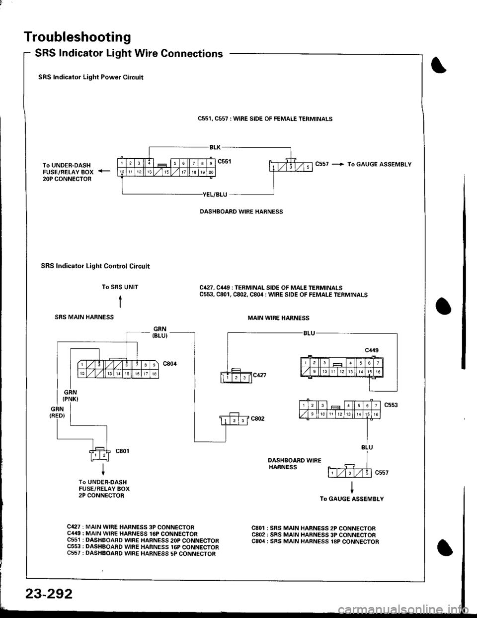
Troubleshooting
SRS Indicator Light Wire Connections
SRS Indicator Light Power Circuit
To UNDER-DASHFUSE/RELAY BOX2OP CONNECTOB
SRS Indicator Light Control Circuit
To SBS UNIT
iI
SRS MAIN HABNESS
C55'1, C557 : WIRE SIDE OF FEMALE TERMINALS
DASHBOARD WIRE HARNESS
MAIN WIRE HARNESS
C557 -+ To GAUGE ASSEMBLY
CiP7, C449 : TERMINAL SIDE OF MALE TERMINALSC553, CEo1. C802, C804: WIBE SIDE OF FEMALE TEFMINALS
DASHBOAND WIREHARNESS
To UNOEF-DASHFUSE/RELAY BOX2P CONNECTOR
C427 : MAIN WIRE HARNESS 3P CONNECTORC/r49 : MAIN WIBE HARNESS 16P CONNECTORC551 : DASHSOARD WIRE HARNESS 2Op CONNECTORC553 : DASHBOARD WIFE HARNESS t6P CONNECTORCssT : OASHBOARD WlnE HABNESS SP CONNECTOB
To GAUGE ASSEMBLY
C801 : SRS MAIN HARNESS 2P CONNECTOBC802 : SRS MAIN HARNESS 3P CONNECTORC804: SRS MAIN HAFNESS 18P CONNECTOR
BLU
Page 1347 of 1681
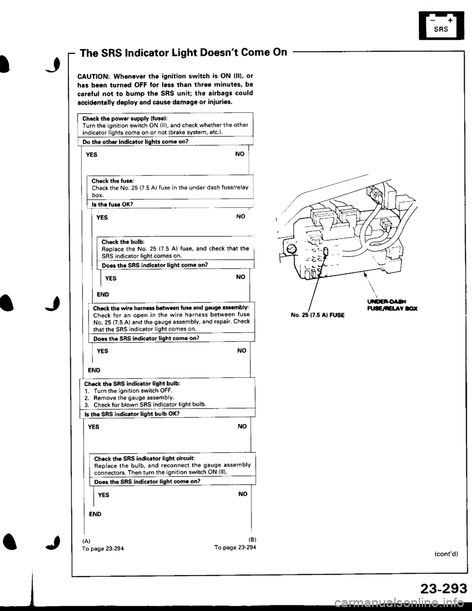
The SRS Indicator Light Doesnt Come On
CAUTION: Whenever the ignition switch is ON (lll, ol
has been turned OFF tor lsss than three minutes. be
careful not to bump the SRS unit; the airbags could
accidentslly deploy and cause damage or iniuries.
Chcck tho power supply lfuso):Turn the ignition switch ON (ll), and check whether the other
indicator lights come on or not (brake system, etc.).
Do tho oth6J indicator ligh$ come on?
NO'ES
Check ths tuse:Check the No. 25 (7.5 Ai fuse in the under dash fuse/relayho!
ls th. tu.o OK?
YESNO
Chsck the bulb:Replace the No. 25 17.5 A) fuse, and check that the
SRS indicator light comes on.
Doos tho SRS indic.lor light como on?
YES
END
Ch.ck th6 wir€ ham€ls b€twoen fu3e snd gauge .3sembly:
Check for an open in the wire harness belween tuse
No. 25 (7.5 A) and the gauge sssembly, and repair. Check
that the sRS indicator light comes on.
Doo3 the SRS indicator light come on?
YES
NO
NO
END
Ch6ck tho SRS indicator light bulb:
1. Turn the ignition switch OFF.2. Remove the gauge assemblY3. Check tor blown SRS indicator light bulb.
b tho sRs indicrlor light bulb oK?
YESNO
Check tho SRS indicator ligln circuit:ReDlace the bulb, and reconnect the gauge assembly
connectors. Then turn the ignition switch ON (ll).
Do.s tho SRS indicrtor light comG on?
I vrs NoII
END
No. 25 lt.5 Al FUSE
{A)fo page 23-294
(B)
10 page 23-294(cont'd)
Page 1350 of 1681
Troubleshooting
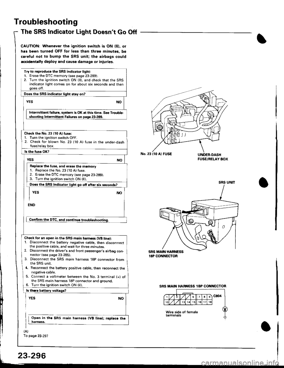
The SRS Indicator Light Doesnt Go Off
CAUTIOi{: Whenever the ignition switch is ON (ll). or
h.s bGGn turned OFF for less than three minutes. be
crrclul noi to bump the SRS unit; the airbags could
lcci{tcntrlly deploy and cause damage or iniuries.
(A)
1o page 23-297
Try to reproduce the SRS indic.tor l;ght;l. Erase the DTC memory (see page 23-289).2. Turn the ignition switch ON (ll), and check that the SRSandicator light comes on lor about six seconds and thenooes off,
Ooes the SRS indicetor light stay on?
NOYES
Intermittc t failu.e, sydem is OK dt this time. Sec Troublo-shooting lntermitteirt Failuros on p.qe 23-28!1.
Check tho No. 23 {10 A) fuse:1. Turn the ignition switch OFF-2. Check for blown No. 23 110 A) fuse in the unde.dashfuse/relay box.
ls the luse OK?
YESNO
Roplsce the f!se, and eresc the memory1. Replace the No. 23 (10 Alfuse.2. Erase the DTC memory (see page 23-289).3. Turn the ignition switch ON (ll).
Does th6 SRS indicator light go off after rix socond6?
I YEs No
I
ENO
Contilm the DTC, and continuo troubleshooting.
Check tor an open in ths SRS main hlrna3r (VB tinc):1- Disconnect the battery negative cable. thon disconnectthe positive cable, and wait tor three mrnures.2. Disconnect the driver's and front passenger's airbag con-nector (see page 23 285).3. Disconnect the SRS main harness 18P connector fromthe SRS unit.a. Reconnect the battery positive cable, then reconnect thenegative cable.5. Connect a voltmeter between the No. 3 terminal (+) otthe SRS main harness 18P connector and ground.6. Turn the ignition switch ON {ll).
ls th.re bettery vohaqe?
YES
Open in th. SRS msin h.rness (VB linc); roptrca tha
NO
No.23110 Al FUSEUNOER.DASHFUSE/RELAY AOX
SRS UNIT
SRS MAIN HARI{ESS 18P COI{I{ECTOR
Page 1383 of 1681
).1
Contents
How to Use This l\.4anual 1Circuit Schematics (see Circuit Index)Fuse/Relaylnformation 6ComponentLocation Photographs 201
Connector Cavity Numbers 202Connectorldentification 203
Ground-to-Components Index 6-6Wire Harness Routing 203Circuit ldentification lor ln-Line and Fuse Box Connectors
Circuit Index
Air conditionerAir delivery 61Blower controls 60Compressor controls 62Fans 63Anti-lock brake system (ABS) 44A/T gear position indicator 89Automatic transmission controls'98199 models 39'00 models 39-4Back-up lightsHatchback 110Sedan 110- 1Brake system indicator light
USA 71Canada 71-1Brake lightsHatchback 110-6Sedan 110-7Cargo area light (Hatchback) 114-3Ceiling light 114-2Charging system 22Cigarette lighter 155
Clock 154Condenser fan 63Console lights 114Cruise control 34Dash lights 1 14Daytime running lights 110-8Door open indicator 114-2Engine coolant temperature gauge 81Engine oil pressure indicator light 72Fog lights 110-14Front parking lights 110-11Front side marker lights 110-11Fuel gauge 81Fuse/relay boxUnder-dash 6Under-hood 6-3Under-hood ABS 6-5Gauges 81Glove box light 114Ground distribution 14Ground-to-Componentsindex 6-6Hatch open indicator '114-3
Hatch opener '134
Hazard warning lightsHatchback 'l l0-2Sedan 110-4Headlights 1'10-8Headlight switch 100HeaterAir delivery 61Blower controls 60Fanswith A,/C 63without A,/C 63-2Horns 40lgnilion key reminder 73lgnition system 20
204
lmmobilizer system ('00 model) 132lndicators 80Integrated control unit 70Interlock system'98199 models 138'00 models 138-1License plate lightsHatchback 110-12Sedan 110-13Lights-on reminder 73Low fuel indicator light 74l\,4aintenance reminder light 83l\iloonroof 122Odometer 81-1Power antenna 151Power distributionBattery to ignilion switch, fuses, and relays
Fuses to relays and components 10-2Power door locksHatchback '130
Sedan 130-2Power mirrorsHatchback 141Sedan 141-1Power windowsHatchback 120Sedan 120-2Programmed fuel injection system (PGM-Fl)'98199 models 23'00 models 24Radiator fanwith tuC 63without A,/C 63-2Rear parking lightsHatchback 110-12Sedan 110- 13Rear window defogger 64Seat belt reminder 73Security system 133Speedometer Il-1Spotlights 114-2Starting syslemAutomalictransmission 21l\.4anualtransmission 21-1Stereo sound system 150Supplemental restraint system (SRS) 47Tachometer 81- 1TaillightsHatchback 110-12Sedan 110-13Trailer lighting conneclor 118Trunk lid open indicator 114-3Trunk light (Sedan) 114-3Turn signal lightsHatchback 110-2Sedan 110-4Vehicle speed sensor (VSS) 33Wiper/washerFront 91Rear 92
10
).1
I
Xr
12Fg oAmerican Honda Motor Co., Inc. - All Rights Reserved Service Communications 275 pages
Page 1385 of 1681
How To Use This Manual
Circuit Schematics
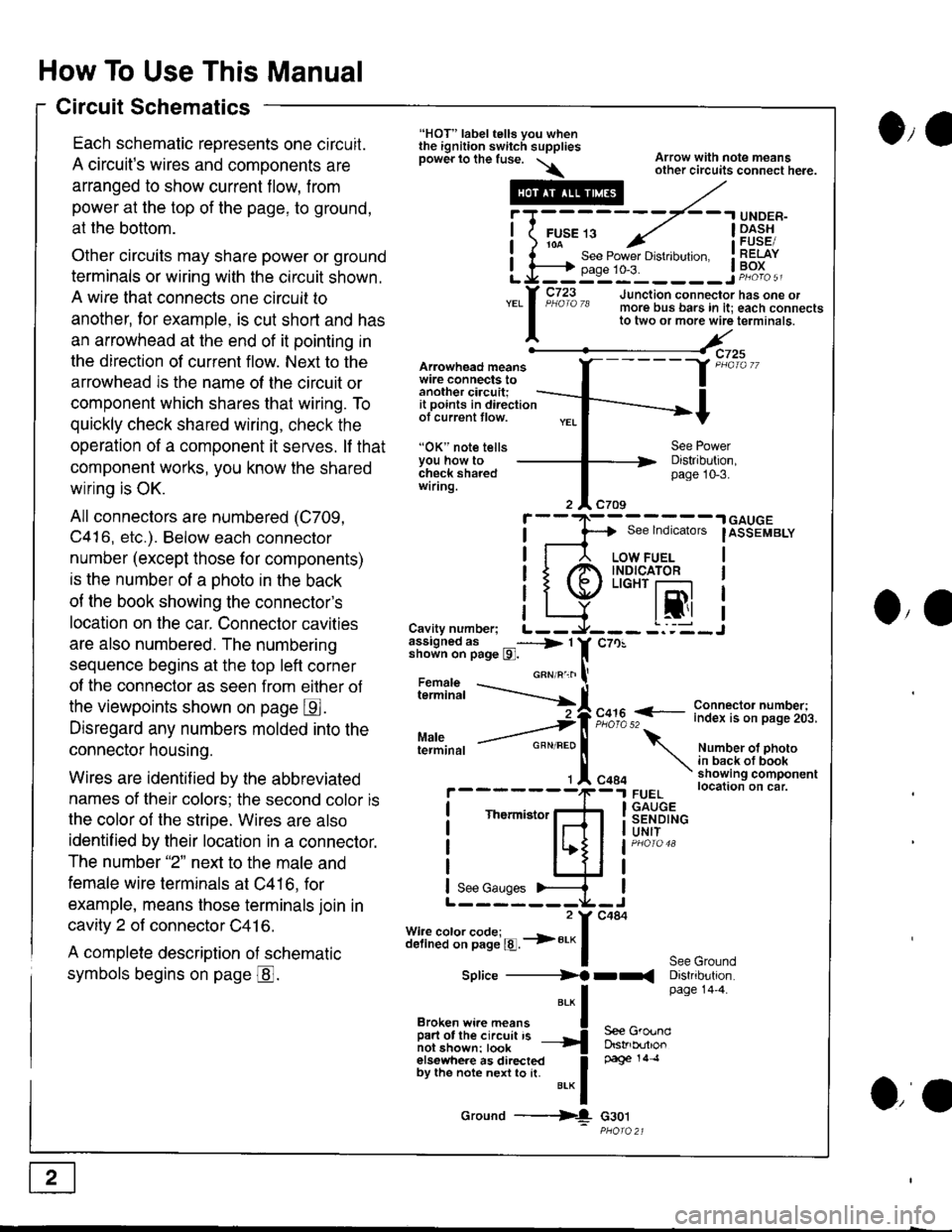
Each schematic reoresents one circuit.
A circuit's wires and components are
arranged to show current flow, from
power at the top of the page, to ground,
at the bottom.
Other circuits may share power or ground
terminals or wiring with the circuit shown.
A wire that connects one circuit to
another, lor example, is cut short and has
an arrowhead at the end of it pointing in
the direction of current flow. Next to the
arrowhead is the name ol the circuit or
component which shares that wiring. To
quickly check shared wiring, check the
operation of a component it serves. lf that
component works, you know the shared
wiring is OK.
All connectors are numbered (C709,
C416, etc.). Below each connector
number (except those for components)
is the number of a ohoto in the back
of the book showing the connector's
location on the car. Connector cavities
are also numbered. The numbering
sequence begins at the top left corner
of the connector as seen from eilher of
the viewpoints shown on page E.
Disregard any numbers molded into the
connector housing.
Wires are identif ied by the abbreviated
names of their colors; the second color is
the color of the stripe. Wires are also
identif ied by their location in a connector.
The number "2" next to the male and
female wire terminals at C416, for
example, means those terminals join in
cavity 2 of connector C41 6.
A complete description of schematic
symbols begins on page @.
O,e
Arowhead meanswire connects toanother ciacuit;it points in directionof current tlow.
"OK" note tellsYou how tocheck sharedwiring.
"HOT" label tells you whenthe ignition switch suppliesDower lo the fuse. \\
.---#
"*l
Broken wi.e means I
ffir"i:'ffi:[:l''" -{
elsewhere as directed Ioy ttt" not" n"n to [. u.* f
Ground ---{
Arrow with note meansother circuits connect here.
Distribution,page 10-3.
See lndicators
I
.| GAUGE
IASSEMBLY
I
I
I
IJO,'
i"?*i,h -..--.-{[
Cavity number; L--assigned as _----> 1shown on page l9l.
Maleterminal
c70!
F,":,2 f
- i":!f $l ?:T"'i,.i,.
Number ot photoin back ot bookshowing componentlocation on car.FUELGAUGESENDINGUNIT
See GroundDistribution.page 14'4.
c484
Thermistor
See Gauges
Splice ----------)f rr(
S€e GroundDstrb(rtlonpage 14 .l
G30t
iT;
Li=
- -.I UNDER-
FUsE 13 ../ I -Dl^s!io-a-- - , iFUsESee Power Drstlbulton. I RELAYpase 1o-3. ! Po^{^ -__:_____ ___Jp"otoa
o,a
Page 1386 of 1681
)o
)a
)wer IJrstnDullon Scnemallcs -
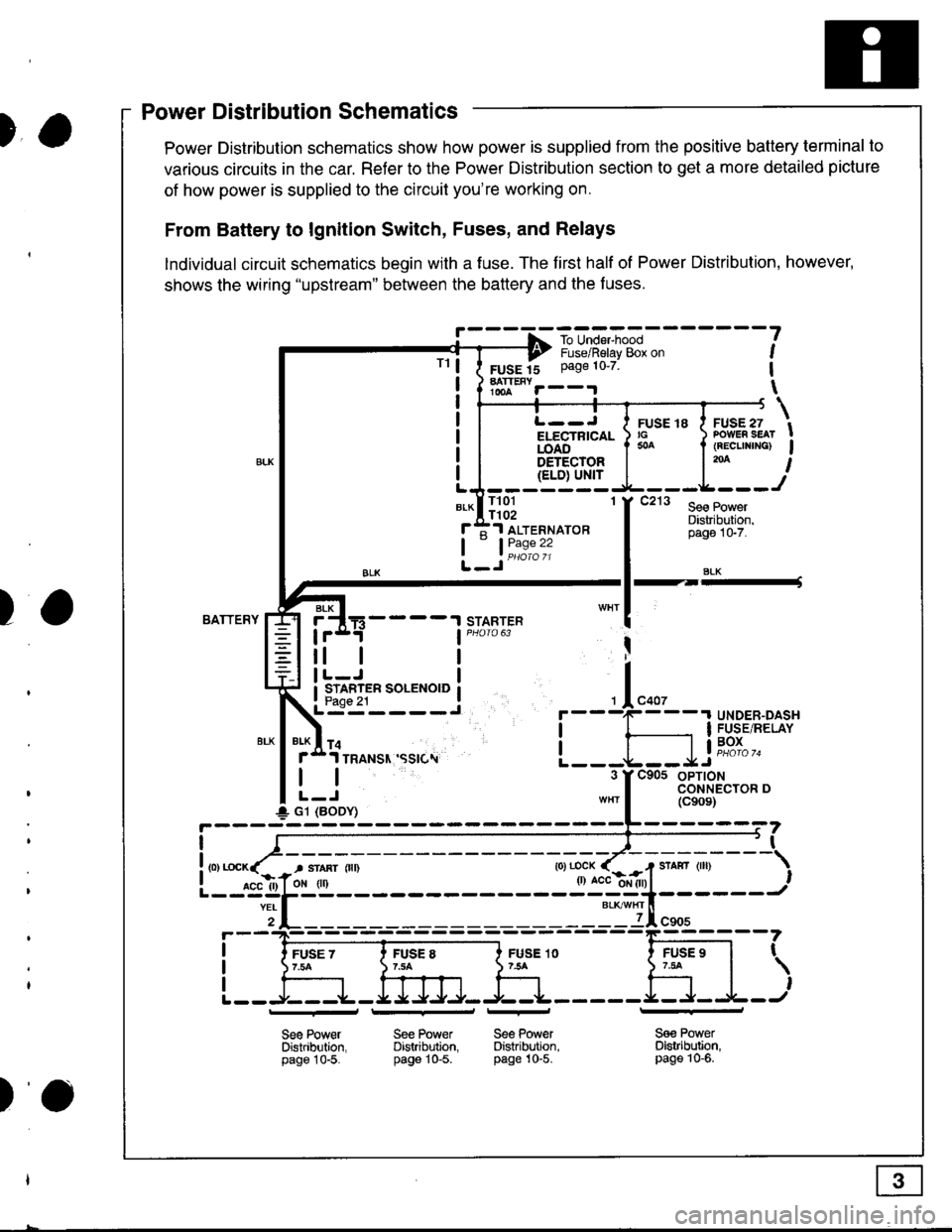
Power Distribution schematics show how power is supplied from the positive battery terminal to
various circuits in the car. Refer to the Power Distribution section to get a more detailed picture
of how power is supplied to the circuit you're working on.
From Battery to lgnition Switch, Fuses, and Relays
lndividual circuit schematics begin with a fuse. The first half of Power Distribution, however,
shows the wiring "upstream" between the battery and the f uses.
!' - - - -f -ro-unE,-"*l - - - - - - -
?---? i,"-")il"i"v-g& o" ,
FUSE 15 Page 10'7 1
hTt""r--.r \
TrL--J I ruse re I ruse zi/ ru:rE ro a .v-E., tELECTRTCAL ) rc ) PowER sEAr !iOA6".'-'- I * I (REcuNrNG) Igs-r-qqrg! | l'* I{ELD) Ul'{rLJ-------
*-lll3l 'f t"' l*.r:::f ;1 ALTERNAToR
tL_Jii1:"":
Distribuiion,pago 1G7.
SLK
BATTERYSTARTERBLK
4----t
tl
STARTER SOLENOID
I
I
+ G1 (BODY)
r
I
I
I
FUSE 1O754
Sge PowerDistribltion,page 10-5.
FUSE 97.tat
,
l---r+J
See Power Se€ PowerDistribution. Distribution.page 10-5. pag€ 10-5.
_l_
Sa€ PowerDistribution,page 10-6.
Power Distribution Schematics
tt
)o
Page 1387 of 1681
How To Use This Manual
Power Distribution Schematics
From Fuses to Relays and Components
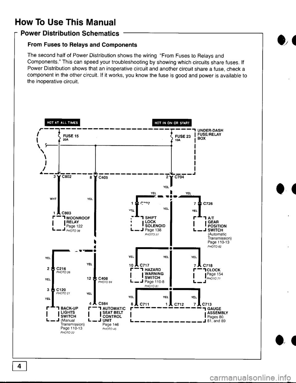
The second half of Power Distribution shows the wiring "From Fuses to Relays and
Components." This can speed your troubleshooting by showing which circuits share fuses. lf
Power Distribution shows that an inoperative circuit and another circuit share a fuse, check a
component in the other circuit. lf it works, you know the fuse is good and power is available to
the inooerative circuil.
ol
I
I
\
FUSE 15204
UNDER-OASHFUSE/RELAYBOXFUSE 2310A
\
I
/
O(
.II
l-- -
1?c-.7
.:r- I YEL
:*.l sHrFTr I LOCKI I SOLENOIDL- J Page 138PHOfO2T
I lFEt[,o'
L -J SWITCH(AutomaticTransmission)Page 110-13
-l PHaro 62
IYEL Iz I czrar -.lclocK
, l"i1:"':oL-Jc408
r-.l HAZARD
I t3'�S[t''i"L- J Page 110,8
:I-c564
1 AUTOMATIC
I SEAT BELTI CONTROLJ UNITPage 146
YEI
r
IL
c7t3
I l5"f,TE'"L -J (N,4anualTransmission)Page 110-13
r------
I ti:*'"T8*L____________J 81. and 89
3rc802 8
I
"* | YEL
I
', I "ro.f - 1 MooNRooF
| 13"'^TI",L-J,iiio'i'
2 3 C216
3 g cl20
ol
Page 1391 of 1681
How To Use This Manual
Symbols
Q,(Wire Color Abbreviations
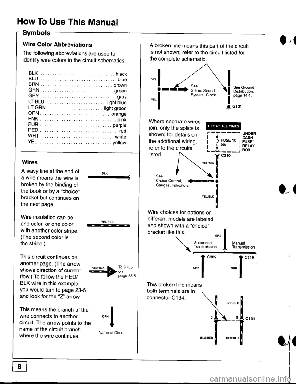
The following abbreviations are used to
identify wire colors in the circuit schematics:
BLK.... .........btack
BLU.... ......... btueBRN .... ........ brown
GRN.... ........ green
GRY .... ......... gray
LTBLU . ..... tighrbtue
LTGRN. ....ljghtgreen
ORN.... ....... orangePNK.... ..........pink
PUR .... ........ purpte
RED .... .......... redwHT... .,.......white
YEL .... ........ ye ow
A broken line means this part ot the circuit
is not shown; reler to the circuit listed for
the complete schematic.
",.I
ar
*.1
See GroundDistribution,page 14-1.
1G101
Where separate wires
join, only the splice is
shown; for details on
the additional wiring,
refer to the circuits
listed.i-l{:i
;["
UNDER.DASHFUSE/RELAYBOX
Wires
A wavy line at the end of
a wrre means the wire is
broken by the binding of
the book or by a "choice"
bracket but continues on
the next page.
Wire insulation can be
one color, or one color
with another color stripe.
(The second color is
the stripe.)
This circuit continues on
another page. (The arrow
shows direction of current
flow.) To follow the RED/
BLK wire in this example,
you would turn to page 23-5
and look for the "2" aftow.
This means the branch of the
wire connects to another
circuit. The arrow points to the
name of the circuit branch
where the wire continues.
BLK-Crulse Controt, QaalGauges, Indrcarors
!YEUBTK
II
Wire choices for options or
different models are labeled
and shown with a "choice"
This broken line means
both terminals are in
connector C134.
bracketlikethis
*J
Q,(
ManualTransmission
*'ffil:,*"1"' *"1""0
I
"""1
H
Name of Circuit
cl34
a,ll
Page 1400 of 1681
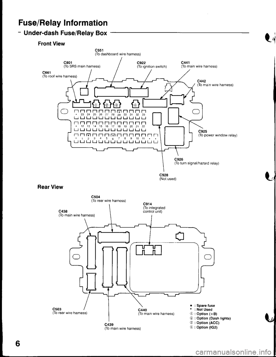
Fuse/Relay Information
- Under-dash Fuse/Relay Box
Front Viewt4
c55't(To dashboard wire harness)
c661(To root wire harness)
c801Oo SFIS main harness)c922(To ignition switch)
c440{To rrain wire harness)
c441(To main wire harness)
c442flo rra n wire harness)
c92sOo power window relay)
c928(Not used)
Rear View
c504(To rear wire harness)
c503. : Spare fuser : Not UsedO : Option (+B)
O : Option (Dash lights)O : Option (ACC)
O : Option (lG2)c439(To main wire harness)
6
-) n Fl r"r r'r rl r-l r-r ri r'1 Tl rl r-1. 23 24 25 26 27 2a 29 30 31 32 33t_-.1 u u ! tJ LJ Ll t. Ll tJ l. tJ
- r-l n T'l T-l r't T-1 T-t r-l T-t r-l r'1.12 13 14 15 16 17 18 19 2A 21 22LI tJ LJ LI tJ I.J t-J tJ IJ IJ IJ I.J
r-r Tl l;t T'l T-l T'1 rn r-l T-t r'l T1 Tl r'1 n. 1 2 3 4 5 6 7 I 9 10 11 . .t-l LJ LJ LJ LJ [J t-t LJ Ll LJ t_l t-J Lr u
(To rear wire harness)
Page 1401 of 1681
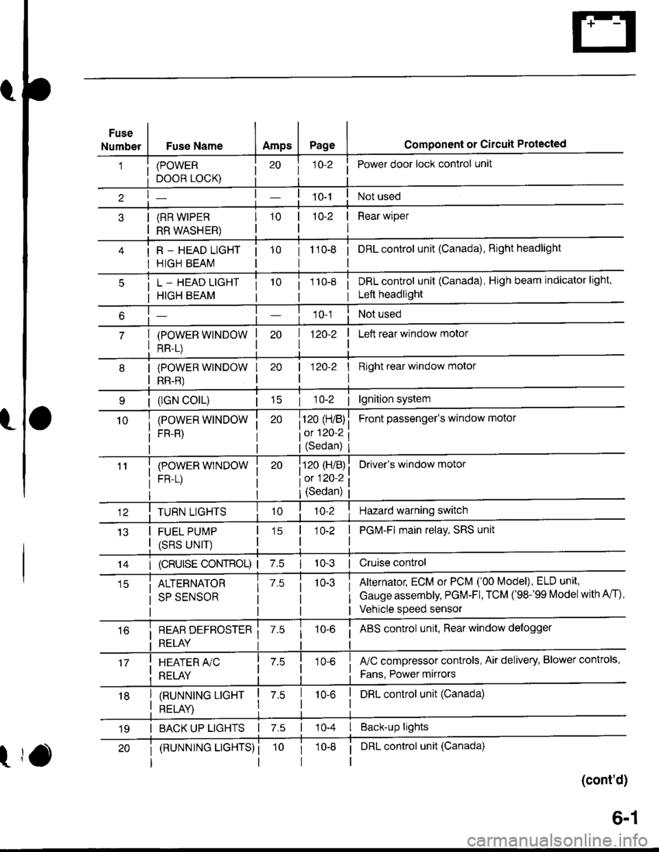
Fuse
NumberFuse NameAmpsPagecomponent or circuit Protected
(POWER
DOOR LOCK)
(RR WIPER
RR WASHER)
R _ HEAD LIGHT
HIGH BEAM
j 1o-2Power door lock control unit
10-2 | Rear wiper
I
tto-e i onLcontrol unit (Canada), Right headlight
L _ HEAD LIGHT
HIGH BEAM
(POWER WINDOW
RR-L)
i 1 10-8i DRL control unit (Canada), High beam indicator light,
i Left headlight
1 0-1Not used
| 1zo-z
I
I Left rear window motor
| (lGN colL)| 15
(POWER WINDOW
FR-R)
(POWEB WINDOW
FR-L)
I Right rear window molor
I
Front passenger's window motol
Driver's window motor
| 120-2
i120 (H/B)
iot 120-2
l(Sedan)
i120 (H/B)
l0:120 ?
IJ13
TURN LIGHTS
FUEL PUMP
(SRS UNIT)
(Sedan)
'lo-2Hazard warning switch
1O-2 | PGM-FI main relay, SRS unit
I
14I (cRUlsE coNTRoL) | 7.510-3 | Cruise control
ALTERNATOR
SP SENSOR
7.510-3Alternator, ECM or PCM ('00 Model), ELD unit,
Gauge assembly, PGM-Fl, TCM ('98-'99 Modelwith A/f),
Vehicle speed sensor
i REAR DEFBOSTER ii RELAY i
10-6i ABS control unit, Rear window defogger
I HEATER A/C
: RELAY
fuC compressor controls, Air delivery, Blower controls,
Fans. Power mirrors
I tnururutruc ucxr I z.s
I otrt av I
I DRL control unit (Canada)10-6
I BACK UP LIGHTS | 7.s | 10-4 I Back-up lights
t
(RUNNTNG LTGHTS) ii DRL control unit (Canada)
(cont'd)
19
6-1