gearbox HONDA INTEGRA 1998 4.G Workshop Manual
[x] Cancel search | Manufacturer: HONDA, Model Year: 1998, Model line: INTEGRA, Model: HONDA INTEGRA 1998 4.GPages: 1681, PDF Size: 54.22 MB
Page 36 of 1681
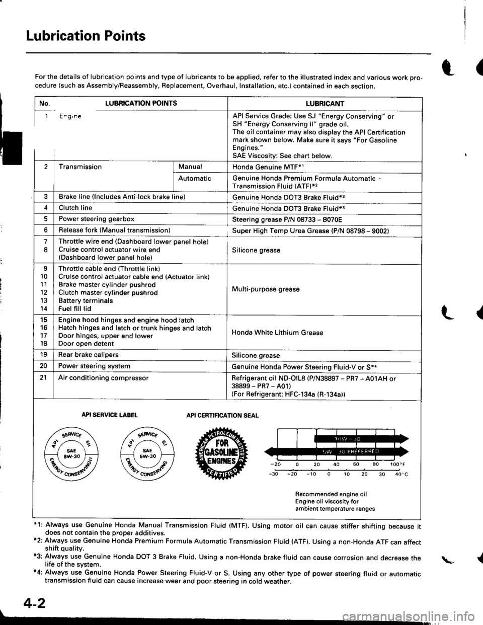
Lubrication Points
No. LUBRICAnON POINTSLUBRICANT
1 E^g,neAPI Service Grade: Use SJ "Energy Conserving" orSH "Energy Conserving ll" grade oil,The oil container may also display the API Certificationmark shown below. Make sure it savs "For GasolineEngines. "
SAE Viscositv: See chart below.
2TransmissionManualHonda Genuine MTF*1
AutomaticGenuine Honda Premium Formula AutomaticTransmission Fluid (ATF)*,
Brake line (lncludes Anti-lock brake line)Genuine Honda DOT3 Brake Fluid13
Clutch lineGenuine Honda DOT3 Brake Fluid*3
Power steering gearboxSteering grease P/N 08733 - 8070E
Release fork lManual transmission)Sup€r High Temp Urea Grease (P/N 08798 - 9002)
1
8
Throttle wire end (Dashboard lower oanel hole)Cruise control actuator wire end(Dashboard lower Danel hole)Silicone grease
o
10
11
14
Throttle cable end (Throttle link)Cruise control actuator cable end (Actuator link)Brake master cvlinder oushrodClutch master cylinder pushrod
Battery terminals
Fuel fill lid
Multi-purpose grease
to
17
18
Engin6 hood hinges and engine hood latchHatch hinges 8od latch or trunk hinges and latchDoor hjnges, upper and lowerDoor ooen detent
Honda White Lithium Grease
19Rear b.ake calipersSilicone grease
20Power steering systemGenuine Honda Power Steering Fluid-V or S*.
21Ai|' conditioning compressorRefrigerant oii ND-O|L8 {P/N38897 - PR7 - A01AH or38899-PR7-A01)(For Refrigerant: HFC-134a (R- 134a))
API SERVICE LABELAPI CERTIFICATION SEAL
Recommended engine oilEngin€ oil viscosity lorambrent lemperature ranges
r(For the details of lubrication points and type of lubricants to be applied, refer to the illustrated index and various work Dro-cedure (such as Assembly/Reassembly, Replacement, Overhaul, Installation. etc.) contained in each section,
*1: Always use Genuine Honda Manual Transmission Fluid (MTF). Using motor oil can cause stiffer shifting because itdoes not contain the proper addtuves.*2: Always use Genuine Honda Premium Formula Automatic Transmission Fluid (ATF). Using a non-Honda ATF can affectshift quality.*3: Always use Genuine Honda DOT 3 B.ake Fluid, Using a non-Honda brake fluid can cause corrosion and decrease thelife of the system.'4: Always use Genuine Honda Power Steering Fluid-V or S. Using any other type of power steering fluid or automatictransmission fluid can cause increase v,/ear and poor steering in cold weather.
L(
{
4-2
Page 652 of 1681
I
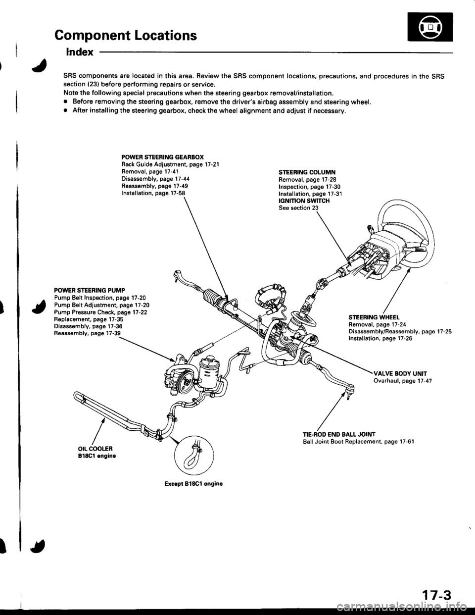
Component Locations
Index
SRS components are located in this area. Review the SRS component locations, precautions, and procedures in the SRSsection (23) before performing repairs or service.
Note the following special precautions when the steering gearbox removal/installation,
. Before removing the steering gearbox, remove the driver's airbag assembly and steering wheel.
. After installing the steering gearbox, ch6ck the wheel alignmentand adjust if necessary.
POWER STEERING GEARBOXRack Guid€ Adjustment, page 17 -21
Removal, pago 17-4'1Disassembly, page 17-44Reassombly. page'17-49Installation, page 17-58
STEEBING COLUMNRemoval. page 17-28Inspection, pago 17-30Installation, page 17-3'1|GNMON SWITCHSee section 23
POWER STEERING PUMPPump Belt Inspection. page 17-20Pump Belt Adjustment, page 17 -20
Pump Pr€ssuro Check, page 17'22Roplacament, page 17-35Dis686embly, page 17-36Reassembly, page 17-39
STEEBING WHEELRomoval, page 17-24Disassembf y/Reassembly, paga 17 -25
Installation, page 17-26
TIE.BOD END BALL JOINTBallJoint Boot Replacement, page 17-61
Exc.pt BlSCl onginc
17-3
Page 653 of 1681
System Description
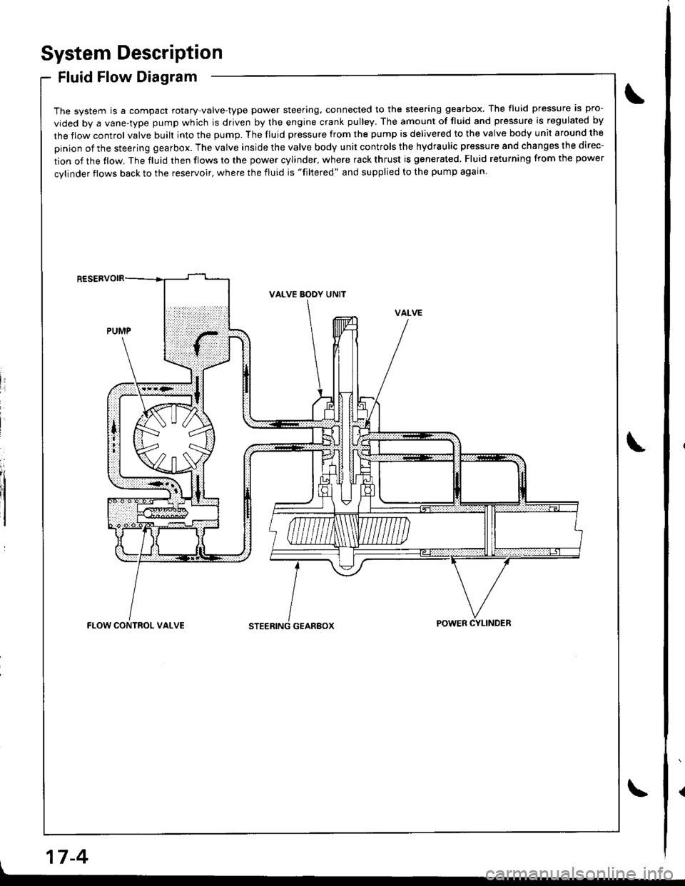
Fluid Flow Diagram
The system is a compact rotary-valve-type power steering, connected to the steering gearbox. The fluid pressure is pro-
vided by a vane-type pump which is driven by the engine crank pulley. The amount of fluid and pressure is regulated by
the flow control valve built into the pump. The fluid pressure from the pump is delivered to the valve body unit around the
pinion of the steering gearbox. The valve inside the valve body unit controls the hydraulic pressure and changes the direc-
tion of the tlow. The fluid then flows to the power cylinder, where rack thrust is generated. Fluid returning from the power
cylinder flows back to the reservoir, where the fluid is "filtered" and supplied to the pump again
li
I
VALVE BODY UNIT
GEARBOXFLOW CONTROL VALVEPOWER CYLINDER
17-4
Page 655 of 1681
System Description
Steering Pump (cont'd) .
17-6
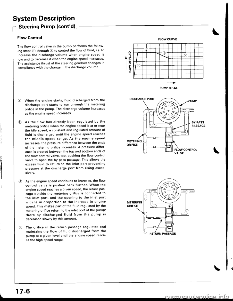
Flow Control
The flow control valve in the pump performs the follow-
ing steps O through aE ro control the flow of fluid, i.e. to
increase the discharge volume when engine speed is
low and to decrease it when the engine speed increases
The assistance thrust of the steering gearbox changes in
compliance with the change in the discharge volume.
When the engine starts, fluid discharged from the
discharge port starts to run through the metering
ori{ice in the pump. The discharge volume increases
as the engine speed increases.
As the flow has already been regulated by the
metering orifice when the engine speed ls at or near
the idle speed, a constant and regulated amount of
fluid is discharged until the engine speed reaches
the middle speed range. As the engrne speed
increases, the pressure difference between the ends
of the metering orifice increases. A pressure differ-
ence is created between the top and bottom ends of
the flow control valve, too, pushing the flow control
valve to open the by-pass passage. This allows the
excess fluid to return to the inlet port preventing
pressure at the discharge port trom rising exces-
As the engine speed continues to increase, the flow
control valve is pushed back further' When the
engine speed reaches a given speed, the return pas
sage outside the melering orifice is connected to
the inlet port, and the opening to the inlet port
widens in prooortion to the increase in engine
speed. This makes part of the fluid regulated by the
metering orifice return to the inlet port of the pump;
there by discharged Iluid lrom the pump rs
decreased slowlv by this amount
The orifice in the return passage regulates and
maintains the flow of fluid discharged from the
pump at a given level untilthe engine speed reach-
es the high speed range.
o
fd
lot3rotr
FLOW CURVE
PUMP R,P.M,
o-l
a,
II
,a\
METERINGORIFICE
an
Page 657 of 1681
System DescriPtion
Steering Gearbox
it
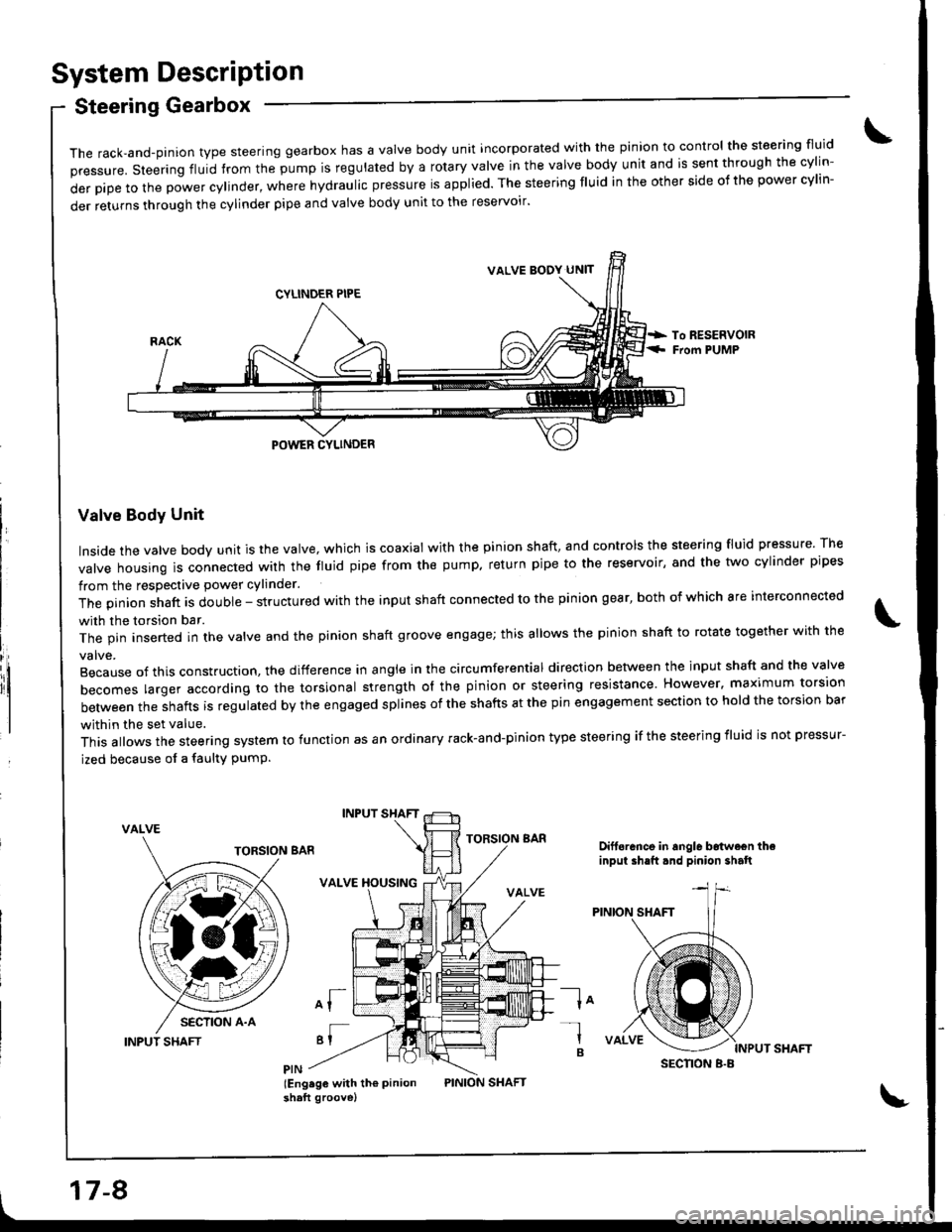
The rack,and-pinion type steering gearbox has a Valve body unit incorporated with the pinion to control the steering fluid
pressure. steering fluid from the pump is regulated by a rotary valve in the valve body unit and is sent through the cylin-
derpipetothepowercy|inder,wherehydrauIicpressureisapp|ied.Thesteeringf|Uidintheothersideofthepowercy|in-
der returns through the cylinder pipe and valve body unit to the reservoir'
Valve Body Unit
Inside the valve body unit is the valve, which is coaxial with the pinion shaft, and controls the steering fluid pressure The
valve housing ls connected wirh the fluid pipe from the pump. return pipe to the reservoir, and the two cylinder pipes
from the respective power cylinder.
The pinion shaft is double - structured with the input shaft connected to the pinion gear, both of which are interconnected
with the torsion bar.
The pin inserted in the valve and the pinion shaft groove engage; this allows the pinion shaft to rotate together with the
Because of this construction. the difference in angle in the circumferential direction between the input shaft and the valve
becomes larger according ro the torsional strength ol the pinion or steering resistance. However. maximum torsion
between the shafts is regulated by the engaged splines of the shafts at the pin engagement section to hold the torsion bar
within the set value.
This allows the steering system to function as an ordinary rack-and-pinion type steering if the steering iluid is not pressur-
ized because of a faulty PumP.
VALVE
INPUT SHAFT
INPUT SHAFT
VALVE XOUSING
of
'I
lEng.ge with th€ Pinionshaft groove)
TORSION BARDift6rance in angle b6twe€n theinput ih.ft.nd pinion shalt
la-l
B
VALVE BODY UN]T
SECNON B.B
17-8
Page 659 of 1681
Troubleshooting
General Troubleshooting
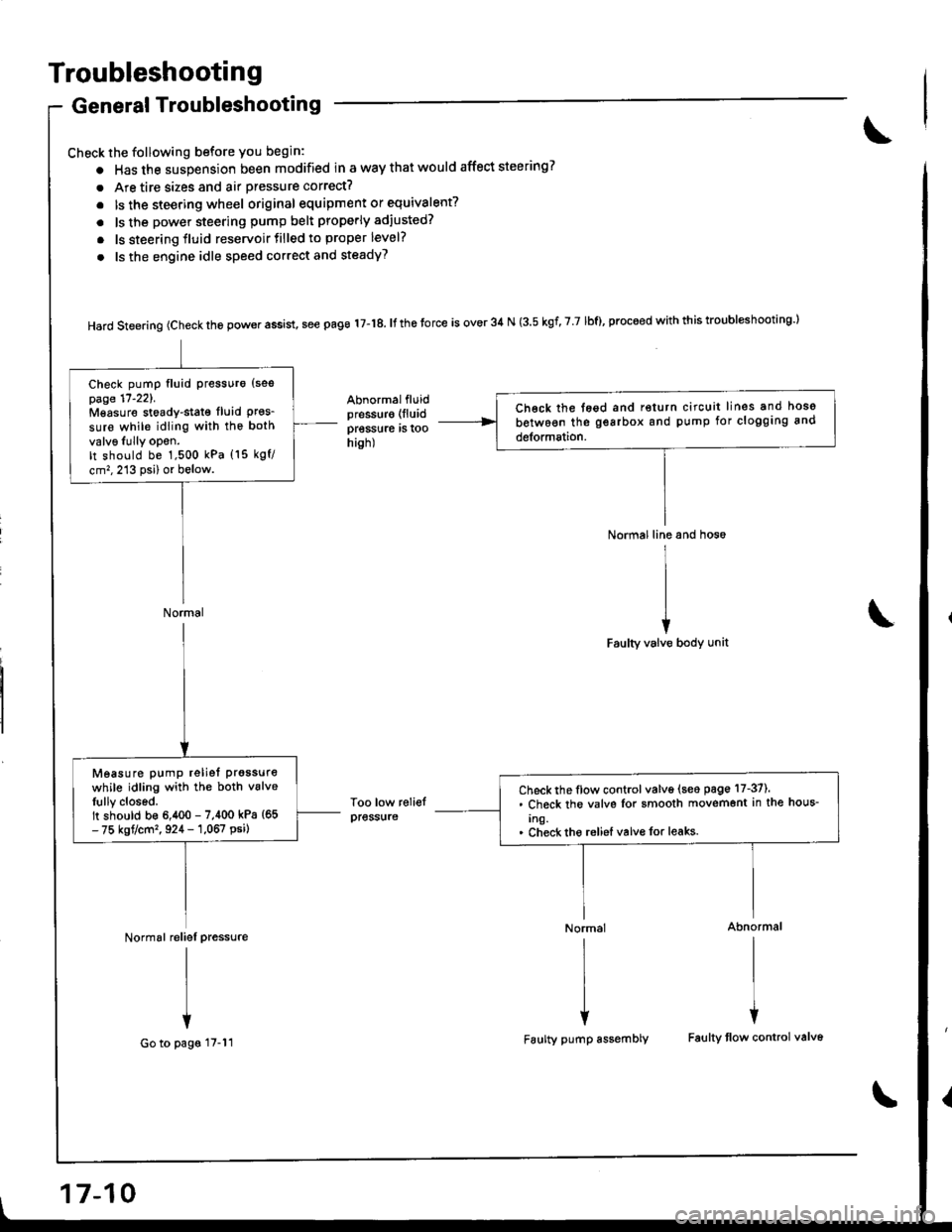
Check the following before you begin:
o Has the suspension been modified in a way that would affect steering?
. Are tire sizes and air pressure correct?
. lsthe steering wheel original equipment or equivalent?
. ls the power steering pump belt properly adiusted?
. ls steering fluid reservoirtilled to proper level?
. ls the engine idle speed correct and steadyT
Hard steering (check the power assist, see page 17-18. It the torce is over 34 N (3.5 kgf, 7 7 lbf), proceed with this troubl*hooting l
Abnormalfluidpressur€ (lluid
pressure rs roohish)
Too low reliefpress{ire
Normal line and hos6
I
II
iFaulty valve body unit
Normal Abnormal
rlrl
l{
Faulty pump assembly Faulty tlow control valv6
Ch€ck the tegd and return circuit lines and hoso
between the gearbox and pump for clogging and
detormation.
Check pump fluid Pressuro {sespage 17'221.Mgasure stoady-stat€ fluid Pres_sure while idling with the both
valv6Iully opon.It should be 1,500 kPa (15 kgf/
cm,,213 psi) or below.
Normal
Check the flow control valve (seo page 17-37).. Check the valvs Ior smooth movemont in the hous-
Ing.. Check tho reliel valvo for leaks.
Measure pump reliet prgssure
while idling with the both vslveIully closed.It should b€ 6,400 - 7,400 kPa {65- 75 kgt/cm'�, 924 - 1,067 psi)
Normal reliel pressure
I
I
+
Go to pags 17-11
17-10
Page 660 of 1681
From page 17-10
Normal
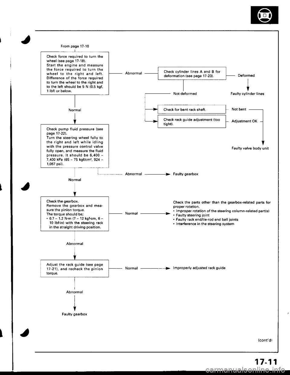
Check lorce required to turn thewhool (see page 17-'18).Start the engine and measu16the force required to turn thewheel to the right and left.Difference of the force requiredto twn the wheel to the right andto the left should be 5 N (0.5 kgf,1 lbl) or below.
Deformed
I
iFaulty cylinder lines
Not bent
Adjustment OK
Faulty valve body unit
Abnormal --> Faulty gearbox
Ch€ck th6 pans other than the gearbox-related parts lorDrooer rolaton.
. . lmproper rotation ofthe steering column-related pan{s}----------------- . tau[y $eenng lornt. Faulty rack endtio-rod ond balljoints. Intgrferonce in the steering system
Normal -----> lmproperly adjusted rack guide
Check lor bent rack shaft.
Check pump fluid pressure (seepage 17-22).Turn the steoring wheel fully tothe right and l€ft while idlingwilh the pressure control valveIully open, and measure the Iluidpressure. lt should be 6,400 -
7,400 kPa (65 - 75 kgflcmr, 924 -
1,067 psi).
Normal
Ch€ck the gearbox.Remove the gearbox and mea-sure the pinion torque.The lorque should be;. 0.7 - '1.2 N.m (7 - 12 kgf.cm, 6 -
10 lbf.in) wjth the steering rackin the straight driving position.
Abnormal
Adjust the rack guide {see page17-211, and recheck the pinion
torque.
17-11
Page 661 of 1681
Troubleshooting
General Troubleshooting (cont'dl
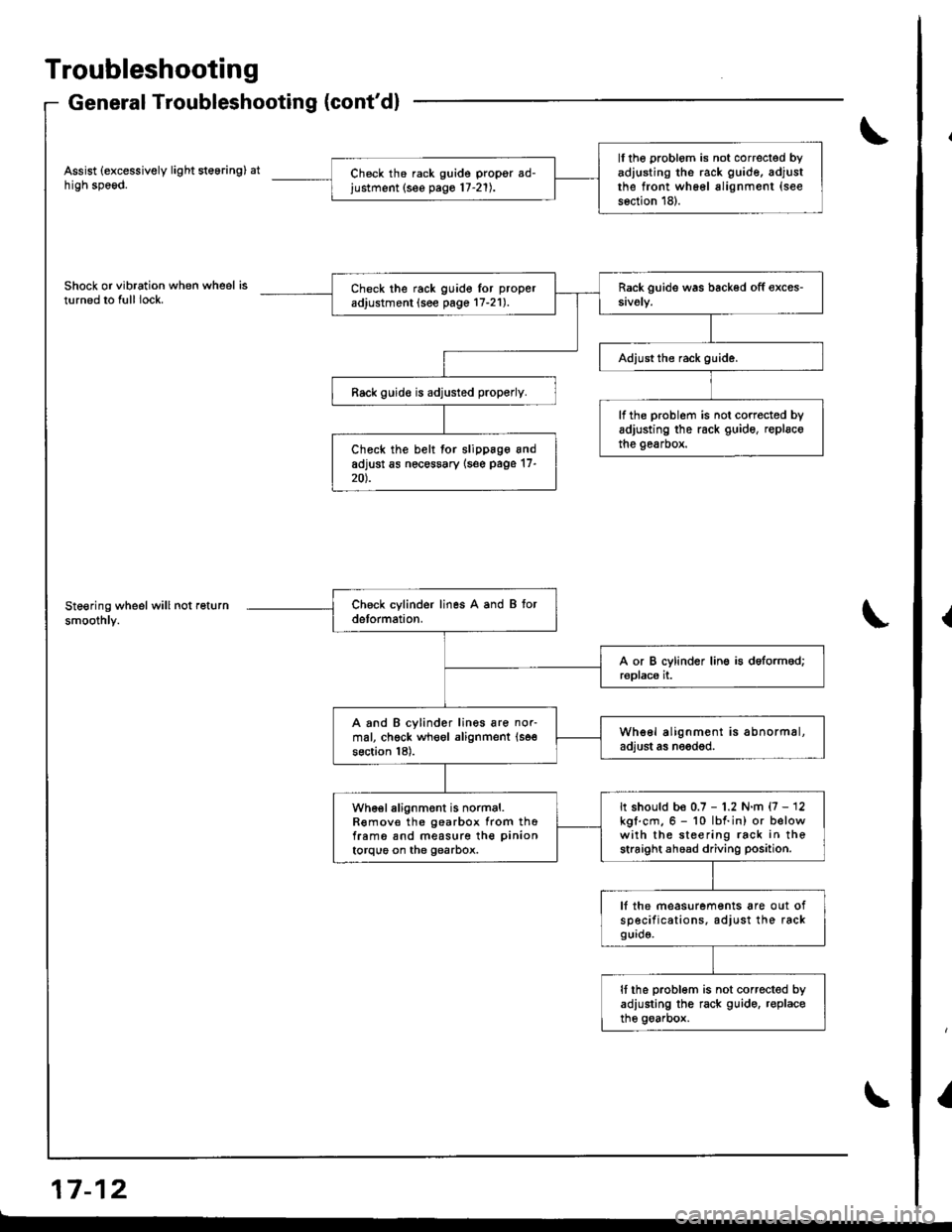
Assist (excessively light steering) athigh speod.
Shock or vibration when wheel isturned to full lock.
Steering wheel will not return
smoothly.
a-, aa GrI r- tz
ll the problom is not correcled byadiusting the rack guide, adjustthe front wh66l alignment (see
s6ction 18).
Ch6ck th6 rack guide propgr ad-justment (see pago 17-21).
Check the rack guido lor proper
adjustment (see page 17-21).
Rack guid€ is adjusted properly.
lf the problem is not corrected byadjusting the rack guide, replscothe gearbox.Check the belt for slippage andadjust as nec€ssary {s6e page 17-20).
A and B cylinder lines are nor-mal, chgck wheol alignment (se€
section 18).
Whe6l alignment is abnormal,adjust as needod.
It should be 0.7 - 1.2 N.m {7 - 12kgl.cm.6 - 10 lbf.in) or belowwith the steering rack in thestraight ahoad driving position.
wh€el alignment is normal.R€mov€ the gearbox from thofram6 snd measure the pinion
torque on the gearbox.
lf the measurements are out ofsp€cifications. adjust the rackgurd9.
It the problom is not corrected byadiusting the rack guido. r€placethe goarbox.
{
I
Page 665 of 1681
Troubleshooting
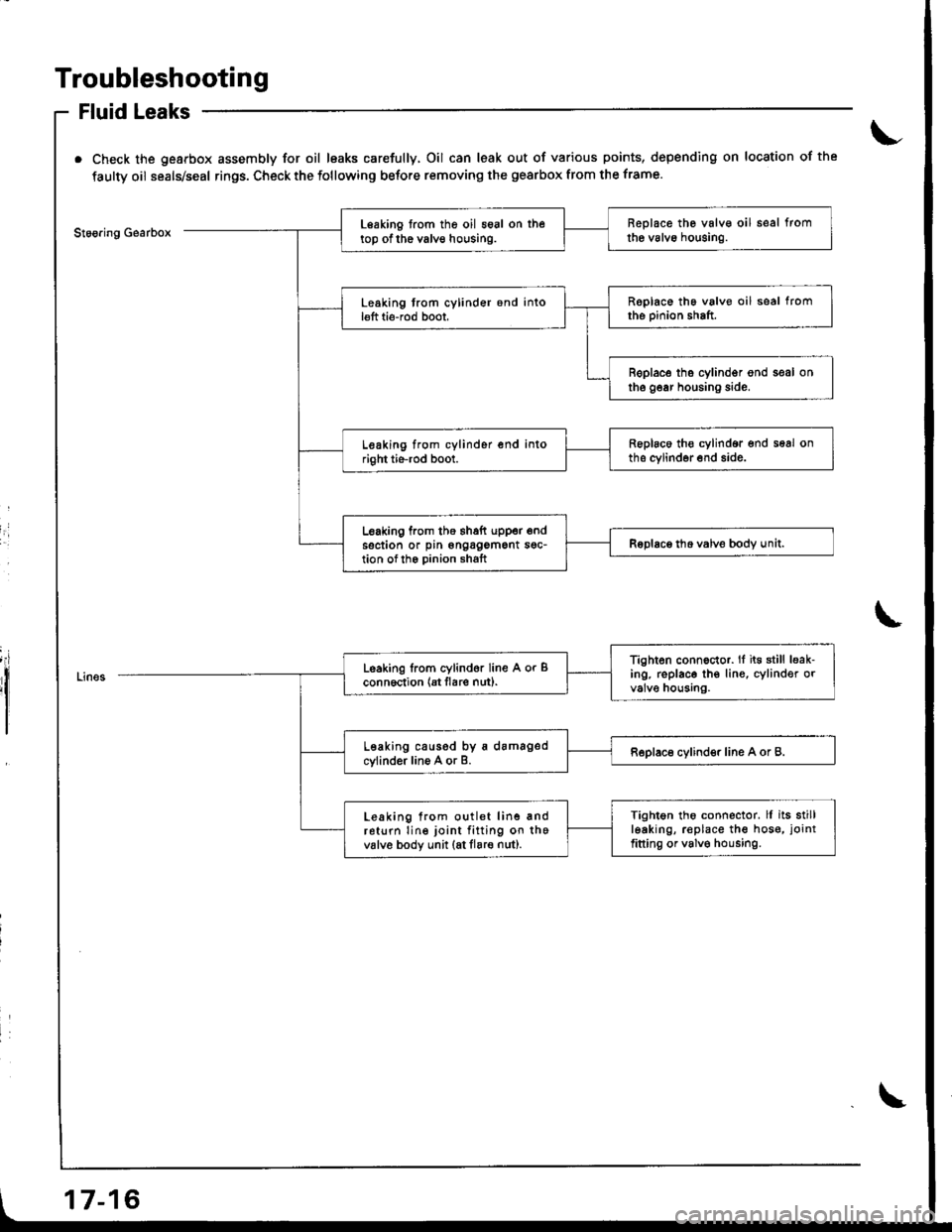
Fluid Leaks
Check the gearbox assembly for oil leaks carefully, Oil can leak out of various points, depending on location of the
faulty oil seals/seal rings. Check the following before removing the gearbox from the frame.
Stoo.ing GearboxReplace the valv€ oil seal fromthe valvo houging.Leaking from the oil seal on thetop of the valve housing.
Roplace the valve oil seal fromthe pinion shaft.Leaking trom cylinder 6nd intol€ft ti6-rod boot,
B€place tho cylindgr ond seal onthe gear housing side.
Replaco th€ cylindor end seal onths cylinder end side.Leaking from cylinder end intoright tie-rod boot.
Leaking from the thaft upper endsection or pin ongagement sgc-tion ofth6 Dinion shaftRoDlace tho valve bodv unit.I
I
Tighten connector. lf it€ still leak-ing. replace th€ lin€, cylinder orvalve housing.
Leaking lrom cylind6r line A or Bconn6ction {Et flare nut).
Leaking caused by a damagedcylinder line A or B.Replace cylinder line A or B.
Tightgn tho connector. ll its stillleaking, r€place the hos€, joint
fitting or valv€ housing.
Leaking from outlet line andreturn line joint fitting on thevalv6 body unit (at flare nut).
17-16
Page 667 of 1681
Inspection and Adjustment
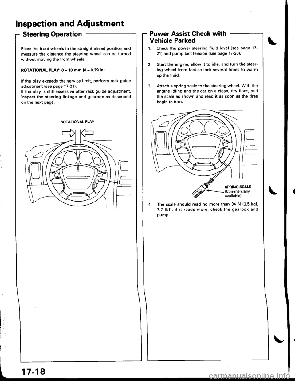
Steering Operation
Place the front wheels in the straight ahead position and
measure the distance the steering wheel can be turned
without moving the front wheels.
ROTATIONAL PLAY: 0 - 10 mm {0 - 0.39 inl
lf the play exceeds the service limit. perform rack guide
adiustment (see page 17-211.
lf the play is still excessive after rack guide adjustment.
inspect the steering linkage and gearbox as described
on the neld page.
Power Assist Check with
Vehicle Parked
Check the power steering fluid level (see page 17-
21) and pump belt tension (see page 17-201.
Start the engine, allow it to idle. and turn the steer
ing wheel from lock-to-lock several times to warm
up the fluid.
Attach a spring scale to the steering wheel. With the
engine idling and the car on a clean. dry floor. pull
the scale as shown and read it as soon as the tires
begin to turn,
4. The scale should read no more than 34 N (3.5 kgf,
7.7 lbf). lf it reads more, check the gearbox and
pump.
ROTATIONAL PLAY