check engine light HONDA INTEGRA 1998 4.G Owner's Manual
[x] Cancel search | Manufacturer: HONDA, Model Year: 1998, Model line: INTEGRA, Model: HONDA INTEGRA 1998 4.GPages: 1681, PDF Size: 54.22 MB
Page 757 of 1681
a
BrakePedal
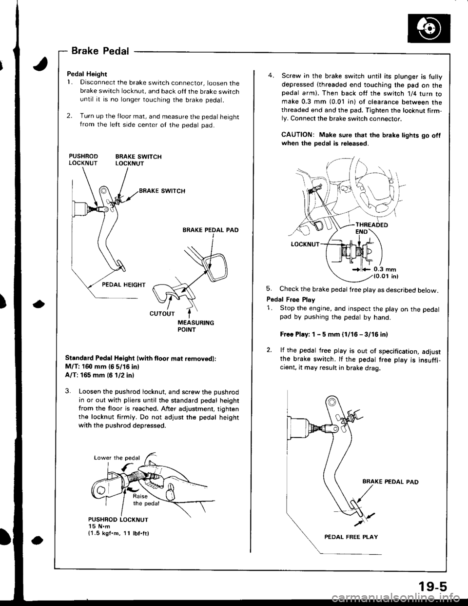
Pedal Height
1. Disconnect the brake switch connector, loosen thebrake switch locknut, and back oll the brake switchuntil it is no longer touching the brake pedal.
2. Turn up the jloor mat, and measure the pedal heightfrom the lett srde center of the pedal pad.
PUSHROD ERAKE SWITCHLOCKNUT LOCKNUT
swtTcH
BRAKE PEOAL PAOI
MEASURINGPOINT
Standard Pedal Hsight (wiih ftoor m8t removedl:
M/T: 160 mm {6 5/16 in}
A/T: 165 mm (6 1/2 in)
3. Loosen the pushrod locknut, and screw the pushrod
in or out with pliers until the standard pedal height
from the floor is reached. After adjustment, tighten
the locknut firmly. Do not adjust the pedal height
with the pushrod depressed.
{1.5 kgf.m, 11 lbt.ftl
19-5
Screw in the brake switch until its plunger is fully
depressed (threaded end touching the pad on thepedal arm). Then back off the switch 1/4 turn tomake 0.3 mm (0.01 in) of clearance between thethreaded end and the pad. Tighten the locknut firm-ly. Connect the brake switch connector.
CAUTION: Make sure that the brake lights go oflwhen the pedal is released.
5. Check the brake pedal free play as described below.
Pedal Free Play
1. Stop the engine, and inspect the play on the pedal
pad by pushing the pedal by hand.
Free Play: 1 - 5 mm {l/16 - 3/16 in)
2. lf the pedal free play is out of specification, adjustthe brake switch. tf the pedal free play is insuffi_cient, it may result in brake drag.
PEDAL PAD
Page 758 of 1681
Inspection and Adiustment
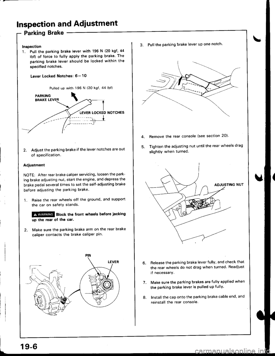
Parking Brake
Inspection
1. Pull the parking btake lever with 196 N
lbf) of force to Jully apply the parking
parking brake lever should be locked
soecified notches.
Lever Locked Notches: 6- l0
{20 kgf, 44
brake. The
within the
Pulled up with 196 N {2O kgf, 44 lbf)
LEVER LOCKED NOTCHES
2, Adjust the parking brake if the lever notches are out
of specification.
Adjustment
NOTE: After rear brake caliper servicing.loosen the park-
ing brake adjusting nut, start the engine, and depress the
brake pedal several times to set the self-adjusting brake
before adiusting the parking brake
1. Raise the rear wheels oIt the ground. and suppon
the car on safety stands.
!!@ ato"t the trort whoels bsfore jacking
up the roal ot tha car'
2. Make sure the parking brake arm on the rear brake
caliDer contacts the brake caliper pin.
19-6
8.
3. Pullthe parking brake lever up one notch'
Remove the rear console {see section 20)'
Tighten the adjusting nut until the rear wheels drag
slightly when turned.
7.
Release the parking brake lever fully, and check that
the rear wheels do not drag when turned. Readjust
if necessary.
Make sure the parking brakes are fully spplied when
the parking brake lever is pulled up fully.
Install the cap onto the parking brake cable end, and
reinstall the rear console.
Page 767 of 1681
1.
8.
NOTE: lf the clearance between the gauge body
and adjusting nut is 0.4 mm (0.02 in), the pushrod-
to-piston clearance is 0 mm. However, if the clear-
ance between the gauge body and adjusting nut is
0 mm, the pushrod-to-piston clearance is 0.4 mm(0.02 in) or more. Therefore it must be adjusted and
rechecked.
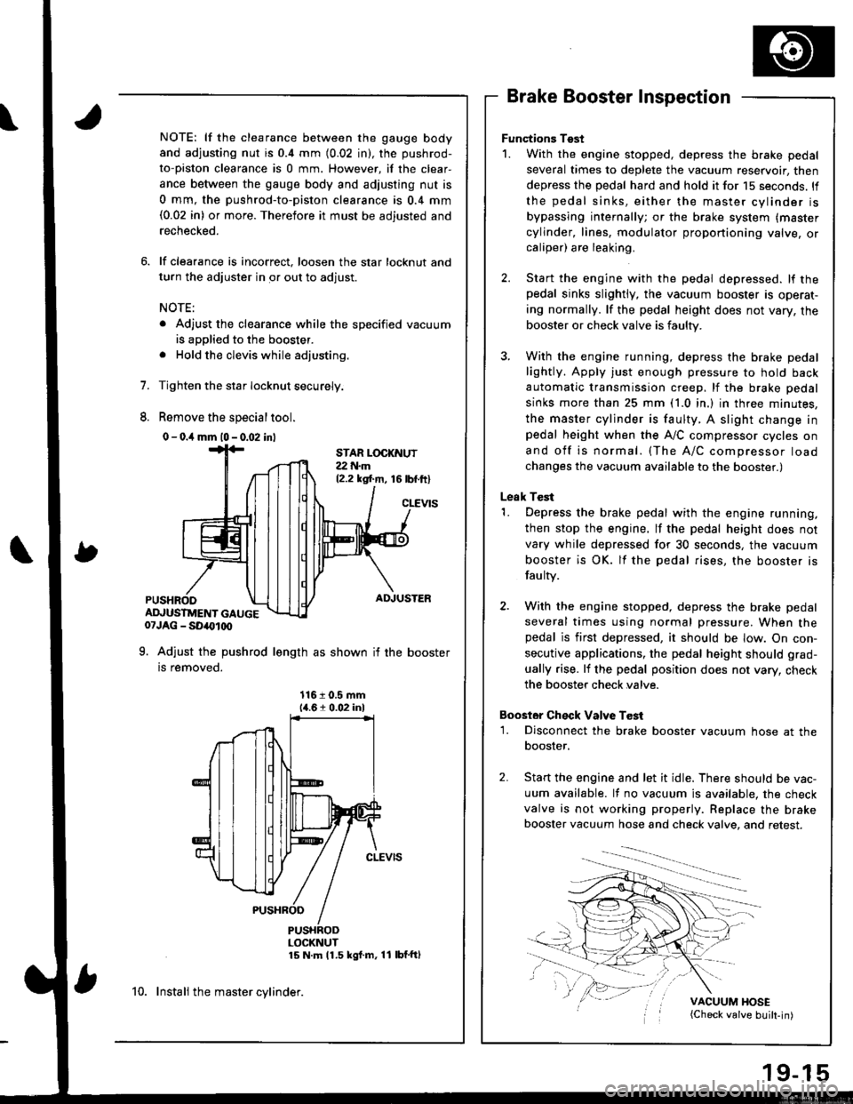
lf clearance is incorrect, loosen the star locknut and
turn the adjuster in or out to adjust.
NOTE:
. Adjust the clearance while the specified vacuum
is applied to the booster.
. Hold the clevis while adjusting.
Tighten the star Iocknut securely.
Remove the special tool.
0 - o.il mm l0 - 0.02 inl
Brake Booster Inspection
Functions Tgst
1. With the engine stopped, depress the brake pedal
several times to deplete the vacuum reservoir, then
depress the pedal hard and hold it for 15 seconds. ll
the pedal sinks, either the master cylinder is
bypassing internally; or the brake system (master
cylinder, lines, modulator proportioning valve, orcaliper) are leaking.
Start the engine with the pedal depressed. lf thepedal sinks slightly, the vacuum booster is operat-
ing normally. lf the pedal height does not vary, the
booster or check valve is faulty.
With the engine running, depress the brake pedal
lightly. Apply just enough pressure to hold back
automatic transmission creep, lf the brake pedal
sinks more than 25 mm (1.0 in.) in three minutes,
the master cylinder is faulty. A slight change inpedal height when the A,,/C compressor cycles on
and off is normal. (The A/C compressor load
changes the vacuum available to the booster.)
Leak Test
1. Depress the brake pedal with the engine running,
then stop the engine. lf the pedal height does not
vary while depressed for 30 seconds, the vacuum
booster is OK. lf the pedal rises, the booster is
fau lty.
2. With the engine stopped, depress the brake pedal
several times using normal pressure. When thepedal is first depressed, it should be low. On con-
secutive applications, the pedal height should grad-
ually rise. lf the pedal position does not vary, check
the booster check valve.
Boostor Ch€ck Valve T6st
1. Disconnect the brake booster vacuum hose at the
booster,
Start the engine and let it idle. There should be vac-
uum available. It no vacuum is available. the check
valve is not working properly. Replace the brake
booster vacuum hose and check valve, and retest.
VACUUM HOSE(Check valve built-in)
STAR LOCKNUT22 t{.m12.2 ksl.m, 16lbf.ftl
cLEVtS
ADJUSTER
ADJUSTMENT GAUGE07JAG - SD40t00
9. Adjust the pushrod length as shown if the booster
is removed.
1161 0.5 mm14.61 0.02 inl
PUSHRODLOCKNUT15 N m 11.5 kgf m, 11 lbf'ftl
10. Instali the master cylinder.
Page 794 of 1681
Troubleshooting
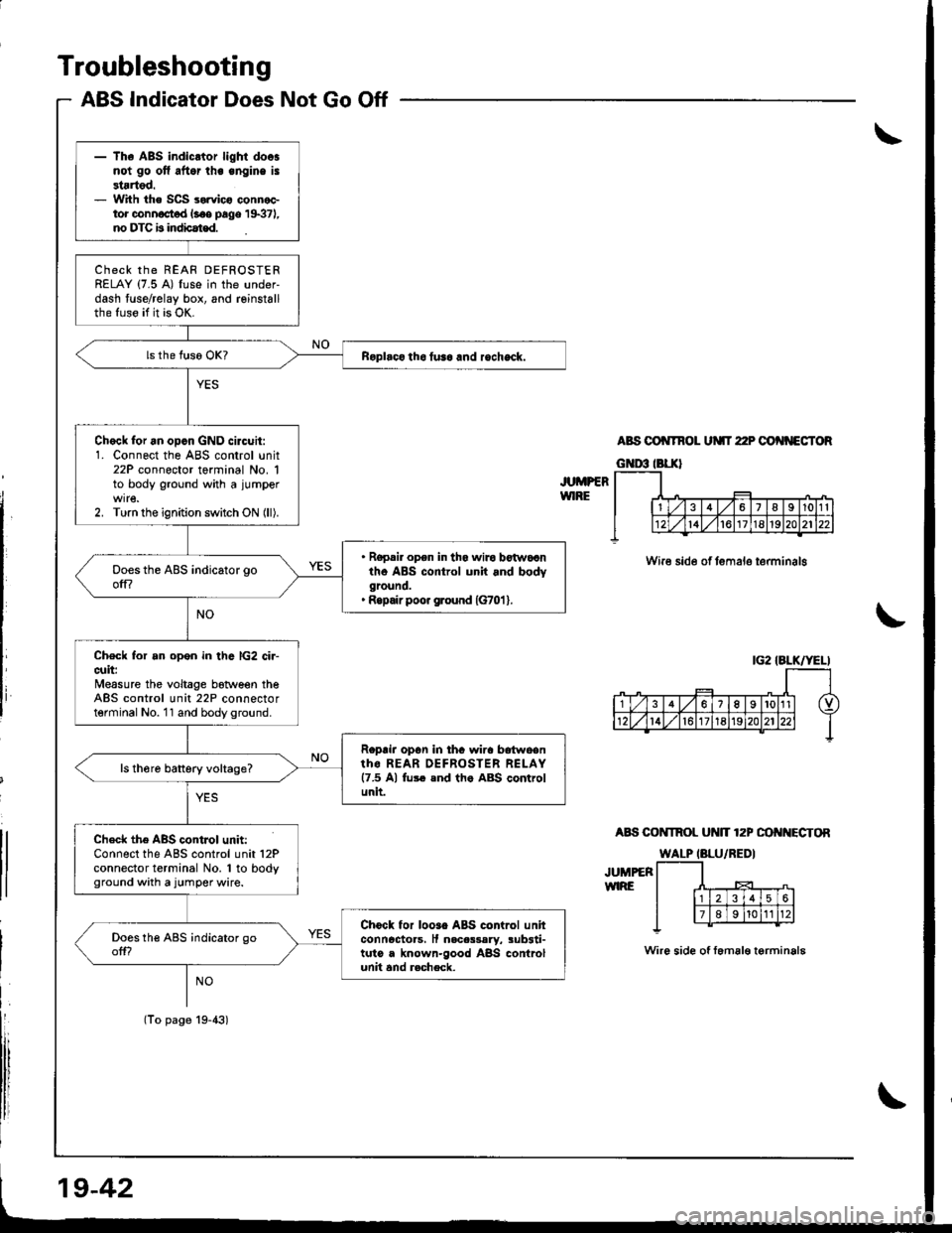
ABS Indicator Does Not Go Off
JUMPERWIRE
ABS OO TNOL UMT 22P OO'{NECTOR
Wire side of temalo terminalg
A8S COI{TROL Ut{lT 12P OO I{ECTOR
JUMPEFWIRE
Wire side of femal€ terminala
|G2 IALK/YELI
- The ABS indicltor light doosnot go ofl aftor lhe engine is3tartod.- With the SCS sorvico connoctor connoct d l.oe page 19371,no DTC b indbat€d.
ChECK thE REAF DEFROSTERRELAY (7.5 A) fuse in the under-dash fuse/relay box, and reinstallthe fuso if it is OK.
Roplaco tho tusa and rocheck.
Chock for an opcn GND circuit:1. Connect the ABS control unit22P connector terminal No. 1to body ground with a jumper
2. Turn the ignition switch ON (ll).
. Ropair opon in tha wiro botwocntho ABS control unit and bodyground.' Ropair poo. ground {G701 }.
Check for an open in thc lG2 ci.-cuit:Measure the voltage botween theABS control unit 22P connectorterminal No. 11 and body ground.
Roprir opon in thc wira bdtwoentho REAR OEFROSTER RELAY17.5 Al fu$ end th. ABS controlunit.
ls th6re battery voltage?
Check the ABS contJol unit:Connect the ABS control unit 12Pconnector terminal No. 1 to bodyground with a jumper wire.
Chock for looao ABS control unhconncctoas, It nacas3aly, sub3ti-tuto a known-good ABS controlunit and r.check.
(To page 19-43)
19-42
Page 1159 of 1681
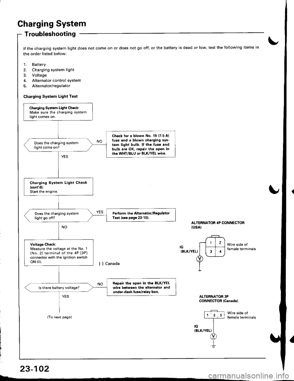
Charging System
Troubleshooting
It the charging system light does not come on or does not go off, or the battery is dead or low, test the following items in
the order listed below:
1. Battery
2. Charging system light
3. Voltage
4. Alternator control system
5. Alternator/regulator
Charging System Light Test
ALTERNATOR'P CONNECTORIUSAI
IGIBLK/YEL)
Wire side offemale terminals
Wire side offemale terminals
ALTERNATOR 3PCONNECTOR lCanadal
Charging System Light Check:Make sure the charging systemlight comes on.
Ch€ck tor a blown No. 15 (7.5 A)
tuse and . blown charging sys-
tem light bulb. ll the fuse andbulb are OK, .eptir tho open inlhe WHT/BLU or BLK/YEL wire.
Does the charging systemlight come on?
Ch.rging System Light Check(cont'd):
Start the engine.
Pertorm the Ahernator/RegulstolTest (s€. prge 23-101,Does the charging systemlight go off?
Voltago Check:Measure the voltage at the No. 1
lNo. 2l terminal of the 4P [3P]connector with tho ignition switchoN {lr).
Repair tho open in ih€ 8LK/YELwir6 betweon the alte]nator andundor-dash lure/reley box.
I4
L-*
23-102
Page 1161 of 1681
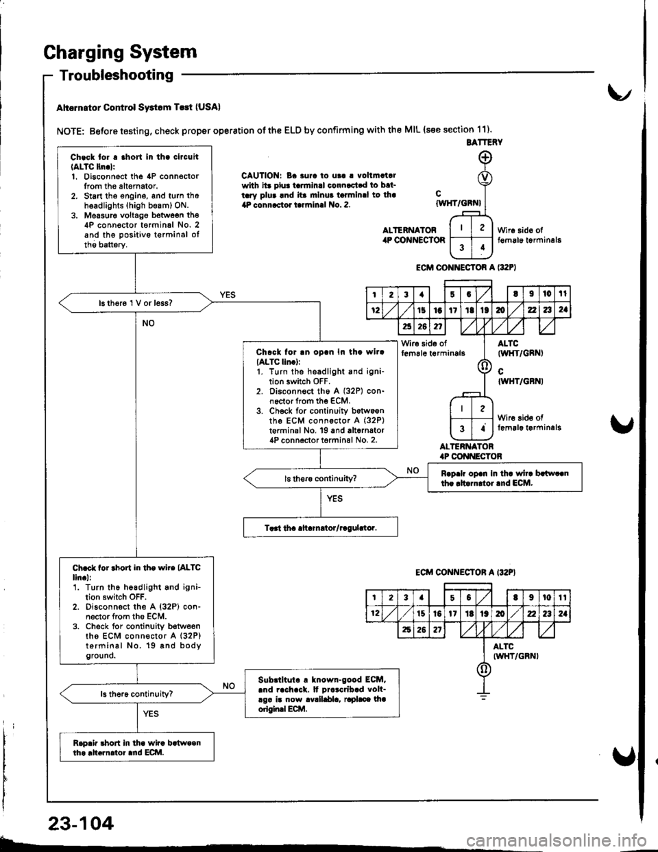
Gharging System
Troubleshooting
Ahcrn.tor Control Swtom T.rt (USA)
NOTE: Betore testing, check proper operation of the ELD by confirming with the MIL (s€e section 11).
CAUTION: Ba 3urc to ut! | vollmatalwith hr plu! tarmlnal connactad to bat-tary plua and ita mlnua talmlnal to lha4P connactor tarrninal No. 2.
ALTENNATORilP COiINECTOR
cIWHT/GBN}
ALTERNATOR.P CONI{ECTOB
Wire sido olt€m6le t€rminal6
ECM CONI{ECTOR A l:t2F)
BATTERY
Ch.ck tor . .hort In th. clrcuit(ALTC ltn.lr1. Disconnect the 4P connoctorIrom th6 altemator.2. Start tho engine, and turn thoh6adlights (high beam) ON.3. Moasur€ voltago botwoen th64P conn€ctor t6rminal No. 2and the positivo t€rminsl oltho batterv.
16 thor6 1 V or less?
Chrck for .n oD.n In th. wllrIALTC lln.):1. turn the headlight and igni-tion switch OFF.2. Disconnect th6 A (32P) con-noctor from the ECM.3. Ch6ck for continuity b6tw6entho ECM connoctor A (32P)
t€rminal No, 19 and alternator4P connoctor torminal No. 2.
Rrp.h op.n In th. wh. brlw..nth. rltarn oi.nd ECM.
Ch.ct for rhort in th. wire (ALTC
lin.l:'1. Turn the headlight and ignition switch OFF.2. Disconn€ct the A {32P} con-n6ctor from tho ECM.3. Check for conlinuity b€twoenths ECM connector A (32P)
terminal No. 19 8nd bodyground.
Slbrlltut. ! tnown-good ECM..nd rach.ck. It Drorcrlb.d volt-rgr ir now avalldla, raphce lhaorigin.l Ecilt.
Rap.ir 3hort in lha wira bstwaanth. .h.rnator ard ECI\|.
I23{5GtI|l0tl
72151aItIt136zla2a
a26n,/,V
Wir€ side offem6le t€rminals(l
ALTC(wl{T/GRNI
cIWHT/GBNI
Wire 3id€ offemal6 t€rminelg34
ECM CONNECTON A I32P}
t23a50t9t0tt
12t510l1Itt9mz2a2a
62621
ALTCIWHT/GRNI()
23-104
b-.
Page 1209 of 1681
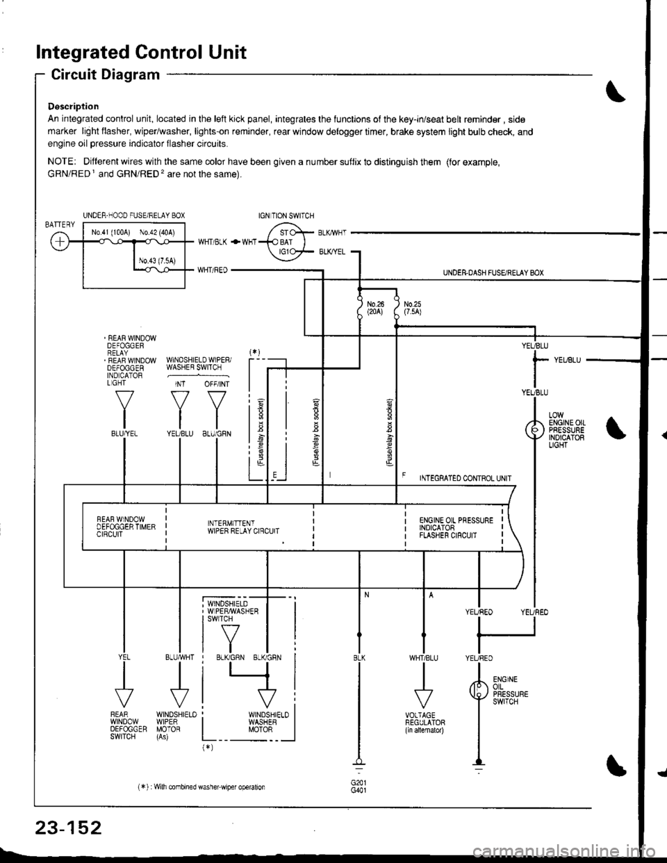
Integrated Control Unit
Circuit Diagram
Description
An integrated control unit, located in lhe left kick panel, integrates the lunctions of the key-in/seat belt r€minder , side
marker light llasher, wiper/washer, lights-on reminder, rear window delogger timer, brake system light bulb check, and
engine oil pressure indicator flasher circuits.
NOTE: Different wires with the same color have been given a nu mber suflix to distinguish them (for example,
GRN/RED I and GRN/RED'� are not the same).
REAR WINDOWDEFOGGERRELAYREAF WINDOWDEFOGGENIND CATORL GHT
f-7
IIBLU/YEL
WHT/ BLK
WHT/ REO
+WHT
WNDSHIELDWIPERiWASHER SWITCH
INT OFF/INT
f7 f7
tltlYEUBLU 8LU/GRN
BLUMHT
J
wtN0sHr€10WIPERMOTOR
UNDER.DASH FUSARETAY BOX
F rmecnlleo counoL ultr
YEUBLU
rYEUBLU
YEUREO YEUREO
tl
IYEURED
LOWENGINEOIIPRESSUREINOICATOBLIGHT
; WINDSHIELD' WIPERMASHERI swlTcH
tf7IVtlYEL
J
FEARwtN00wOEFOGGERSWITCH
WHTIBLU
J
VOTTAGEREGULATOR(ln allernatol)
BLK
G441
ENGINEolLPRESSUREswrTcH
UNDER-NOOO FUSE/RELAY BOX
1.6
:6
t;t-L
i
"'i'- 'i*-
|
I Il
I vi: WINDSHIELO II WASHEB I
L__ "oto: _ __l(*)
n
s
s
,]
23-152
(*) :Wilh combined washer-wiper operalion
Page 1213 of 1681
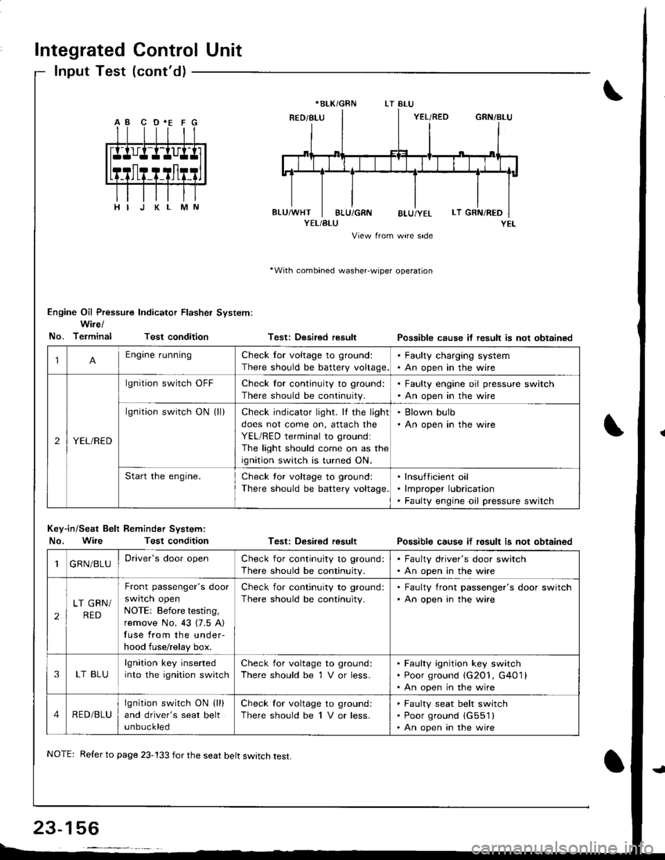
Integrated Control Unit
lnput Test (cont'd)
YEL/BLU
View from wire side
'With combined washer-wiper operation
Engine Oil Pressure Indicator Flasher System:
Wire/
No. TerminalTest condition
Key-in/Seat Belt Reminder System:
No. WileTest condition
Testi Desired result
Test: Desired result
Possible cause if result is not obtainsd
Possible cause if fesult is not obtained
*BLK/GRN
1Engine runningCheck for voltage to ground:
There should be battery voltage.
. Faulty charging system. An open in the wire
2YEL/RED
lgnition switch OFFCheck for continuity to ground:
There should be continuity.
. Faulty engine oil pressure switch. An open in the wire
lgnition switch ON (ll)Check indicator light. It the light
does not come on, attach the
YEL/RED terminal to groundl
The light should come on as the
ignition switch is turned ON.
. Blown bulb. An open in the wire
Start the engine.Check tor voltage to ground:
There should be battery voltage
lnsufticient oil
lmproper lubrication
Faulty engine oil pressure switch
1GRN/BLUDriver's door openCheck for continuity to ground:
There should be continuity.
. Faulty driver's door switch. An open in the wire
2
LT GRN/
RED
Front passenger's door
swrlcn open
NOTE: Before testing,
remove No. 43 {7.5 A)
fuse from the under-
hood fuse/relay box.
Check for continuity to ground:
There should be continuity.
. Faulty front passenger's door switch'An open in the wire
3LT BLU
lgnition key inserted
into the ignition switch
Check for voltage to ground:
There should be 1 V or less.
Faulty ignition key switch
Poor ground (G2O1, G401 l
An open in the wire
4RED/BLU
lgnition switch ON (lll
and driver's seat belt
unbuckled
Check for voltage to ground:
There should be 1 V or less.
Faulty seat belt switch
Poor ground (G551l
An open in the wire
NOTE: Refer to page 23-133 for the seat belt switch test.
Page 1313 of 1681
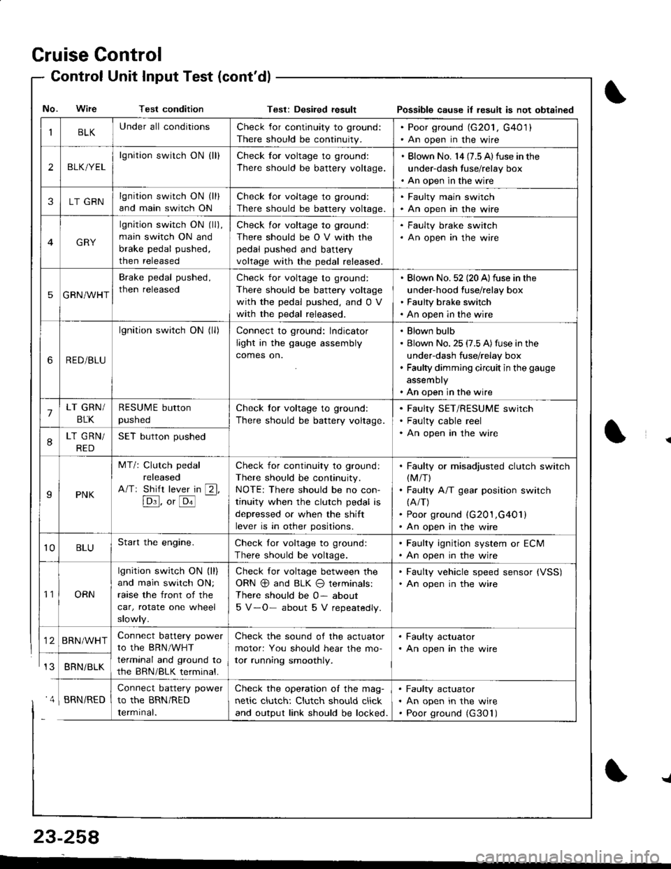
Cruise Control
- Control Unit InputTest(cont'dl
IBLKUnder all conditionsCheck for continuity to ground:
There should be continuity.
. Poor ground (G20l, G401). An open in the wire
2BLK/YEL
lgnition switch ON {ll}Check for voltage to ground:
There should be battery voltage.
. Blown No. l4 (7.5 Alfuse in the
under-dash fuse/relay box. An open in the wire
3LT GRNlgnition switch ON (ll)
and main switch ON
Check for voltage to ground:
There should be battery voltage.
. Faulty main swjtch. An open in the wire
GRY
lgnition switch ON (ll),
main switch ON and
brake pedal pushed,
then released
Check for voltage to ground:
There should be O V with the
pedal pushed and battery
voltage with the pedal released.
. Faulty brake switch. An open in the wire
5GRN/WHT
Brake pedal pushed,
then released
Check for voltage to ground:
There should be battery voltage
with the pedal pushed, and 0 V
with the pedal released.
Blown No. 52 (20 A)fuse in the
under-hood fuse/relay box
Faulty brake switch
An open in the wire
6RED/BLU
lgnition switch ON (ll)Connect to ground: lndicator
light in the gauge assembly
comes on.
Blown bulb
Blown No. 25 (7.5 A)fuse in the
under-dash fuse/relay box
Faulty dimming circuit in the gauge
assembly
An open in the wire
7LT GRN/
BLK
RESUME button
pushed
Check tor voltage to ground:
There should be battery voltage.
Faulty SET/RESUME switch
Faulty cable reel
An open in the wire8LT GRN/
RED
SET button pushed
IPNK
MT/: Clutch pedal
released
A/Tr Shift lever in [2l,
[Dl]. o, [o'l
-
Check for continuity to ground:
There should be continuity.
NOTE: There should be no con-
tinuity when the clutch pedal is
depressed or when the shift
lever is in other positions.
Faulty or misadjusted clutch switch(M/T)
Faulty A/T gear position switch(A/T)
Poor ground (G201,G401)
An open in the wire
't0BLUStart the engine.Check lor voltage to ground:
There should be voltage.
. Faulty ignition system or ECM. An open in the wire
't1ORN
lgnition switch ON (ll)
and main switch ON;
raase the front of the
car, rotate one wheel
slowly.
Check for voltage between the
ORN @ and BLK O terminals:
There should be 0- about
5 V-O- about 5 V repeatedly.
. Faulty vehicle speed sensor {VSS). An open in the wire
BRN/WHTConnect battery power
to the BRN/WHT
terminal and ground to
the BRN/BLK terminal.
Check the sound of the actuator
motor: You should hear the mo-
tor running smoothly.
. Faulty actuator. An open in the wire
BRNi BLK
Connect battery power
to the BRN/RED
Iermrnal.
Check the operation of the mag-
netic clutch: Clutch should click
and output link should be locked.
Faulty actuator
An open in the wire
Poor ground (G30'l)
No. Wire Test conditionTest: Desiled result Possible cause il lesult is not obtained
' 4 I BRN/RED
{
{
23-258
-L
Page 1390 of 1681
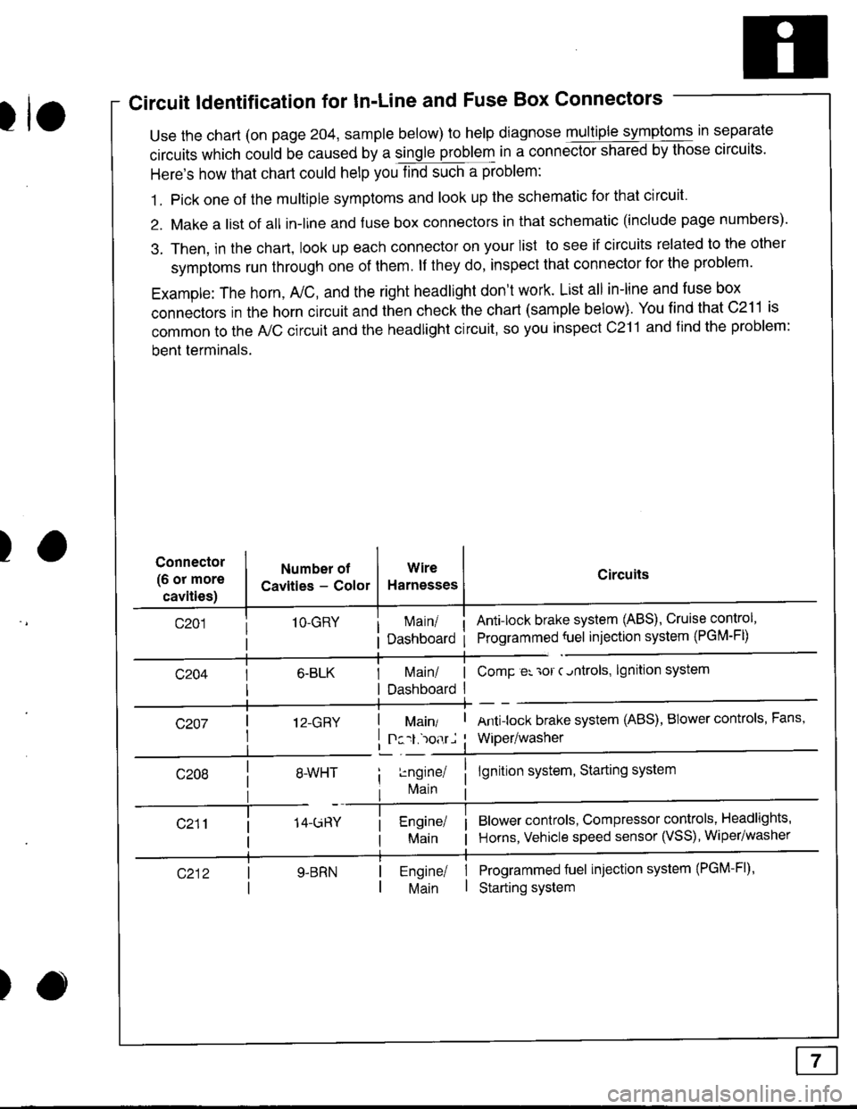
Circuit ldentification for In'Line and Fuse Box Connectors
tuse the chart (on page 204, sample below) to help diagnose multiple symptoms in separate
circuits which could be caused by a single problem in a connect,oishared by those circuits'
Here's how that chart could help you find such a problem:
1. Pick one of the multiple symptoms and look up the schematic for that circuit'
2. Make a list of all in-lrne and fuse box connectors in that schematic (include page numbers).
3. Then, in the chart, look up each connector on your list to see if circuits related to the other
symptoms run through one of them. lf they do, inspect that connector for the problem.
Example: The horn, A,/C, and the right headlight don't work. List all in-line and fuse box
connectors in the horn circuit and then check the chart (sample below). You find that C211 is
common to the A,/C circuit and the headlight circuit, so you inspect c211 and find the problem:
bent terminals.
)Connector
(6 or more
cavities)
Numbel of
Cavities - Color
1O-GRY
I 12-GRY
I
Wire
Harnesses
I Main/ | ComP er 'ror c.ntrols,
I Dashboard I
Circuits
Ant!lock brake system (ABS), Cruise control,
Programmed {uel injection system (PGM-FD
!ngrnei
lvlain
lgnition system
Antilock brake system (ABS), BIower controls, Fans,
Wiper/washer
lgnition system, Starting system
Blower controls, Compressor controls, Headlights'
Horns, Vehicle speed sensor (VSS), Wiper/washer
Programmed fuel injection system (PGM-Fl)'
Starting system
Engine/ |Main I
)