check engine light HONDA INTEGRA 1998 4.G User Guide
[x] Cancel search | Manufacturer: HONDA, Model Year: 1998, Model line: INTEGRA, Model: HONDA INTEGRA 1998 4.GPages: 1681, PDF Size: 54.22 MB
Page 306 of 1681
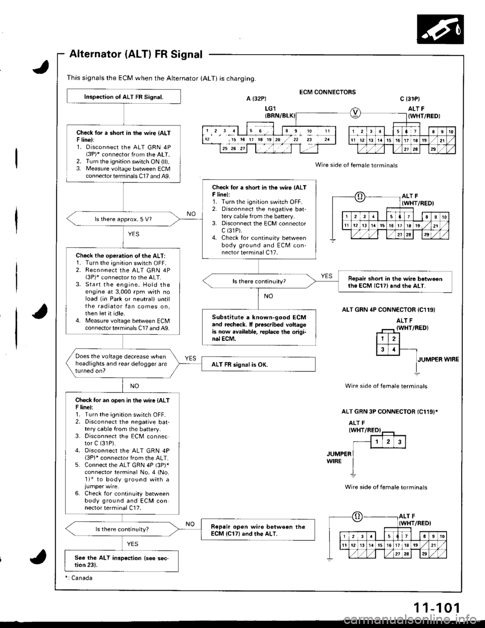
This signals the ECM when the Alternator (ALT) is charging.
Alternator (ALT) FR Signal
Check lor a short in th€ wire {ALTF line):1. Oisconnect the ALT GRN 4P(3P)* connector from the ALT.2. Turn the ignition switch ON {ll).3. Measure voltage between ECMconnector terminals C17 and A9.
ECM CONNECTORSA t32Pt
LG1
c 13lPl
ALT F(WHT/FEDI
Wire side of female terminals
ALT GRN 4P CONN€CTOR {C119}
JUMPER WIRE
Wire side of female terminals
ALT GRN 3P CONNECTOB {C119)*
JUMP€RWIRE
Wire side ot female terminals
12 15 t6 rr t8 19I
?
oALT F(WHT/REOI
23aI10
t112t3t5l6r819 ,/21
./,/,/2a29
[,ALT FIWHT/RED)
12339
11 12l517 tla19 ,/21
Inspection of ALT FR Signal.
Check for a shon in the wire {ALTF line):1. Turn the ignition switch OFF.2. Disconnecl the negative baatery cable from the battery.3. Disconnect the ECM connectorc (31P).
4. Check for continuity betweenbody ground and ECM con-nector terminal C17.
ls there approx.5 V?
Check the operation ofthe ALT:1. Turn the;Onition switch OFF-2. Reconnect the ALT GRN 4P(3P)* connector to the ALT.3. Start the engine. Hold theengine at 3,000 rpm wkh noload {in Park or neutral) untilthe radiator fan comes on,then let it idle.4. Measure voltage bet/veen ECMcon nector termina ls C17 and A9.
Ropair short in the wir6 betweenth6 ECM (C17) and the ALT.
Substitute a known-good ECMand recheck. It prescribed voltagGis now available, replace th€ origi-nal ECM.
Does the voltage decrease whenheadlights and rear defogger areturned on?ALT FR signal is OK.
Check tor an open in the wire {ALTF line):1. Turn the ignition switch OFF-2. Disconnect the negative bat-tery cable from the battery.3. Disconnect the ECM connector C (31P).
4. Disconnect the ALT GRN 4P(3Pi* connector from the ALT.5. Connect the ALT GRN 4P (3p)*
connector terminal No. 4 (No.'l)* to body ground with a
6. Check for continuity betweenbody ground and ECM connector terminal C17.
Ropair open wire bstw€an theECM {C17} and rhe ALT.ls there continuity?
ri Canada
11-101
Page 316 of 1681
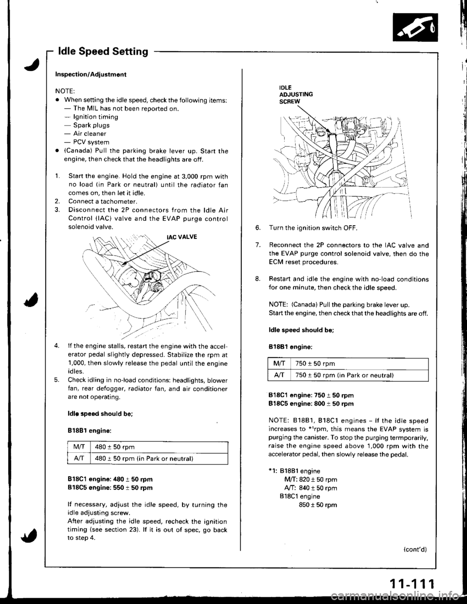
ldle Speed Setting
IDLEADJUSTINGSCREW
7.
6.Turn the ignition switch OFF.
Reconnect the 2P connectors to the IAC valve and
the EVAP purge control solenoid valve, then do the
ECM reset procedures.
Restart and idle the engine with no-load conditions
for one minute, then check the idle speed.
NOTE: (Canada) Pullthe parking brake lever up.
Start the engine, then check that the headlights are off.
ldle speed should be;
Bl88l €ngine:
Mfi750 i 50 rpm
A/T750150 rpm (in Park or neutral)
818C1 engine:750 i 50 rpm
818C5 engine: 800 i 50 rpm
NOTE: 81881, Bl8Cl engines - It the idle speed
increases to *1rpm, this means the EVAP system ispurging the canister. To stop the purging termporarily.
raise the engine speed above 1,000 rpm with the
accelerator pedal, then slowly release the pedal.
*1: 81881 engine
M/T: 820 i 50 rpm
Ay'T: 840 t 50 rpm
818Cl engine
850 I 50 rpm
(cont'd)
Inspection/Adiustmont
NOTE:
. When setting the idle speed, checkthe following items:- The MIL has not been reported on.- lgnition timing
Spark plugs- Air cleaner- PCV system
. (Canada) Pull the parking brake lever up. Start the
engine, then check that the headlights are off.
1. Start the engine. Hold the engine at 3,000 rpm with
no load (in Park or neutral) until the radiator fan
comes on, then let it idle,
Connect a tachometer.
Disconnect the 2P connectors from the ldle Air
Control (lAC) valve and the EVAP purge control
solenoid valve.
2.
5.
if the engine stalls, restan the engine with the accel
erator pedal slightly depressed. Stabilize the rpm at
1,000, then slowly release the pedal until the engine
idles.
Check idling in no-load conditions: headlights, blower
fan, rear defogger, radiator fan, and air conditioner
are not ope€tlng.
ldlo speed should be;
B188l engine:
Mlf480 :l 50 rpm
A/T480 i 50 rpm (in Park or neutral)
B18C1 engine: /t80 t 50 rpm
818C5 sngine:550 t 50 rpm
lf necessary, adjust the idle speed, by turning theidle adjusting screw.
After adjusting the idle speed, recheck the ignition
timing {see section 23). lf it is out of spec, go back
to steo 4.
Page 317 of 1681
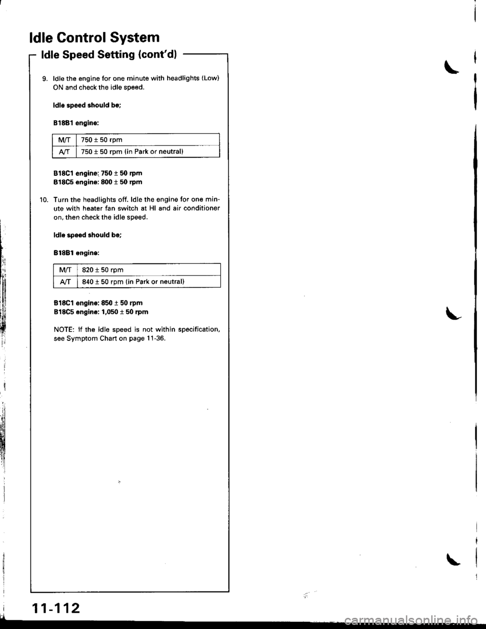
ldle Control System
ldle Speed Setting (cont'dl
ldle the engine for one minute with headlights (Low)
ON and check the idle speed.
ldle 3peed should b€;
B1881 engine:
MIT750 t 50 rpm
750 i 50 rDm (in Park or neutrall
818C1 engine: 7501 50 nm
818C5 engine: 8001 50 rpm
Turn the headlights off. ldle the engine for one min-
ute with heater fan switch at Hl and air conditioner
on, then check the idle speed.
ldl. spood should be;
Bl8Bl ongin.:
M/T820 i 50 rpm
lvT840 t 50 rpm (in Park or neutral)
818C1 €ngino: 850 i 50 rpm
818C5 engino: 1,050 t 50 rpm
NOTE: lf the idle speed is not within specification.
see Symptom Chart on page 1!-36.
\
L
i
lIh:
lffiiltfl!
ffi
| 11-112
\
I
Page 343 of 1681
t"iI
Emission Gontrol System
System Description
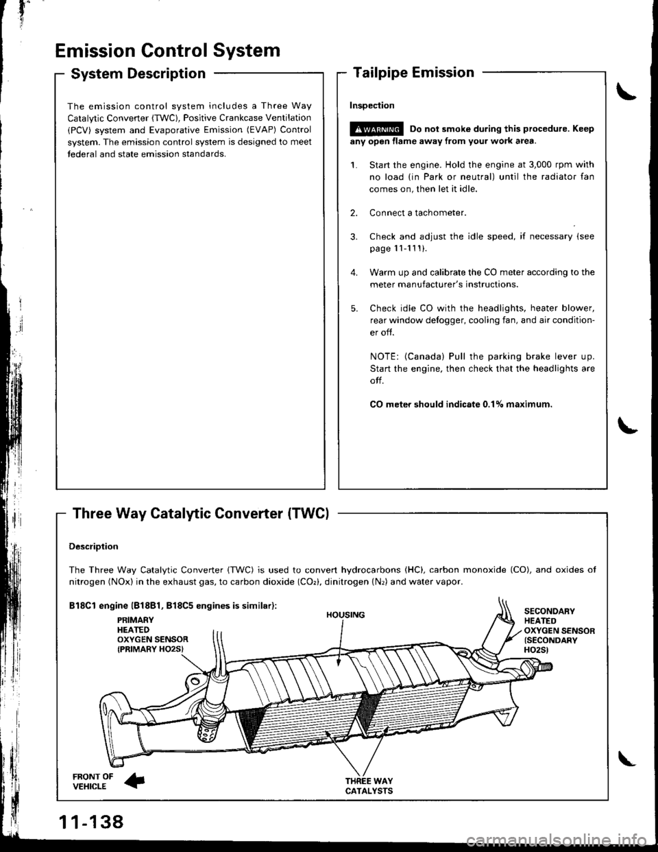
Three Way Catalytic Converter (TWCI
\
t
The emission control system includes a Three Way
Catalytic Converter (TWC), Positive Crankcase Ventilation
(PCV) system and Evaporative Emission (EVAP) Control
system. The emission control system is designed to meet
tederal and state emission standards.
InsDeciion
!@@ Do not smoke during this procedure. Keep
any open llame away from your work area.
1. Start the engine. Hold the engine at 3,000 rpm with
no load {in Park or neutral) until the radiator fan
comes on, then let it idle.
2. Connect a tachometer.
Check and adjust the idle speed, if necessary (see
page '11-11 ! ).
Warm up and calibrate the CO meter according to the
meter manufacturer's instructions.
Check idle CO with rhe headlights, heater blower,
rear window defogger, cooling fan, and air condition-
er off.
NOTE: {Canada) Pull the parking brake lever up.
Start the engine, then check that the headlights are
olf.
CO meter should indicste 0.17o maximum.
DescriDtion
The Three Way Catalytic Converter {TWC) is used to convert hydrocarbons (HC), carbon monoxide (CO), and oxides of
nitrogen (NOx) in the exhaust gas, to carbon dioxide (COr), dinitrogen {Nr) and water vapor.
Bl8Cl engine l818Bl, 818C5 engines is similar):
FRONT OFVEHICLE
PRIMAEYHEATEDOXYGEN SENSORIPRIMARY HO2S}
HOUSING
WAYCATALYSTS
SECONOARYHEATEDOXYGEN SENSOR{SECONDARYH02St
\
Page 345 of 1681
'il
Emission Gontrol System
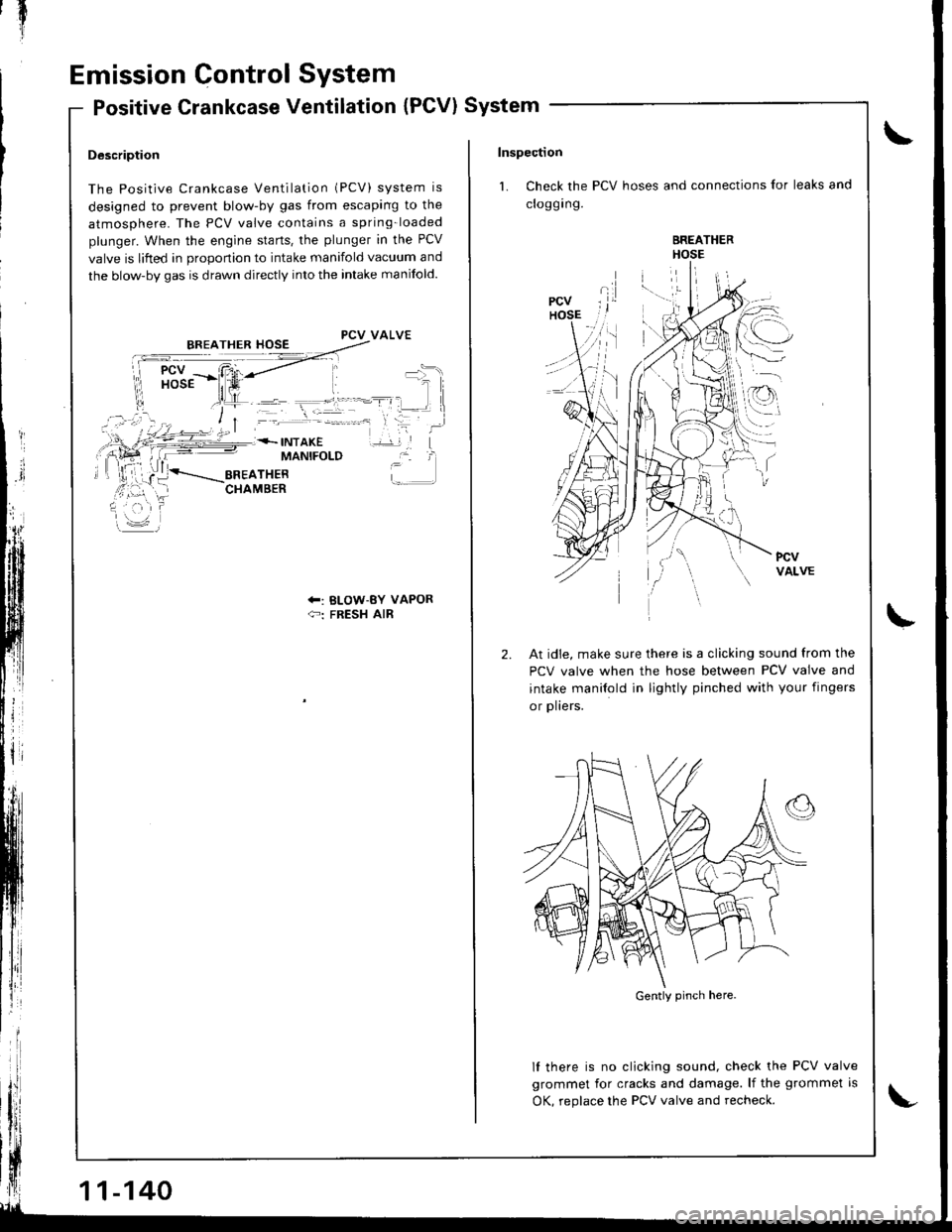
Positive Crankcase Ventilation (PCV) System
Description
The Positive Crankcase Ventilation (PCV) system is
designed to prevent blow-by gas from escaping to the
atmosphere. The PCV valve contains a spring-loaded
plunger. When the engine starts. the plunger in the PCV
valve is lifted in orooonion to intake manifold vacuum and
the blow-by gas is drawn directly into the intake manifold.
PCV VALVE
MANIFOLD
+: BLOW-BY VAPOR{-: FRESH AIR
11-140
Inspection
1. Check the PCV hoses and connections for leaks and
croggrng.
BREATHERHOSE
l.--:\
,.r
I
2.At idie, make sure there is a clicking sound from the
PCV valve when the hose between PCV valve and
intake manilold in lightly pinched with your fingers
or plters.
lf there is no clicking sound, check the PCV valve
grommet for cracks and damage. lf the grommet is
OK, reolace the PCV valve and recheck.
Gently pinch here.
Page 372 of 1681
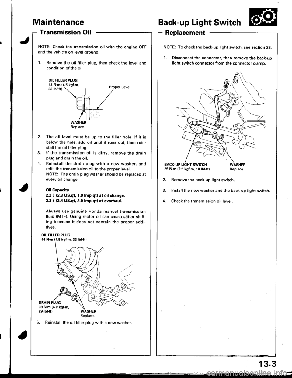
aintenance
Transmission Oil
NOTE: Check the transmission oil with the engine OFF
and the vehicle on level ground.
1. Remove the oil filler plug, then check the level and
condition of the oil.
OIL FILLER PLUG44 N.m {4.5 kgf.m,Proper Level33 tbf.ftl
The oil level must be up to the filler hole. lf it is
below the hole, add oil until it runs out, then rein-
stall the oil filler plug.
lf the transmission oil is dirty, remove the drainplug and drain the oil.
Reinstall the drain plug with a new washer, and
refillthe transmission oilto the proper tevet.
NOTE: The drain plug washer should be replaced at
every oil change.
Oil Capacity
2.2 | i.2.3 US.qr,1.9 lmp.qtl at oil ch.nge.
2.3 t l2.1US.qt,2.O lmp.qtl at ovorhaul.
Always use genuine Honda manual transmission
fluid (MTF). Using motor oil can causa€tiffer shift-
ing because it does not contain the proper addi-
Back-up Light Switch
Replacement
NOTE: To check the back-up light switch. see section 23.
1. Disconnect the connector, then remove the back-up
light switch connector from the connector clamp.
l.m {2.5 kgf.m, 18lbf.ft) Replace.
Remove the back-up light switch.
Install the new washer and the back-up light switch.
Check the transmission oil level.
!ves.
OIL FILLER PLUG
DRAIN PLUG39 N.m {4.0 kg{.m,29 rbf.ftlReplace.
5. Reinstall the oil filler plug with a new washer,
Replace.
EACK.UP LIGHT SWITCH25 N.m {2.5 kgf.m, 18 lbf.ft)
13.3
Page 471 of 1681
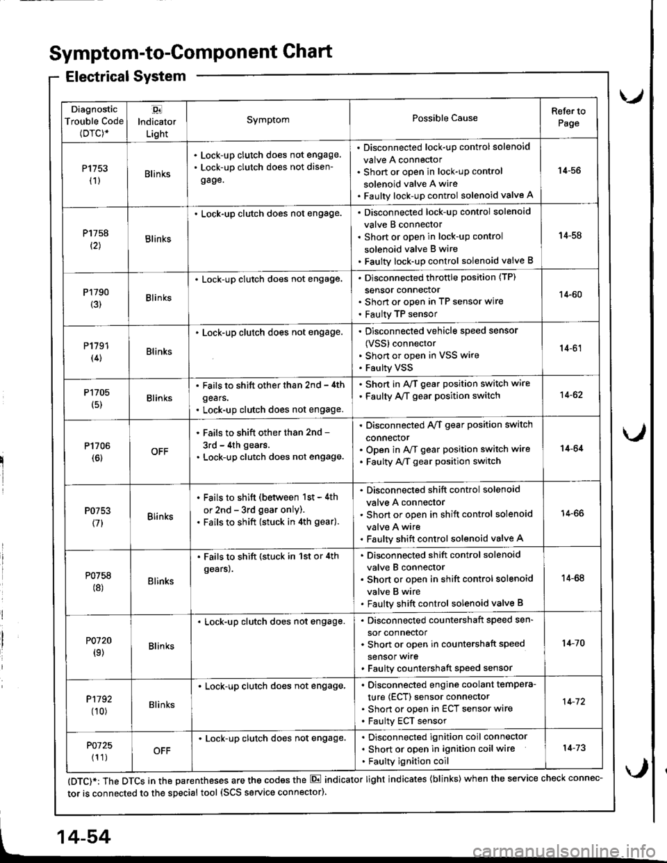
Diagnostic
Trouble Code(Drc)*
,94
lndicator
Light
SymptomPossible CauseRefer to
Page
P1153(1)Blin ks
Lock-up clutch does not engage,
Lock-up clutch does not disen-
gage.
Disconnected lock-up control solenoid
valve A connector
Short or open in lock-uP control
solenoid valve A wire
Faulty lock-up control solenoid valve A
14-56
P1758
t2lBlinks
. Lock-up clutch does not engage.Disconnected lock-up control solenoid
valve B connector
Short or open in lock-uP control
solenoid valve B wire
Faulty lock-up control solenoid valve B
14-58
P1790(3)Blinks
. Lock-up clutch does not engage.Disconnected throttle position (TP)
sensor connector
Short or open in TP seflsor wire
Faulty TP sensor
14-60
P1191(4)Blinks
. Lock-up clutch does not engage.Disconnected vehicle speed sensor
{VSS} connector
Shon or open in VSS wire
Faulty VSS
14-61
P1705
(5)Blinks
. Fails to shift other than 2nd - 4th
gears.
. Lock-up clutch does not engage.
. Shod in AvT gear position switch wire
. Faulty A,/T gear position switch14-62
P1706(6)OFF
' Fails to shift other than 2nd -
3rd - 4th gears.
. Lock-up clutch does not engage.
Disconnected A/T gear position switch
connector
Open in A/f gear position switch wire
Faulty A/f gear position switch
14-64
P0753
(71Blinks
. Fails to shift (between 1st - 4th
or 2nd - 3rd gear only).. Fails to shift (stuck in 4th gear).
Disconnected shift control solenoid
valve A connector
Short or open in shift control solenoid
valve A wire
Faulty shift control solenoid valve A
14-66
P0758(8)Blinks
. Fails to shift (stuck in 1st or 4th
gears).
Disconnected shift control solenoid
valve B connector
Short or open in shift control solenoid
valve B wire
Faulty shift control solenoid valve B
14-68
P0120(9)Blin ks
Lock-up clutch does not engage.Disconnected countershaft speed sen-
sor connector
Short or open in countershaft speed
sensor wrre
Faulty countershaft speed sensor
1+10
P1192
00)Blinks
. Lock-up clutch does not engage,Disconnected engine coolant tempera-
ture (ECT) sensor connector
Short or open in ECT sensor wire
Faulty ECT sensor
14-72
P0725
{1 1)OFF
Lock-up clutch does not engage.Disconnected ignition coil connector
Short or open in ignition coil wire
Faulty ignition coil
14-73
Symptom-to-ComPonent Chart
Electrical System
(DTC)*: The DTCS in the parentheses are the codes the E indicator light indicates {blinks) when the service check connec-
tor is connected to the special tool (SCS service connector)
4-54
Page 489 of 1681
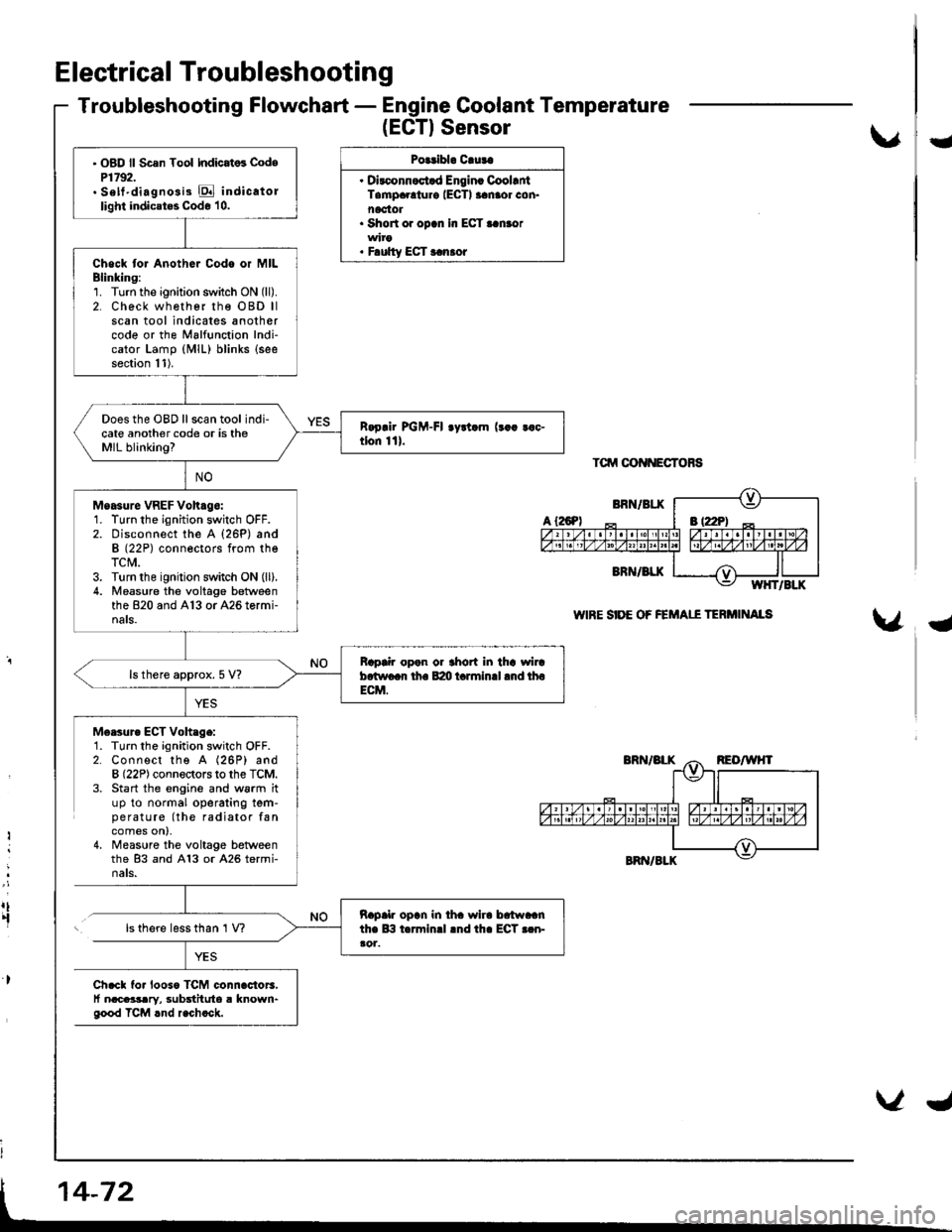
Electrical Troubleshooting
Troubleshooting Flowchart - Engine Coolant Temperature
(EGTISensor
Polribl. Cluta
. Dirconnoct.d Engin. CoollntTampaolur€ IECTI aanaor con.noctot. Short or opcn In ECT..n.or
. F.ulty ECT r.n.or
Tctrrt oot{NEcToRs
WIRE SIDE OF FEMAII TERi'IINAIS
U
{
M6esur. ECT Voh.ge:1. Turn the ignition switch OFF.2. Connect the A (26P) andB (22P) connectors to the TCM.3. Start the engine and w6rm ituP to normal operating tem-pe ratu re (the radiator fancomes on),4, Measure the voltage betweenthe 83 and A13 or A26 termi-nats.
Ii
:
rt.fls there less than 1 V?
Ch.cl fo. looso TCM connac{or3,t nacaasary, substituto a known"good TCM rnd r.chock.
' OBD ll Scsn Tool Indicat6 CodeP1792.. Sett'diagno3i3 E indicatollight indicates Code 10.
Chock tor Anothor Codo or MILBlinking:1. Turn the ignition switch ON (ll).
2. Check wh€ther rhe OBD llscan tool indicates anothercode or the Malfunction Indi-cator Lamp (MlL) blinks (see
section 11).
Does the OBD ll scan tool indi-cate another code or is theMIL blinking?
Moasure VREF Voh.go:1. Turn the ignition switch OFF.2. Disconnect the A {26P) andB (22P) conneotors from theTCM.3. Turn the ignition switch ON (ll).
4. Measu.e the voltage betweenthe 820 and A13 or A26 tormi-nals.
Bap|ir open or thort in tha wircb.two.r th. B:m t.rminll .nd thoECM.
ls there approx. 5 V?
napalr opln in iha wlra brtwaanthe lB t.rminrl lnd th. ECT r.n-ao1.
Page 493 of 1681
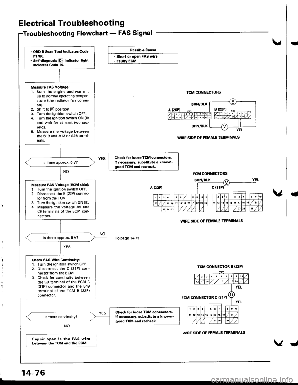
. OBD ll Scan Tool indicatcs CodeP1786.. Soff-diagnGis E indicrtor lightindicat6 Codo '1,0.
M6a3ure FAS Vottago:1. Start the engine and warm itup to normal operatang temPer_6ture (the radiator fan comeson).2. shift to E position.
3. Turn the ignition switch OFF.4. Turn the ignition switch ON (ll)
and wait lor at least two sec-onds.5. Measlre the voltage betweenthe 819 and A13 or A26 termi-nals.
Chsck for loo3r TCM connactot!.lf necoslary, lubsihuto a known.good TCM rnd r.chrck,ls there approx. 5 V?
M6asuro FAs vohagoIECM sidol:1. Turn the ignition switch OFF.
2. Disconnect the B (22P) connec-tor lrom the TCM.3. Turn the ignition switch ON (ll).
4. Measure the voltage Ag andC9 terminals of tho ECM con-nectors.
ls there approx. 5 V?
Chock for loore TCM connectoE.lf noceilary, subrtitula a known-good ICM rnd rcchock.
Repair opon in the FAS wircb€(we€n the TCM snd ths ECM.
Electrical Troubleshooting
Troubleshooting Flowchart - FAS Signal
vU
PG.iblo Cru!.
. Short o. opon FAS wira. Feoltv ECM
To page 14-75
TCM CONNECTORS
WIRE SIDE OF FEMALE TERMINALS
WIRE SIDE OF FEMAI.T TEBMINAI-S
WIRE SIDE OF FEMALE TERMINALS
a
,i,I
Chock FAS Wiro Continuity:1. Turn the ignition switch OFF.2. Disconnect the C (31P) con-nector lrom the ECM.3. Check lor continuity betweenthe C9 terminal of the ECM C(31P) connector and the 819terminal of the TCM B (22P)
14-76
ECM CONNECTORS
ECM CONNECTOR C I31P}
Page 507 of 1681
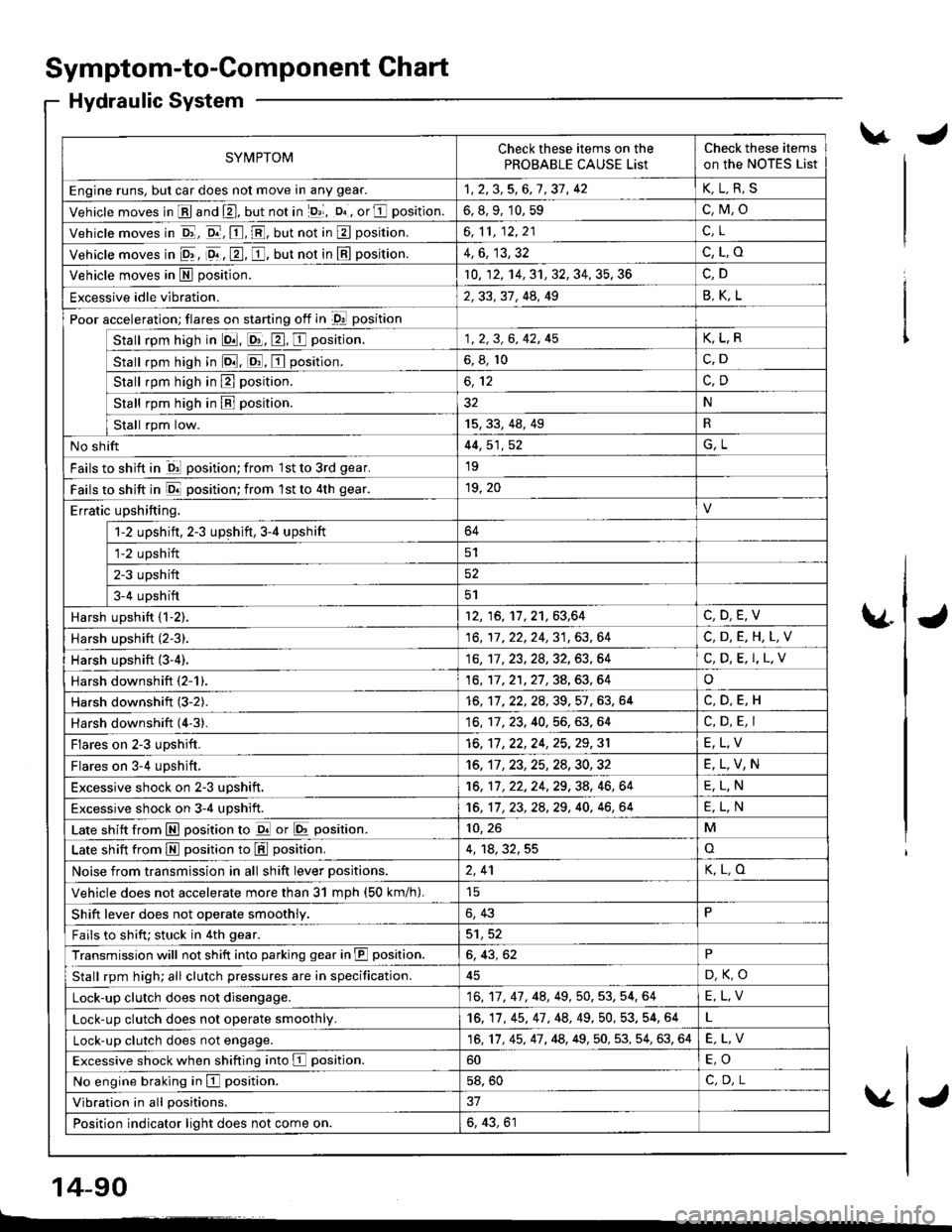
Symptom-to-Component Chart
Hydraulic System
SYMPTOMCheck these items on the
PROBABLE CAUSE List
Check these items
on the NoTES List
Engine runs, but car does not move in any gear.1,2,3,5,6,7,37, 42K,L.R,S
Vehicle moves in E and E, but not in lD,l, D. , or E position.6, 8, 9, 10, 59c,M,o
Vehicle moves in E, o.-, E, E, but not in E position.6,11,12,21c.L
Vehicle moves in 9r, 9. , E, E, but not in E position.4,6, 13,32c,L,o
Vehicle moves in E position.10, 12, 14, 31, 32, 34, 35, 36
Excessive idle vibration.2,33, 31, 44, 49B,K,L
Poor acceleration; flares on starting off in D! position
Stall rpm high in lQ|. E, E, E position.1, 2, 3, 6, 42, 45K,L,R
stall rpm high in lo.tl. ld, E position.6, 8, 10c.D
Stall rpm high in E position.
Stall rpm high in B position.32N
tat"tkp,ril"*'15,33,48,49R
No shift44, 51, 52G,L
Fails to shift in ql position; from 1st to 3rd gear.19
Fails to shift in E position; from lst to 4th gear.19, 20
Erratic upshifting.
1-2 upshift, 2-3 upshift,3-4 upshift64
fiz upshift
ETupshift52
Ia-+ upstrifi5l
Harsh upshift {1-2).12, 16, 11,21,63,64C,D,E,V
Harsh upshift (2-3).16,17,22,24,31,63,64C,D,E.H,L,V
Harsh upshift (3-4).16,'�tl. 23, 28, 32, 63, 64C, D, E. I,L.V
Harsh downshift (2-1).16, 17,21,27,34,63,64o
Harsh downshift (3-2).16, 11 ,22,2A,39,57 ,63, 64
Harsh downshift (4'3).16, 17, 23. 40, 56, 63. 64C, D, E, I
Flares on 2-3 upshift.16, 17 ,22,24, 25,29,31E,L,V
Flares on 3-4 upshift,16, 11 ,23,25,24,30,32E,L,V,N
Excessive shock on 2-3 uDshift.16, 11, 22, 24, 29, 38, 46, 64E,L.N
Excessive shock on 3-4 upshift.16, 11 , 23, 2a,29, 40, 46, 64E,L,N
Late shift from E position to d or E position.10, 26M
Late shift from M position to L!!l position.4, 18,32,55o
Noise from transmission in all shift lever Dositions.2,41K,L,O
Vehicle does not accelerate more than 31 mDh (50 km/h).
Shift lever does not operate smoothly.6, 43P
Fails to shifu stuck in 4th gear.5'1,52
Transmission will not shift into parking gear in JII position.6, 43, 62P
Stall rpm high; all clutch pressures are in specification.D,K,O
Lock-up clutch does not disengage.16,17, 47, 48,49, 50, 53, 54, 64E,L,V
Lock-up clutch does not operate smoothly.16, 17, 45, 47 , 48, 49,50, 53. 54, 64
Lock-up clutch does not engage.16,17, 45, 47, 48, 49,50, 53, 54, 63, 64E,L,V
Excessive shock when shifting into E position.60
No engine braking in E position.58, 50C,D.L
Vibration in all positions.
Position indicator light does not come on.6, 43, 61
\.J
\4J
v
14-90
L------�
J