lock HONDA INTEGRA 1998 4.G Workshop Manual
[x] Cancel search | Manufacturer: HONDA, Model Year: 1998, Model line: INTEGRA, Model: HONDA INTEGRA 1998 4.GPages: 1681, PDF Size: 54.22 MB
Page 1645 of 1681
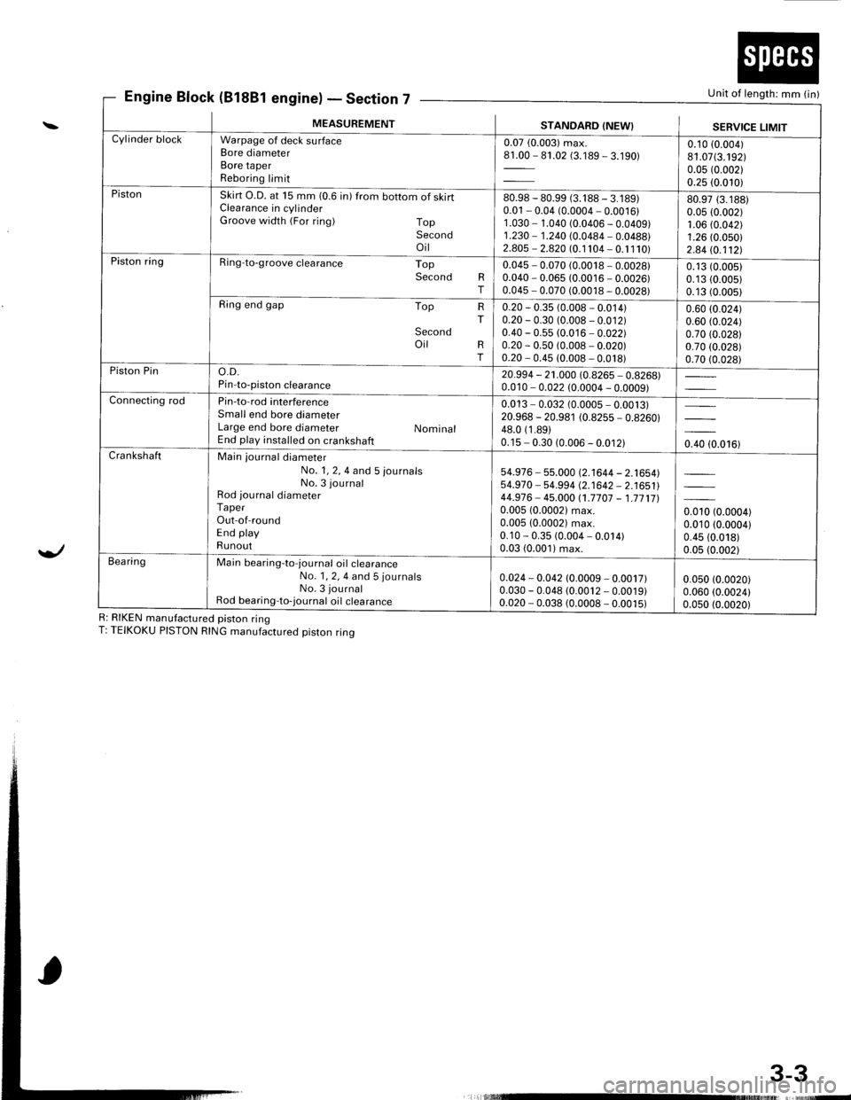
Engine Block (81881 engine)Section 7Unit of length: mm (in)
3-3
\
Yl
R: RIKEN manufactured piston ringT: TEIKOKU PISTON RING manufactured piston ring
E' - Declror
MEASUREMENTSTANDARD (NEW}SERVICE LIMITCylinder blockWarpage of deck surfaceBore diameterBore taperReboring limit
0.07 (0.003) max.81.00 - 81.02 (3.189 - 3.190)0.10 (0.004)
81.07(3.192)0.05 (0.002)
0.25 (0.010)PistonSkirt O.D. at 15 mm (0.6 in) from bottom of skirtClearance in cylinderGroove width (For ring) TopSecondoil
80.98 - 80.99 (3. 1 88 - 3. 1 89)0.01 - 0.04 (0.0004 - 0.0016)1 .030 - 1.040 (0.0406 - 0.0409)1.230 - 1.240 (0.0484 - 0.0488)2.805 - 2.820 (0.1 104 - 0. 1 1 10)
80.97 (3.188)
0.05 (0.002)1.06 (0.042)
1.26 (0.050)
2.84 (0.112!.Piston ringRing-to-groove clearance TopSecond RT
0.045 - 0.070 (0.0018 - 0.0028)0.040 - 0.065 (0.0016 - 0.0026)0.045 - 0.070 (0.0018 - 0.0028)
0.13 (0.0051
0.13 (0.005)
0.13 (0.005)
Ring end gap Top
Secondoil
HT
RT
0.20 - 0.35 (0.008 - 0.014)0.20 - 0.30 (0.008 - 0.012)0.40 - 0.55 (0.016 - 0.022)0.20 - 0.50 (0.008 - 0.020)0.20 - 0.45 (0.008 - 0.018)
0.60 (0.024)
0.60 (0.024)
0.70 (0.028)
0.70 (0.028)
0.70 (0.028)Piston Pino.D.Pin-to-piston clearance20.994 - 21.000 (0.8265 - 0.8268)0.010 - 0.022 (0.0004 - 0.0009)Connecting rodPin-to-rod interferenceSmall end bore diameterLarge end bore diameter NominalEnd play installed on crankshaft
0.013 - 0.032 (0.0005 - 0.0013)20.968 - 20.981 (0.8255 - 0.8260)48.0 (1 .89)0.15 - 0.30 (0.006 - 0.012)0.40 (0.016)CrankshaftMain journal diameterNo. 1, 2, 4 and 5 journalsNo. 3 journalRod journal diameterTaperOut-of-roundEnd playRunout
54.976 - 55.000 (2.1644 - 2.1654)54.970 - 54-994 (2.1642 - 2.1651144.976- 45.000 (1.7707 - 1.771710.005 (0.00021 max.0.005 (0.0002) max.0.10 - 0.35 (0.004 - 0.014)0.03 (0.001) max.
0.010 (0.0004)0.010 (0.0004)
0.45 (0.018)
0.05 (0.002)Bea ringMain bearing-to-journal oil crearanceNo. 1, 2, 4 and 5 journalsNo. 3 journalRod bearing-to-journal oil crearance
0.024 - 0.042 (0.0009 - 0.0017)0.030 - 0.048 (0.0012 - 0.0019)0.020 - 0.038 (0.0008 - 0.0015)
0.050 (0.0020)
0.060 (0.0024)0.0s0 (0.0020)
L rlllllllllrltruE
Page 1647 of 1681
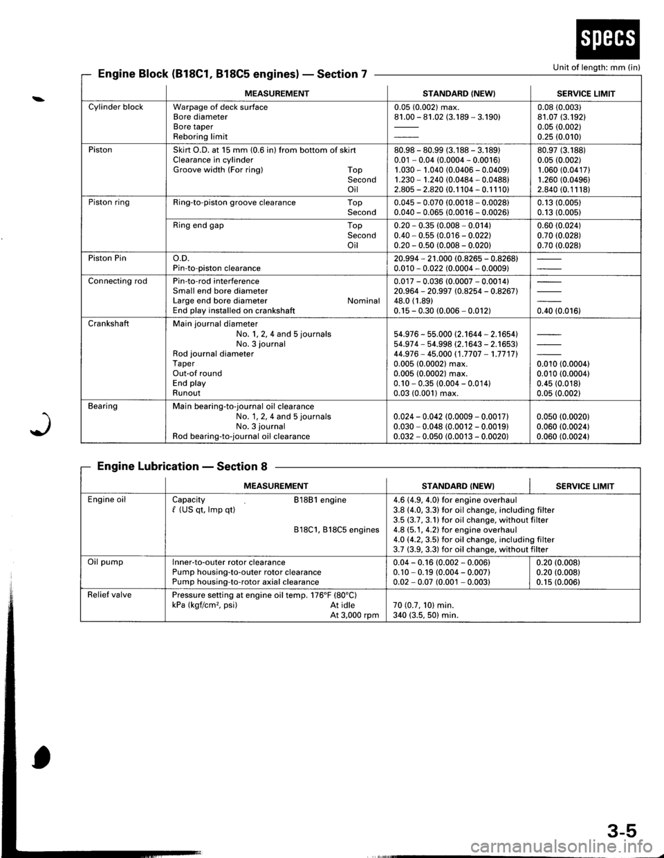
Unit of length: mm (in}
J
Engine Block (818C1, 818C5 engines)Section 7
Engine LubricationSection 8
MEASUREMENTSTANDARD (NEW} I SERVICE LIMIT
Cylinder blockWarpage of deck surfaceBore diameterBore taperReboring limit
0.05 (0.002) max.81.00 - 81.02 (3.189 - 3.190)0.08 (0.003)
81.07 (3.192)
0.05 (0.002)
0.25 (0.010)
PistonSkirt O.D. at 15 mm (0.6 in) from bottom of skirtClearance in cylinderGroove width (For ring) TopSecondoil
80.98 - 80.99 (3.188 - 3.18910.01 - 0.04 (0.0004 - 0.0016)1.030 - 1.040 (0.0406 - 0.0409)1.230 - 1.240 (0.0484 - 0.0488)2.805 - 2.820 (0.1 104 - 0.1 1 10)
80.97 (3.188)
0.05 (0.002)
1.060 (0.04171
1.260 (0.0496)
2.840 (0.11181
Piston ringRing-to-piston groove clearance TopSecond0.045 - 0.070 (0.0018 - 0.0028)0.040 - 0.065 (0.0016 - 0.0026)0.13 (0.005)
0.13 (0.005)
Ring end gap TopSecondoil
0.20 * 0.35 (0.008 - 0.014)0.40 - 0.55 (0.016 - 0.022)0.20 - 0.50 (0.008 - 0.020)
0.60 (0.024)
0.70 (0.028)
0.70 (0.028)
Piston Pino.D.Pin-to-piston clearance20.994 - 21 .000 (0.8265 - 0.8268)0.010 - 0.022 (0.0004 - 0.0009)
Connecting rodPin-to-rod interferenceSmall end bore diameterLarge end bore diameter NominalEnd play installed on crankshaft
0.017 - 0.036 (0.0007 - 0.0014)20.964 - 20.997 (0.8254 - 0.8267)48.0 (1.89)
0.15 - 0.30 (0.006 - 0.012)0.40 (0.016)
CrankshaftMain journal diameterNo. 1, 2, 4 and 5 journals
No. 3 journalRod journal diameterTaperOut-of roundEnd playRunout
54.976 - 55.000 (2.1644 - 2.1654)54.97 4 - 54.998 (2.1643 - 2.1653)44.976- 45.000 (1.7707 -1.7717l.
0.005 (0.0002) max.0.005 (0.0002) max.0.10 - 0.35 (0.004 - 0.014)0.03 (0.001) max.
orro to.ooool0.010 (0.0004)
0.45 (0.018)
0.05 (0.002)
BearingMain bearing-to-journal oil clearanceNo. 1, 2, 4 and 5 journals
No. 3 journal
Rod bearing-to-journal oil clearance
0.024 - 0.042 (0.0009 - 0.0017)0.030 - 0.048 (0.0012 - 0.0019)0.032 - 0.050 (0.0013 - 0.0020)
0.050 (0.0020)
0.060 (0.0024)
0.060 (0.0024)
MEASUREMENTSTANDARD (NEW}SERVICE LIMIT
Engine oilCapacity 81881 engine/ (US qt, lmp qt)
818C1, B18C5 engines
4.6 (4.9, 4.0) for engine overhaul3.8 (4.0, 3.3) for oil change, including filter3.5 (3.7,3.1)for oil change, without filter4.8 (5.1, 4.2) for engine overhaul4.O (4.2,3.5) for oil change. including filter3.7 (3.9, 3.3) for oil change, without filter
Oil pumplnner-to-outer rotor clearancePump housing-to-outer rotor clearancePump housing-to-rotor axial clearance
0.04 - 0.16 (0.002 - 0.006)0.10 - 0.19 (0.004 - 0.007)0.02 - 0.07 (0.001 - 0.003)
0.20 (0.008)
0.20 (0.008)
0.1s (0.006)
Relief valvePressure setting at engine oil temp. 176'F (80"C)
kPa (kgf/cm,. psi) At idleAt 3,000 rpm70 (0.7, 101 min.340 (3.5, 50) min.
3-5
Page 1650 of 1681
. ct, - ateulrl
MEASUREMENTSTANDARD {NEW}SERVICE LIMIT
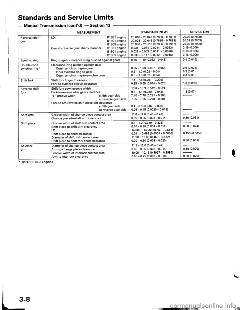
Reverse idlergearl.D. 81881 engineB18C1 engine818C5 engine
Gear-to-reverse gear shaft clearance 81881 engine818C1 engine818C5 engine
20.016 - 20.043 (0.7880 - 0.7891)20.028 - 20.049 (0.7885 - 0.7893)20.030 - 20.1 10 (0.7886 - 0.7917)0.036 - 0.084 (0.0014 - 0.0033)0.028 - 0.053 (0.0011 - 0.0020)0.030 - 0.1 17 (0.0012 - 0.0046)
20.09 (0.7909)
20.09 (0.7909)
20.09 (0.7909)
0.16 (0.006)
0.16 (0.006)
0.16 (0.006)
Synchro ringRing-to-gear clearance (ring pushed against gear)0.85 - 1. t0 (0.033 - 0.043)0.4 (0.016)
Double conesynchro ring *Clearance (ring pushed against gear)
Outer synch ro ring-to-gearInner synchro ring-to-gearOuter synchro ring-to-synch ro cone
0.95 - 1.68 (0.037 - 0.066)0.5 - 1.0 (0.02 - 0.04)0.5 - 1.0 (0.02 - 0.04)
0.6 (0.024)
0.3 (0.01)
0.3 (0.01)
Shift forkShift fork finger thicknessFork-to-synchro sleeve clearance7.4-7.6 (0.291 -0.299)
0.35 - 0.65 (0.014 - 0.026)1.0 (0.039)
Reverse shiftforkShift fork pawl groove widthFork-to-reverse idler gear clearance"L" groove width at Sth gear side . .at reverse gear stdeFork-to-5th/reverse shift piece pin clearanceat 5th gear sideat reverse gear side
13.0 - 13.3 (0.512 - 0.524)0.5-1.1 (0.020-0.043)
7 .40 - 7 .70 (0.291 - 0.303)7 .05 -7.25 (0.278 - 0.285)
0.4 - 0.9 (0.016 - 0.035)0.05 - 0.45 (0.0020 - 0.018)
1.8 (0.07)
Shift armGroove width of change piece contact areaChange piece-to-shift arm clearance
1 1.8 - 12.0 (0.46 - 0.47)0.0s - 0.35 (0.002 - 0.014)oto to.ott t
Shift pieceGroove width of shift arm contact areaShift piece-to-shift arm clearancet.D.Shift piece-to-shaft clearanceDiameter of shift fork contact areaShift oiece-to-shift fork shaft clearance
8.1 - 8.2 (0.319 - 0.323)0.10 - 0.30 (0.004 - 0.012)14.000 - 14.068 (0.551 - 0.554)0.011 - 0.092 (0.0004 - 0.0036)1 1.90 - 12.00 (0.469 - 0.472)0.20 - 0.50 (0.008 - 0.020)
0.60 (0.024)
0.150 (0.0059)
oro to.or'D
SelectorarmDiameter of change piece contact areaArm-to-change piece clearanceGroove width of interlock contact areaArm-to-interlock clearance
1 1.8 - 12.0 (0.46 - 0.47)0.05 - 0.35 (0.002 - 0.014)10.05 - 10.15 (0.3957 - 0.3996)0.05 - 0.25 (0.002 - 0.010)
0.50 (0.0201
0.50 (0.020)
*: 818C1, 818C5 engines
Standards and Service Limits
Manual Transmission (cont'd) - Section 13
t
L
!'lllilil
Page 1654 of 1681
MFASIIREMENTSTANDARD (NEW}
Wire Dia.o.D.Free LengthNo. of Goils
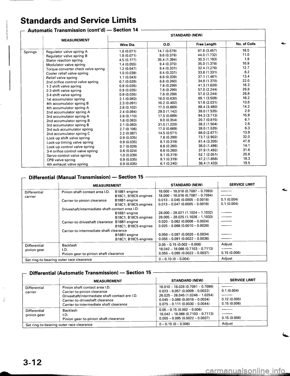
SpringsRegulator valve spring ARegulator valve spring BStator reaction sPringModulator valve springTorque converter check valve springCooler relief valve springRelief valve spring2nd orifice control valve spring1-2 shift valve spring2-3 shift valve spring3-4 shift valve spring1st accumulator spring4th accumulator spring B4th accumulator spring A2nd accumulator spring A3rd accumulator spring A2nd accumulator spring B3rd accumulator spring B3rd sub accumulator spring2nd accumulator spring CLock-up shift valve springLock-up timing valve springLock-up control valve spring3-4 orifice control valve springServo control valve springCPB valve spring4th exhaust valve spring
1.8 (0.071)
1.8 (0.071)
4.5 rc.177].1.4 (0.05s)
1.2 10.047l.1.0 (0.039)
1.1 (0.043)
0.7 (0.0281
0.9 (0.035)
0.9 (0.035)
0.9 (0.035)
2.1 (0.083)
2.3 (0.091)
2.6 (0.102)
2.4 (0.094)
2.8 (0.110)
1.6 (0.063)
2.1 (0.083)
2.7 (0.106)
2.2 l0.o87l0.9 (0.035)
0.9 (0.035)
0.7 (0.028)
0.6 (0.024)
1.0 (0.039)
0.9 (0.0351
0.9 (0.035)
14.7 (0.5791
9.6 (0.378)
35.4 (1 .394)9.4 (0.370)
8.4 (0.331)
8.4 (0.331)
8.6 (0.339)
6.6 (0.260)
7.6 (0.299)
7.6 (0.299)
7.6 (0.299)
16.0 (0.630)
10.2 rc.402117.0 (0.669)
29.0 11.142117.5 (0.689)
9.0 (0.354)
31.0 (1 .220)17.0 (0.669)
14.5 (0.571)
7.6 (0.299)
8.1 (0.319)
6.6 (0.260)
6.6 (0.260)
8.1 (0.319)
8.1 (0.319)
6.1 (0.240)
87.8 (3.457)
44.0 (1.732\
30.3 (1.193)
35.0 (1.378)
32.4 (1.2761.
33.8 (1.331)
37.1 (1.461)
34.8 (1.370)
41.3 (1.626)
57.0 12.244157.0 12.244].89.1 (3.508)
s1.6 (2.0311
88.4 (3.480)
39.0 (1 .53s)94.3 (3.713)
20.7 (0.815)
38.2 (1.504)
39.0 (1.535)
68.0 (2.677)
73.7 (2.9021
81.4 (3.205)
38.0 (1.496)
37.9 (1.492)
52.1 (2.0511
47.2 (1 .858)36.4 (1.433)
16.51 1.01.910.912.78.213.422.01A ?
26.826.8't6.2
13.814.2z.J15.9o. l2.66.313.932.O47.814.1?1 A
20.8ttJ.JI v.5
Standards and Service Limits
Automatic Transmission (cont'd) - Section 14
Differential (Manual Transmission) - Section 15
Differential (Automatic Transmission) - Section 15
ilt5stlrrr, - 4,
MEASUREMENTSTANDARD (NEW}SERVICE LIMIT
Differentialca rnerPinion shaft contact area l.D. 81881 engineB18C1, 818C5 engines
Carrier-to-pinionclearance Bl88lengine818C1, 818C5 enginesDriveshafVintermediate shaft contact area l.D.81881 engine818C1. 818C5 engines
Carrier-to-driveshaft clearance 81881 engine818C1, 818C5 engines
Carrier-to-intermediate shaft clea rance81881 engine818C1, 818C5 engines
18.000 - 18.016 (0.7087 - 0.7093)18.000 - 18.018 (0.7087 - 0.7094)0.013 - 0.045 (0.0005 - 0.0018)0.013 - 0.047 (0.0005 - 0.0019)
28.000 - 28.021 11.1024 - 1.1032].28.005 - 28.025 l1 .'�t026 - 1 .1 033)
0.020 - 0.062 (0.0008 - 0.0024)0.025 - 0.066 (0.0010 - 0.00261
0.050 - 0.087 (0.0020 - 0.0034)0.055 - 0.091 (0.0022 - 0.0036)
- toooot0.1 (0.004)
Differentialpinion gearBacklasht.D.Pinion gear-to-pinion shaft clearance
0.05 - 0.15 (0.002 - 0.006)18.042 - 18.066 (0.7103 - 0.71 1 3)0.055 - 0.095 (0.0022 - 0.0037)
Adjust
0.15 (0.006)
Set ring-to-bearing)uter race clearance0 - 0.10 (0 - 0.004)Adjust
nsmlssaonl - Sectton
MEASUREMENTSERVICE LIMITSTANDARD (NEW}
Differentialca rrierPinion shaft contact area l.D.Carrier-to-pinion clearanceDriveshaft/i ntermediate shaft contact are l.D.
Carrier-to-driveshaft clearanceCarrier-to-intermediate shaft clearance
18.010 - 18.028 (0.7091 - 0.7098)0.023 - 0.057 (0.0009 - 0.0022)26.025 - 26.045 11.0246 - 1.02541
0.045 - 0.086 (0.0018 - 0.0034)0.075 - 0.1 11 (0.0030 - 0.0044)
0.1 (0.004)
0.12 (0.005)
0.15 (0.006)
Differentialpinion gearBacklasht.D.Pinion gear-to-pinion shaft clearance
0.05 - 0.15 (0.002 - 0.006)18.042 - 18.066 (0.7 103 - 0.71 1 3)0.055 - 0.095 (0.0022 - 0.0037)0.15 (0.006)
Set ring-to-bearing outer race clearance0 - 0.15 (0 - 0.006)Adiust
uL-
3-12
(-
Page 1655 of 1681
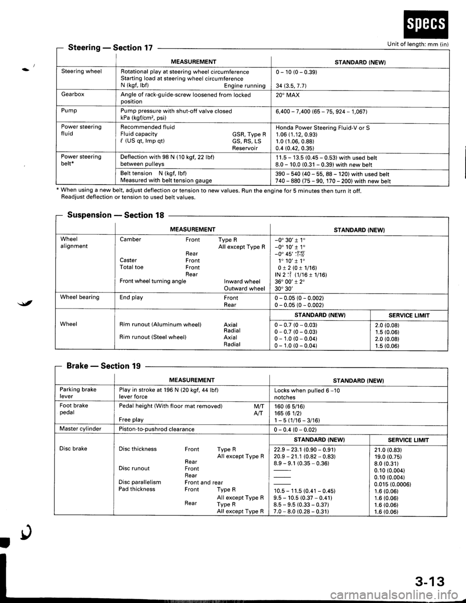
MEASUREMENTSTANDARD (NEWI
Steering wheelRotational play at steering wheel circumferenceStarting load at steering wheel circumferenceN (kgf, lbf) Engine running
0 - 10 (0 - 0.39)
34 (3.5,7 .71
GearboxAngle of rack-guide-screw loosened from lockedoosition20'MAX
PumpPump pressure with shut-off valve closedkPa (kgf/cm,, psi)6,400 - 7,400 (65 - 75, 924 - 1,067],
Power steeringfluidRecommended fluidFluid capacity GSR, Type Rf (US qt, lmp qtl cS, RS, LSReservoir
Honda Power Steering Fluid-V or S1.06 (1.12,0.93)
1.0 (1.06,0.88)
0.4 (0.42, 0.35)
Power steeringbelt*Deflection with 98 N (10 kgf,22 lbflbetween pulleys1 1.5 - 13.5 (0.45 - 0.531 with used belt8.0 - 10.0 (0.31 - 0.39) with new belt
Belt tension N (kgf, lbf)Measured with belt tension gauge390 - 540 (40 - 55, 88 - 120) with used belt740 - 880 (75 - 90, 170 - 2001with new belt
SteeringSection 17
* When using a new belt, adjust deflection or tension to new values. Run the engine for 5 minutes then turn it off.Readiust deflection or tension to used belt values.
Suspension - Section 18
BrakeSection 19
Unit of length: mm (in)
$t
MEASUREMENTSTANDARD (NEWI
WheelalignmentCamber Front Type RAll except Type RRearCaster FrontTotal toe FrontRearFront wheel turning angle Inward wheelOutward wheel
-0'30'r 1"-0' 10'r 1.-0" 45'�1?:i3i1. 10'�1 1.0!210!1116!,lN 2 lf (t7t6 1 1716136. 00'1 2"30'30'
Wheel bearingEnd play FrontRear0 - 0.05 (0 - 0.002)0 - 0.05 (0 - 0.002)
WheelRim runout (Aluminum wheel) AxialRadialRim runout (Steel wheel) AxialRadial
STANDARD (NEW}SERVICE LIMIT
0 - 0.7 (0 - 0.03)0 - 0.7 (0 - 0.03)0 - 1.0 (0 - 0.04)0 - 1.0 (0 - 0.04)
2.0 (0.08)
1.5 (0.06)2.0 (0.08)1.5 (0.06)
MEASUREMENTSTANDARD (NEW}
Parking brakeleverPlay in stroke at 196 N (20 kgf,44 lbf)lever forceLocks when oulled 6 -10
notches
Foot brakepedalPedal height (With floor mat removed)
Free play
M/TAtT160 (6 5/161165 rc 1nl1-5(1/16-3/16)
Master cylinderPiston-to-oushrod clearance0 - 0.4 (0 - 0.021
Disc brakeDisc thickness Front Type RAll except Type RRearDisc runout FrontRearDisc parallelism Front and rearPad thickness Front Type R
All except Type RRear Type RAll except Type R
STANDARD (NEWISERV]CE LIMIT
22.9 - 23.1 (0.90 - 0.91120.9 - 21.1 (0.82 - 0.83)
1= t (0.35-0.361
10.5 - 11.5 (0.41 - 0.45)9.5 - 10.5 (0.37 * 0.41)8.5 - 9.5 (0.33 - 0.37)7.0 - 8.0 (0.28 - 0.31)
21.0 (0.83)19.0 (0.75)
8.0 (0.31)
0.10 (0.004)
0.10 (0.004)
0.015 (0.0006)1.6 (0.06)
1.6 (0.06)1.6 (0.06)
1.6 (0.06)
Page 1657 of 1681
{b
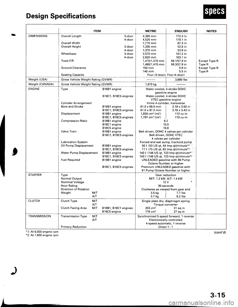
Design Specifications
x1: At 6,000 engine rpm*2: At 7,600 engine rpm
0
(cont'd)
{
ITEMMETRICENGLISHNOTES
DIMENSIONSOverall Length 3-door4-doorOverall WidthOverall Height 3-door4-doorWheelbase 3-door4-doorTrack F/R
Ground Clearance
Seating Capacity
4,380 mm4,525 mm1,710 mm1,335 mm ]1,370 mm ]2,57O mm2,62O mm 11 ,415/1,470 mm I1,480/1,470 mm I1s0 mm I140 mm IFour (3-door),
172.4 in178.1 in67.3 in52.6 in53.9 in101.2 in103.1 in58.1/57.9 in58.3/57.9 in5.9 in5.5 tnFive (4-door)
Except Type RType RExcept Type RType R
weisht (usA)Gross Vehicle Weight Rating (GVWR)3.680 rbs
Weight (CANADA)Gross Vehicle Weight Rating (GVWR)1,670 kg
ENGINEType
Cylinder ArrangementBore and Stroke
Displacement
Compression Ratio
Valve Train
Lubrication SystemOil Pump Displacement
Water Pump Displacemenl
Fuel Required
8188l engine
818C1, Bl8C5 engines
81881 engine818C1, 818C5 engines81881 engine818C1, B18C5 engines81881 engine818C1 engine818C5 engineB1881 engine818C1, B18C5 engines
81881 engine818C1, B18CS enginesB1881 engine818C1, 818C5 enginesB1881 engine
818C1,818C5 engines
Water-cooled. 4-stroke DOHCgasoline engineWater-cooled, 4-stroke DOHCVTEC gasoline engineInline 4-cylinder, transverse81.0 x 89.0 mm | 3.19 x 3.50 in81.0 x 87.2 mm | 3.19 x 3.43 in1,834 cm3 (m/ ) | 112 cu-in1,797 cm3 (m/ ) | 110 cu-in9.210.010.6Belt driven, DOHC 4 valves per cylinderBelt driven, DOHC VTEC4 valves per cylinderForced and wet sump, trochoid pump50 f (53 US qt, 44 lmp qt)/minute*'71 ( (75 US qt,62 lmp qt)/minute*'� :
140 I 1148 US qt. 123 lmp qtl/minute*1140 t (148 US qt, 123 lmp qt)/minute*2UNLEADED gasoline with 86 PumpOctane Number or higherPremium UNLEADED gasoline with91 Pump Octane Number or higher
STARTERTypeNormal OutputNominal VoltageHour RatingDirection of RotationWeight MffAIT
Gear reductionMfi:1.2 kW, A,/T: 1.4 kW12V ,
30 secondsClockwise as viewed from gear end3.5 ks | 7.7 lbs3.7 kg | 8.2 lbs
CLUTCHClutch Type
Clutch Facing Area
M/TAfiM/T 81881, 818C1 engines818C5 engine
Single plate dry, diaphragm springTorque converter203 cm2 , 31 sq-in176 cm2 | 27 sq-in
TRANSMISSIONTransmission Type
Primary Reduction
M/TAITSynchronized S-speed forward, 1 reverseElectronical ly control led4-speed automatic, 1 reverseDirect 1 : 1
3-15
Page 1658 of 1681
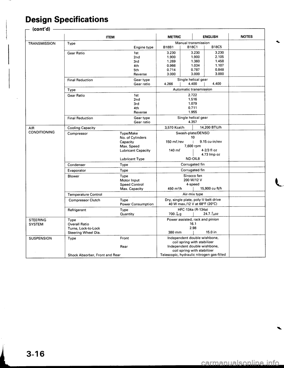
ITEMMETRICIENGLISHINOTES
TRANSMISSIONTypeEngine typeManual transmissionB18B1lB18C1lB18C5
Gear Ratio1st2nd3rd4th5thReverse
3.230't.900
1.2690.9660.7143.000
3.2301.9001.3601.0340.7873.000
3.2302.1051.4581.1070.8483.000
Final Reduction Gear typeGear ratioSingle helical gear4.266 14.400 14.400
TypeAutomatic transmission
Gear Ratio 1st2nd3rd4thReverse
2.722't.516
1.0790.7111.955
Final Reduction GeartypeGear ratioSingle helical gear4.357
AIRCONDITIONINGCooling Capacity3.570 Kcar/h | 14,200 BTU/h
Compressor Type/MakeNo. of CylindersCapacityMax. SpeedLubricant Capacity
Lubricant Type
Swash-plate/DENSO10150 m//rev | 9.15 cu-in/rev7,600 rpm140 m/ | 4-213 fl oz
I c.z3 |rp o.ND.OILS
Condenser TypeCorrugated fin
Evaporator TypeCorrugated fin
Blower TypeMotor InputSpeed ControlMax. Capacity
Sirocco fan200w1't2v4-speed450 m3/h | 15,900 cu fVh
Temperature ControlAir-mix type
Compressor Clutch TypePower ConsumptionDry. single plate, poly-V-belt drive40W max.l12 V at 68'F (20'C)
Refrigerant TypeQuantityHFC-134a (R-134a)
700_309 | 24.7_?.aoz
STEERINGSYSTEMTypeOverall RatioTurns, Lock-to-LockSteering Wheel Dia.
Power assisted, rack and pinion16.12.98380 mm | 15.0 in
SUSPENSIONType Front
Rear
Shock Absorber, Front and Rear
Independent double wishbone,coil spring with stabilizerIndependent double wishbone,coil spring with stabilizerTelescopic, hydraulic nitrogen gas-filled
Design Specifications
(cont'd)
L
\
Page 1664 of 1681
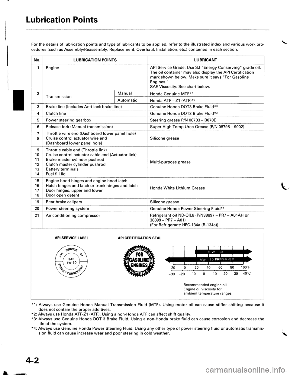
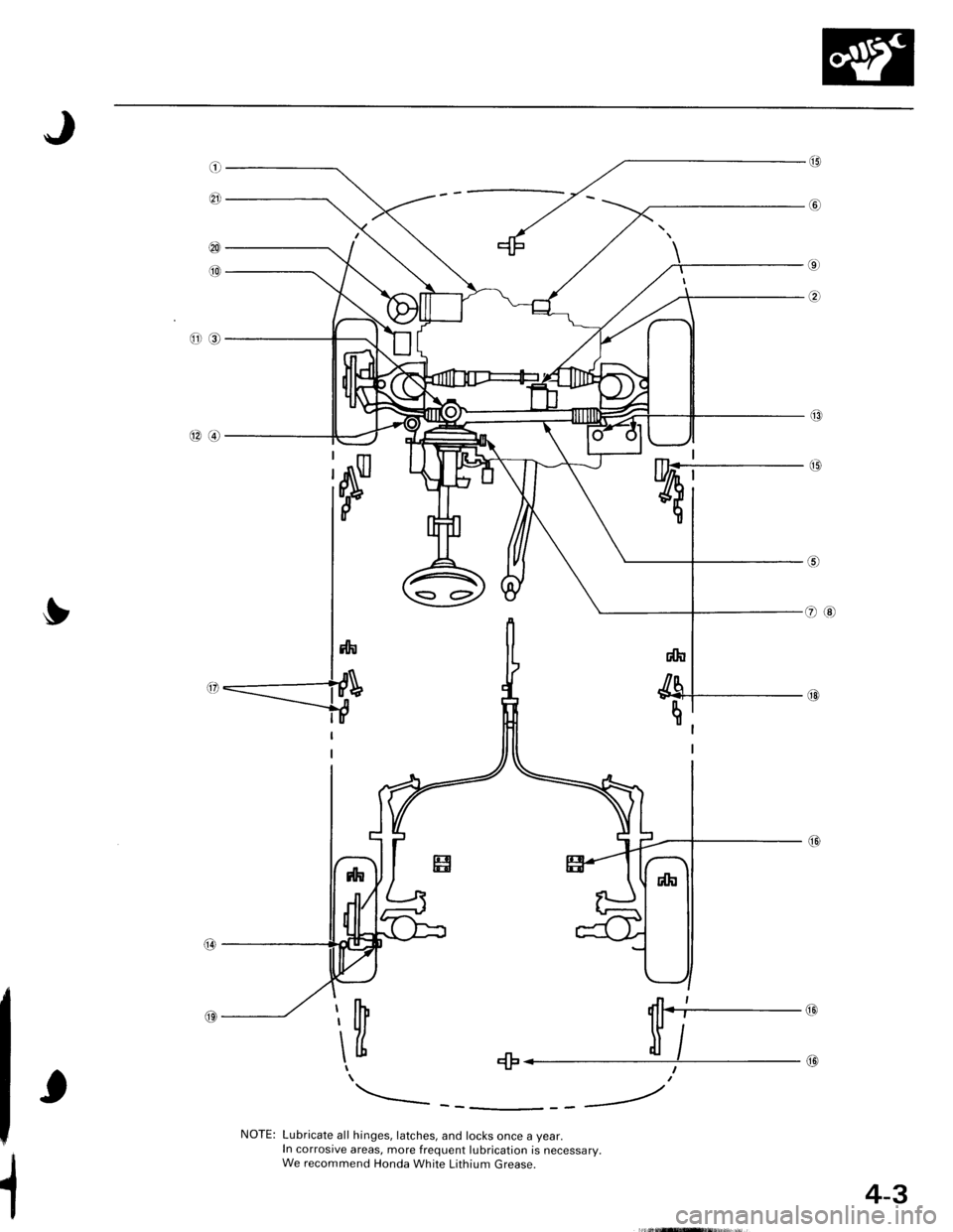
Lubrication Points
\_For the details of lubrication points and type of lubricants to be applied, refer to the illustrated index and various work pro-
cedures (such as Assembly/Reassembly, Replacement, Overhaul, Installation, etc.) contained in each section.
*1: Always use Genuine Honda Manual Transmission Fluid (MTF). Using motor oil can cause stiffer shifting because it
does not contain the proper additives.*2: Always use Honda ATF-Z1 (ATF). Using a non-Honda ATF can affect shift quality.*3: Always use Genuine Honda DOT 3 Brake Fluid. Using a non-Honda brake fluid can cause corrosion and decrease thelife of the system.*4: Always use Genuine Honda Power Steering Fluid. Using any other type of power steering fluid or automatic transmis-sion fluid can cause increase wear and poor steering in cold weather.i
4-2
5 ffi
No.LUBRICATION POINTSLUBRICANT
1EngineAPI Service Grade: Use SJ "Energy Conserving" grade oil.The oil container may also display the API Certificationmark shown below. Make sure it says "For GasolineEngines."
SAE Viscosity: See chart below.
2Tra.nsmissionManualHonda Genuine MTF*2
AutomaticHonda ATF -21 (ATFY2
3Brake line (lncludes Anti-lock brake line)Genuine Honda DOT3 Brake Fluid*3
4Clutch lineGenuine Honda DOT3 Brake Fluid*3
5Power steering gearboxSteering grease P/N 08733 - 8070E
6Release fork (Manual transmission)Super High Temp Urea Grease (P/N 08798 - 9002)
.J
Throttle wire end (Dashboard lower panel hole)
Cruise control actuator wire end(Dashboard lower panel hole)
Silicone grease
q
10
11
12
13
14
Throttle cable end (Throttle link)
Cruise control actuator cable end (Actuator link)Brake master cylinder pushrod
Clutch master cylinder pushrod
Battery terminalsFuel fill lid
Multi-purpose grease
tc
16
17
18
Engine hood hinges and engine hood latchHatch hinges and latch or trunk hinges and latch
Door hinges, upper and lower
Door open detent
Honda White Lithium Grease
19Rear brake calipersSilicone grease
20Power steering systemGenuine Honda Power Steering Fluid*a
21Air conditioning compressorRefrigerant oil ND-olL8 (P/N38897 - PR7 - A01AH or
38899-PR7-A01)(For Refrigerant: HFC-1 34a (R-1 34a))
API SERVICE TABELAPI CERTIFICATION SEAT
ZU30
Recommended engine oilEngine oil viscosity forambient temperature ranges
Page 1665 of 1681
e
@
€E
@
\[+. il/ tI
NOTE: Lubricate all hinges, latches, and locks once a year.In corrosive areas, more frequent lubrication is necessary.We recommend Honda White Lithium Grease.
{4-3
Page 1671 of 1681
Radiator
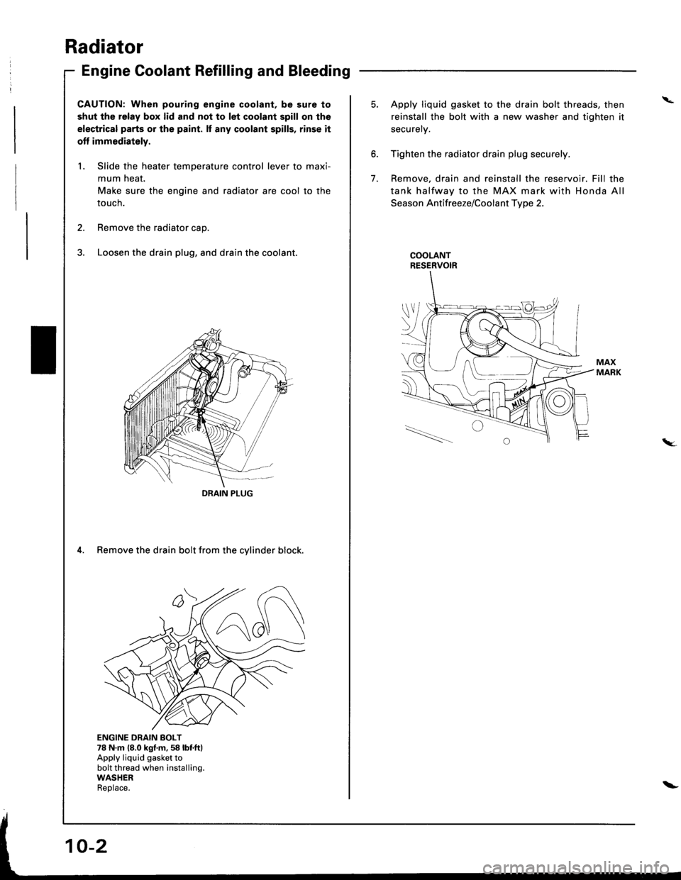
Engine Goolant Refilling and Bleeding
CAUTION: When pouring engine coolant, be sure to
shut the relay box lid and not to let coolant spill on the
electrical parts or the paint. lf any coolant spills, rinse it
off immediately.
1. Slide the heater temperature control lever to maxi-
mum heat.
Make sure the engine and radiator are cool to the
touch.
2. Remove the radiator caD.
3. Loosen the drain plug, and drain the coolant.
4. Remove the drain bolt from the cylinder block.
ENGINE DRAIN BOLT78 N.m (8.0 kgf.m,58 lbf.ftlApply liquid gasket tobolt thread when installing.WASHERReolace.
DRAIN PIUG
I \.--
\_-l - I
\
6.
7.
5. Apply liquid gasket to the drain bolt threads, then
reinstall the bolt with a new washer and tighten it
securely.
Tighten the radiator drain plug securely.
Remove, drain and reinstall the reservoir. Fill the
tank halfway to the MAX mark with Honda All
Season Antifreeze/Coolant Type 2.
COOLANTRESERVOIR
tW.
\-