spark plugs HONDA INTEGRA 1998 4.G Workshop Manual
[x] Cancel search | Manufacturer: HONDA, Model Year: 1998, Model line: INTEGRA, Model: HONDA INTEGRA 1998 4.GPages: 1681, PDF Size: 54.22 MB
Page 316 of 1681

ldle Speed Setting
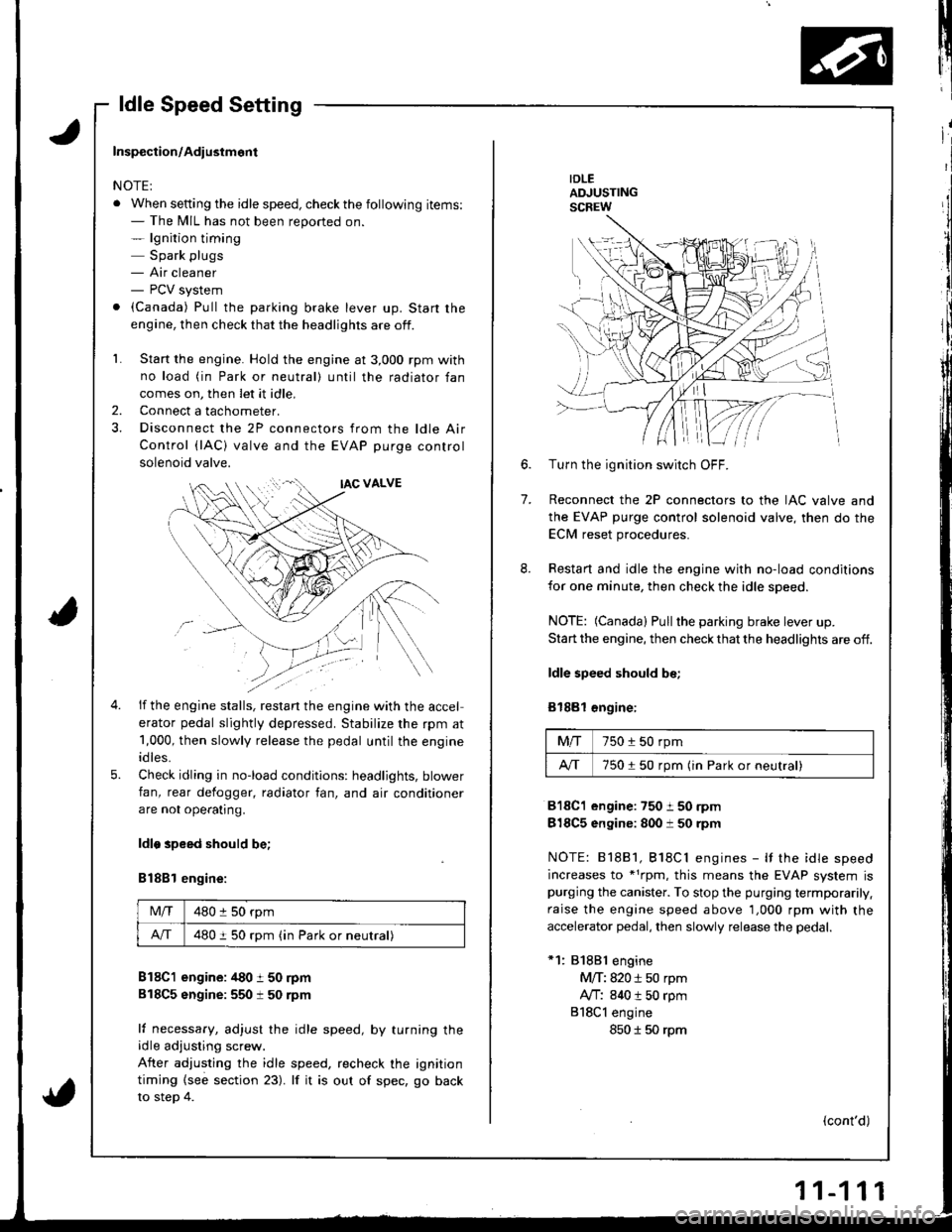
IDLEADJUSTINGSCREW
7.
6.Turn the ignition switch OFF.
Reconnect the 2P connectors to the IAC valve and
the EVAP purge control solenoid valve, then do the
ECM reset procedures.
Restart and idle the engine with no-load conditions
for one minute, then check the idle speed.
NOTE: (Canada) Pullthe parking brake lever up.
Start the engine, then check that the headlights are off.
ldle speed should be;
Bl88l €ngine:
Mfi750 i 50 rpm
A/T750150 rpm (in Park or neutral)
818C1 engine:750 i 50 rpm
818C5 engine: 800 i 50 rpm
NOTE: 81881, Bl8Cl engines - It the idle speed
increases to *1rpm, this means the EVAP system ispurging the canister. To stop the purging termporarily.
raise the engine speed above 1,000 rpm with the
accelerator pedal, then slowly release the pedal.
*1: 81881 engine
M/T: 820 i 50 rpm
Ay'T: 840 t 50 rpm
818Cl engine
850 I 50 rpm
(cont'd)
Inspection/Adiustmont
NOTE:
. When setting the idle speed, checkthe following items:- The MIL has not been reported on.- lgnition timing
Spark plugs- Air cleaner- PCV system
. (Canada) Pull the parking brake lever up. Start the
engine, then check that the headlights are off.
1. Start the engine. Hold the engine at 3,000 rpm with
no load (in Park or neutral) until the radiator fan
comes on, then let it idle,
Connect a tachometer.
Disconnect the 2P connectors from the ldle Air
Control (lAC) valve and the EVAP purge control
solenoid valve.
2.
5.
if the engine stalls, restan the engine with the accel
erator pedal slightly depressed. Stabilize the rpm at
1,000, then slowly release the pedal until the engine
idles.
Check idling in no-load conditions: headlights, blower
fan, rear defogger, radiator fan, and air conditioner
are not ope€tlng.
ldlo speed should be;
B188l engine:
Mlf480 :l 50 rpm
A/T480 i 50 rpm (in Park or neutral)
B18C1 engine: /t80 t 50 rpm
818C5 sngine:550 t 50 rpm
lf necessary, adjust the idle speed, by turning theidle adjusting screw.
After adjusting the idle speed, recheck the ignition
timing {see section 23). lf it is out of spec, go back
to steo 4.
Page 1058 of 1681

J
Electrical
Speciaf Toofs ..........................23-2
Troubleshooting
Tips 8nd Precautions .......................,..,.,.,.,.,......,..., 23-3
Five-step Troubleshooting ............,......,.,.,...,..,....., 23-5
Schsmatic Svmbols ...............23-6
Wire Color Code3 .. ................. 23-6
Relay and Control Unit Locations
Engine Compartment ......,.,.................,.,.,.,.,.,,,, 23-7
Dashboard and Door .........,...........,.....,.,....,.,.... 23-8
Dashboard and Floor ......................................... 23-10
Ouarter Pan€f .,,.,...,.,..,...,,,23-12
Connector ldontification and WireHarness Routing ......,.,......23-'13
Index to Circuits and Systems
Airbag
* Integrated Control Unit .....,.,.,.....23-152* Interlock Sytem .,...,.,...........,. 23.146
Lights, Exterior
Eack-up LighB ..................23.187
Brake Ligh$ ......................23-190*Daytime Running Lights (Canada) ................... 23"164
Front Parking Lights .......................................... 23-173
Front Side Marker Lights .................................. 23-173
Front Turn Signal Lights ..................-.......,...,.,. 23-173* Hazard Warning Lights ....................,........,....... 23-192
Headlights.....23-169
23-253 powerDistribution..................... 23-5/r
Air Conditioning.....,....... Soction 21
Alternator ..........,................... 23.99
iCigarette Lighter .........23-212
*Cruise Control
Distributor
'.'.,.'.'.,.'...,,,,.,''.'.,.',.'''.' 23.277
.............................. 23.88
................... 23-90lgnition Timing ......
Indicator Lights
Key-in Reminder System
Maintenance Reminder System*Seat Belt R€mindor System .,...........................* Side Marker/Turn Signal/HazardFlashcr Svstem .................23-192
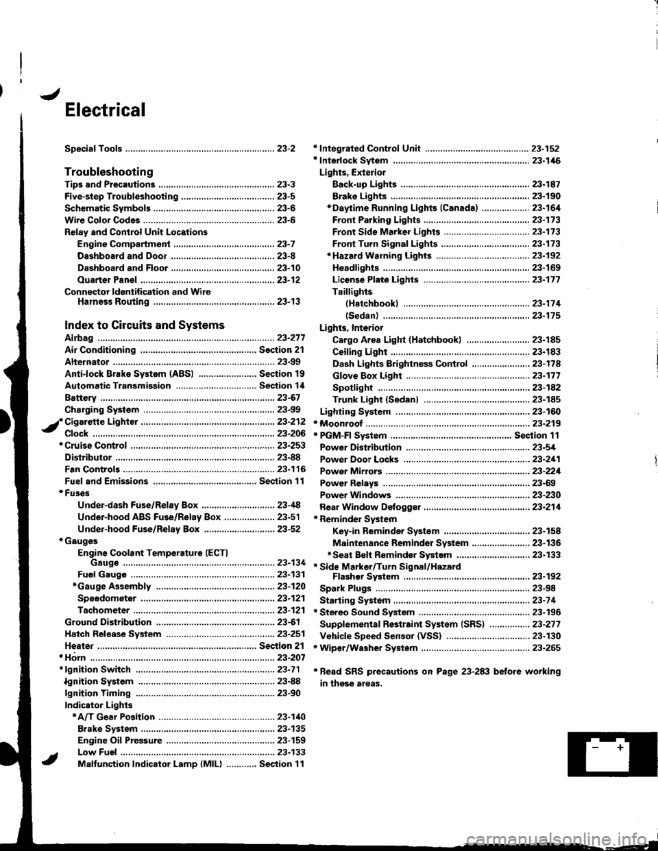
Spark Plugs ............................23-98
Starting System .....................23-74* Stereo Sound System ...,......,..........,...,......,.,.,.,..,., 23-196
Supplemental Restraint System (SRS) ................ 23-277
Vshicle Speed Sensor (VSS) ................................. 23.130r Wiper/Washer System .........................................., 23-265
*Read SRS precautions on Psge 23-283 before working
in those areas,
23-154
23.136
23"133
Page 1155 of 1681

lgnition System
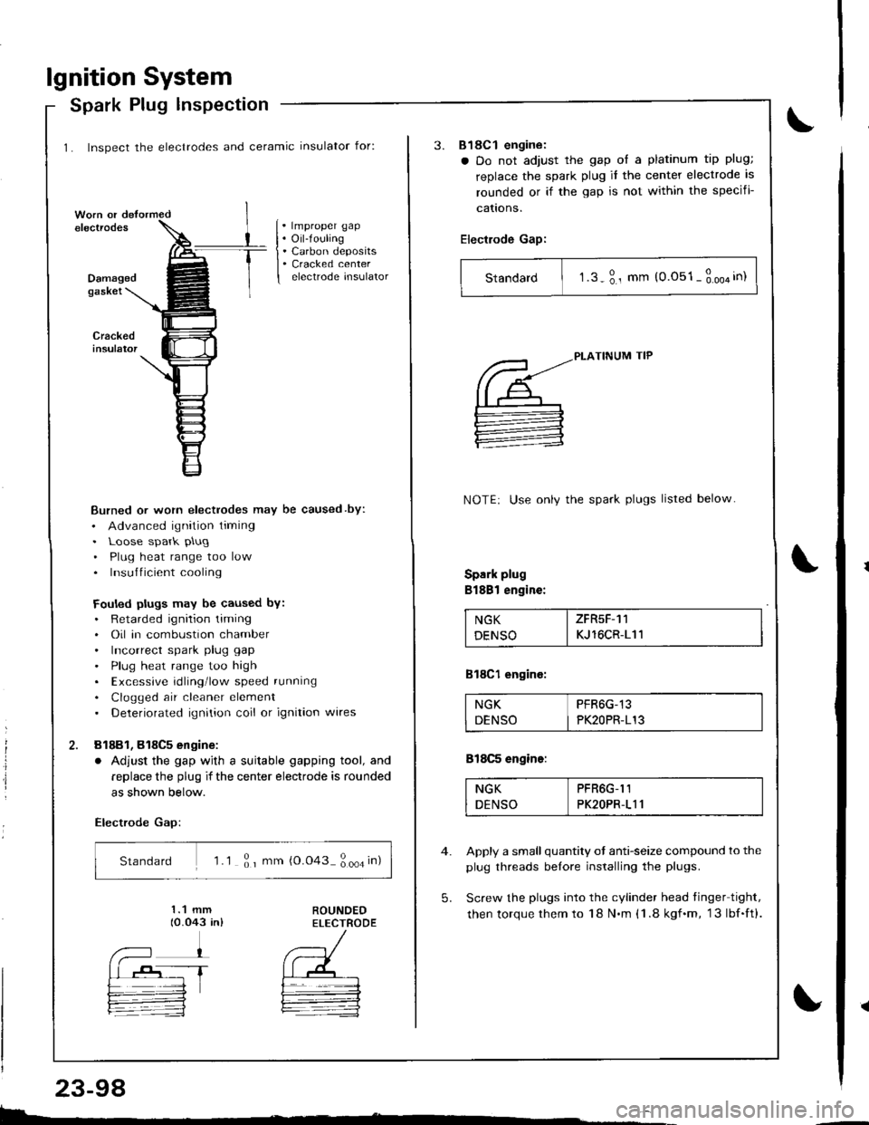
1. Inspect the electrodes and ceramic insulator for:
Spark Plug lnspection
. lmproper gap. Oil-fouling. Carbon deposits. Cracked centerelectrode insulatorDamagedgaskei
Burned or worn electrodes may be caused by:
. Advanced ignition timing. Loose spark plug
. Plug heat range too low. Insufficient cooling
Fouled plugs may be caused bY:. Retarded ignition liming. Oil in combustion chamber. Incorrect spark plug gap
. Plug heat range too high. Excessive rdling'low speed running
. Clogged air cleaner element. Deteriorated ignition coil or ignition wires
81881, 818C5 engine:
. Adjust the gap wjth a suitable gapping tool, and
replace the plug if the center electrode is rounded
as shown below.
Electrode Gap:
Standard 'l .1 ; r mm {0.043 ; ooa in)
E.
23-98
3.818C1 engine:
a Do not adjust the gap ol a platinum tip plug;
replace the spark plug it the center electrode is
rounded or if the gap is not within the specifi-
cattons.
Electrode Gap:
Standard I t.s-3., mm (0.051-3.oo4in)
5.
PLATINUM TIP
NOTE: Use onlv the spark plugs listed below
Spark plug
Bl88l engine:
NGK I ZFR5F-11
DENSO I KJ 16CR-111
818C1 engine:
NGK PFR6G-13
DENSO I PK2OPR-113
818C5 engine:
NGK PFR6G-I1
DENSO PK2OPR-111
Apply a small quantity ot anti-seize compound to the
plug threads belore installing the plugs.
Screw the plugs into the cylinder head tinger tight,
then torque them to 18 N.m (1 .8 kgf.m, 13lbf.ft).
Page 1429 of 1681

lgnition System
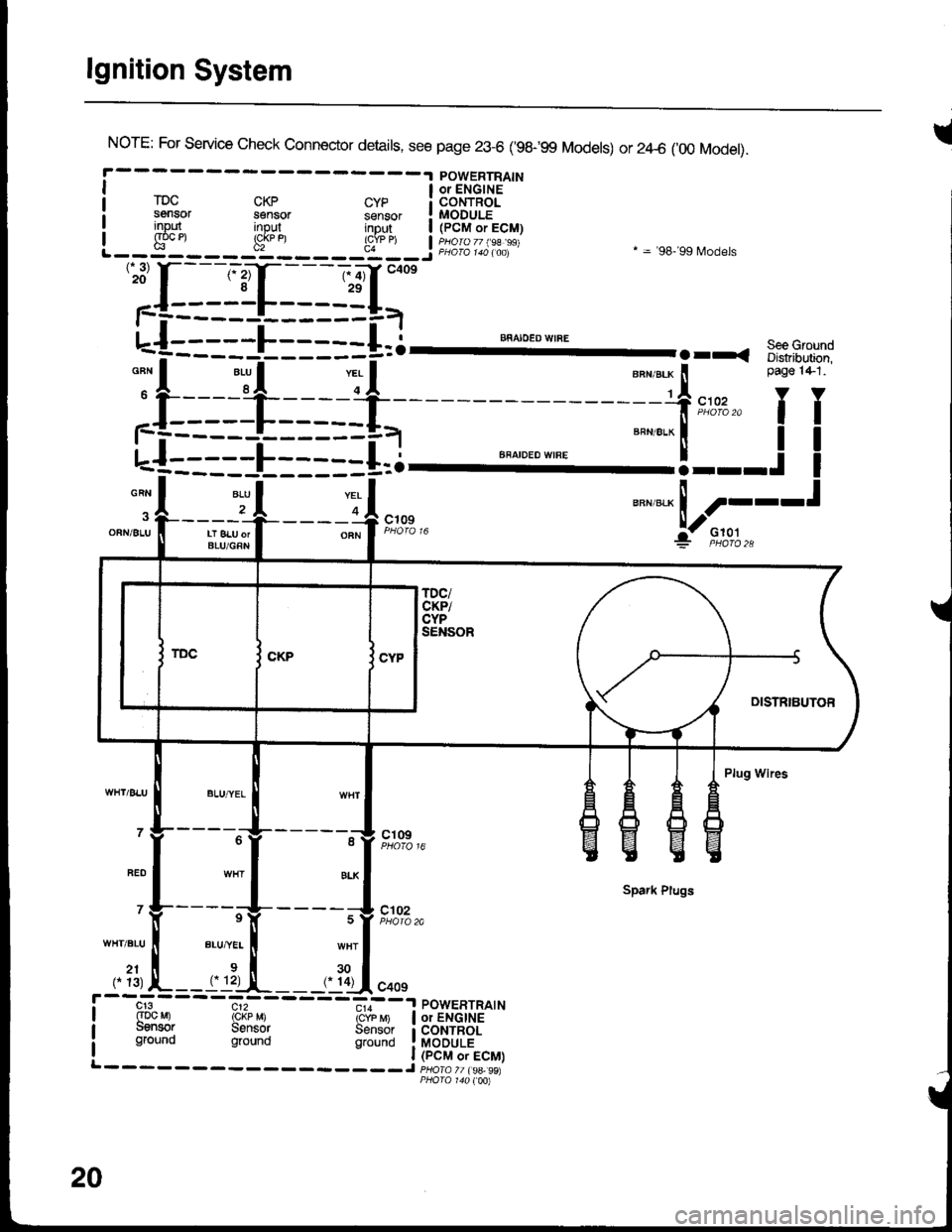
INorE: For service check connector details, see page 23-6 ('98-99 Models) or 2zl-6 ('00 Model).
POWERTRAINI a oielcirs '-"
rDc cKp cyp i coNTRoLsensor sensor sensor ! MODULEinout inout intu,t | /PCM.ri! input input inDut | (pCM or ECM)I g"oc et !cj
u"n,"." ! ----t
:jl--Jt---r-4,*"
"""*-Lf;
'':[:-==1-I=-==g=,-
u-{:::::L:::::+=i--- ""^".:-I'
.rr. s::3-.-:
;f:===-l_=* -=-f,*,,'fT
L-f--====E=--==i.l ""'"'"*'"'
=="=-'!---.!
I
-A 2r .|--___-OFNi 8LU II LT 8LU orI BLU/GRN
----o A c';;? F;o''","i:- F,to,l.,
Plug Wires
- - - -"-'lg- - - - - -^11 ct og
Spark Plugs
' Y-----rV-
- - - - ;V t#'",.
WHT.BLU ll BLU,"YEL I wHT
,. ?1, L--rrl:-,!-__,. ?Ll.oo,
cr3 c12 - - -.,,--a POWERTRATN(Dc Mr rckp M) icrb 6 | or ENGINEuensor Sensor Sensor i coNTRoLground ground grouno !laODuLi
20