fuse box HONDA INTEGRA 1998 4.G Owner's Guide
[x] Cancel search | Manufacturer: HONDA, Model Year: 1998, Model line: INTEGRA, Model: HONDA INTEGRA 1998 4.GPages: 1681, PDF Size: 54.22 MB
Page 809 of 1681
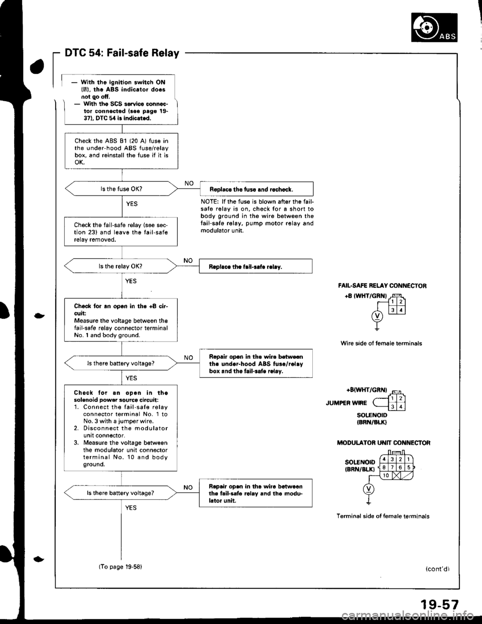
DTC 54: Fail-safe Relay
- With tho ignition switch ONlll), the ABs indicato. do.snol qo oft.- lr
ith tho SCS sorvico oonncc-tor connoctod (aoe pago 19-37). DTC 5,1 i3 indicli.d.
NOTE: lf the fuse is blown after the fail-sato relay is on. check for a short tobody ground in the wire between thetail-saf6 relay, pump motor relay andmodulator unit.
-
FAIL.SAFE RELAY CONN€CTON
+8 IWHT/GRNI J-F1r- l l2l
EIN(v) -
Y
Wire sade ol female terminals
+8{WHT/GRN| '.5
JUMPEFWIFE ( ffi-----1113
soltNorD{BRN/BLK}
MODULATOR UN]T CON ECTOR
sot"ENorD{BRN/BLKI
Terminal side ot female terminals
Check the ABS 81 (20 A) fuse inthe under'hood ABS fuse/relaybox, and reinstall the luse if it isoK.
R.olaco tho fu3! .nd rochocl.
Check the fail-safe relay (see sec-tion 23) and leavo tho tail-saferetay removed.
Chock lor an opan in th6 +8 cir-cuit:Measure the voltage between th€fail-safe relay connector terminalNo. 1 and body ground.
Ropair opon in tha wire botwecnths undor-hood ABS fuso/rol.ybox.nd ihe tail.3at r.lay,
ls there battery voltage?
Chock tor.n op6n in thesolenoid power 3ourco circuit:1. Connect the fail'saIe relayconnector terminal No. 1 toNo. 3 with a jumper wire.2. Disconnect the modulatorunit connector,3. Measure tho voltage betweenthe modulator unit connectorterminal No. 10 and bodyground.
Rep.ir open in tha wira betwoonthe fril-rete rolay and tha modu-lator unit.
ls there battery voltage?
(To page 19-58)(cont'dl
Page 949 of 1681
Dashboard
Component Removal/lnstallation (cont'dl
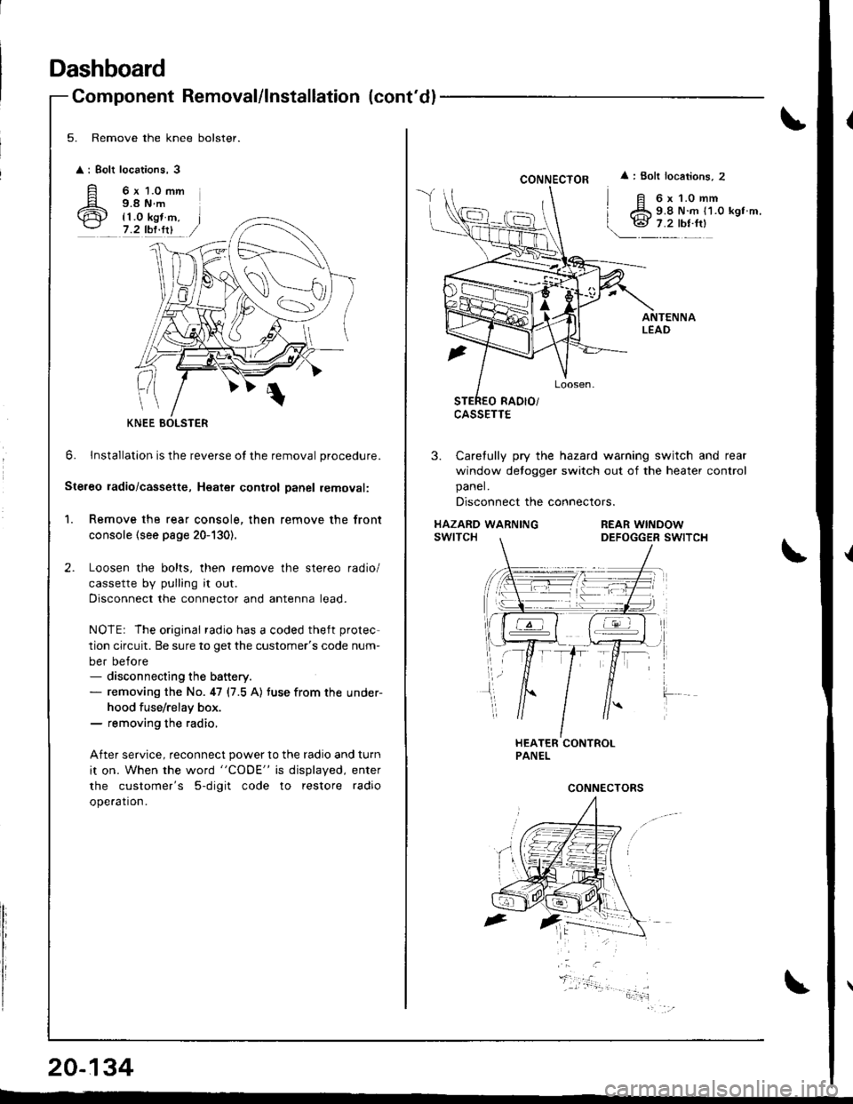
5. Remove the knee bolster.
: Bolt
A'ir
locations,3
6 x 1.0 mm9.8 N.m
{1.0 kgt m,7.2 tbf.fit
0
6. lnstallation is the reverse o{ the removal procedure.
Ste.eo ladio/cassette, Heatet contlol Danel removal:
1. Remove the rear console, then remove the front
console (see page 20-130).
Loosen the bolts, then remove the stereo radio/
cassette by pulling it out.
Disconnect the connector and antenna lead.
NOTEr The original radio has a coded theft protec-
tion circuit. Be sure to get the customer's code num-
ber before- disconnecting the battery.- removing the No. 47 (7.5 A) tuse from the under-
hood fuse/relay box.- removing the radio,
After service, reconnect power to the radio and turn
it on. When the word "CODE" is displayed, enter
the customer's 5-digit code to restore radio
ope.ation.
KNEE BOLSTER
20-134
CONNECTOR
CASSETTE
: Bolt locations, 2
6x1.0mm9.8 N.m {1.0 kgt m,
3. Carefully pry the hazard warning switch and rear
window detogger switch out of the heater control
panel.
Disconnect the connectors.
HAZARD WARNINGswtTcHREAR WINDOWDEFOGGER SWITCH
CONNECTORS
Page 953 of 1681
Dashboard
Replacement Precautions
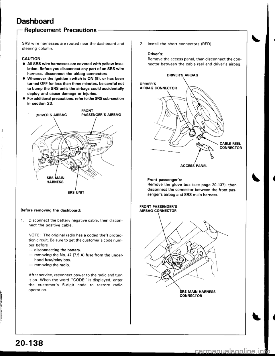
SRS wire harnesses are routed near the dashboard and
steenng column.
CAUTION:
a All SRS wire hsrnesses are covered wiih yellow insu-
lation. Before you disconnect any pan of an SRS wire
harness, disconnect the airbag conneclors.
a Whenever the ignition switch is ON (ll), or has been
tulned OFF for less than three minules, be careful not
to bump the SRS unit; the ai.bags could accidentally
deploy and cause damage or injuries.
a For additional precautions, refer lo the SRS sub-section
in section 23.
PASSENGER'S AIRBAG
Belore removing the dashboard:
1. Disconnect the battery negative cable, then discon-ne.r rhe n^.iriua.ahla
NOTEr The original radio has a coded thett protec,
tion circuit. Be sure to get the customer's code num
ber before- disconnecting the battery.- removing the No. 47 (7.5 A) fuse from the under-
hood tuse/relay box.- removing the radio.
After service, reconnect power to the radio and turn
it on. When the word "CODE" is displayed, enter
the customer's 5-digit code to restore radio
operation.
DRIVER'S AIRBAG
SRS UNIT
20-138
2.Install the short connectors (RED).
Driver's:
Remove the access panel, then disconnect the con-
nector between the cable reel and driver's airbag.
CABL€ REELCONNECTOR--_--._-_-----
Front passenger's:
Remove the glove box (see page 20-137), thendisconnect the connector between the front pas-
senger's airbag and SRS main harness.
FRONT PASSENGER'SAIRBAG CONNECTOR
SRS MAIN HARNESSCONNECTOR
ORIVER'S AIRBAG
Page 955 of 1681
Dashboard
6.
Replacement (cont'dl
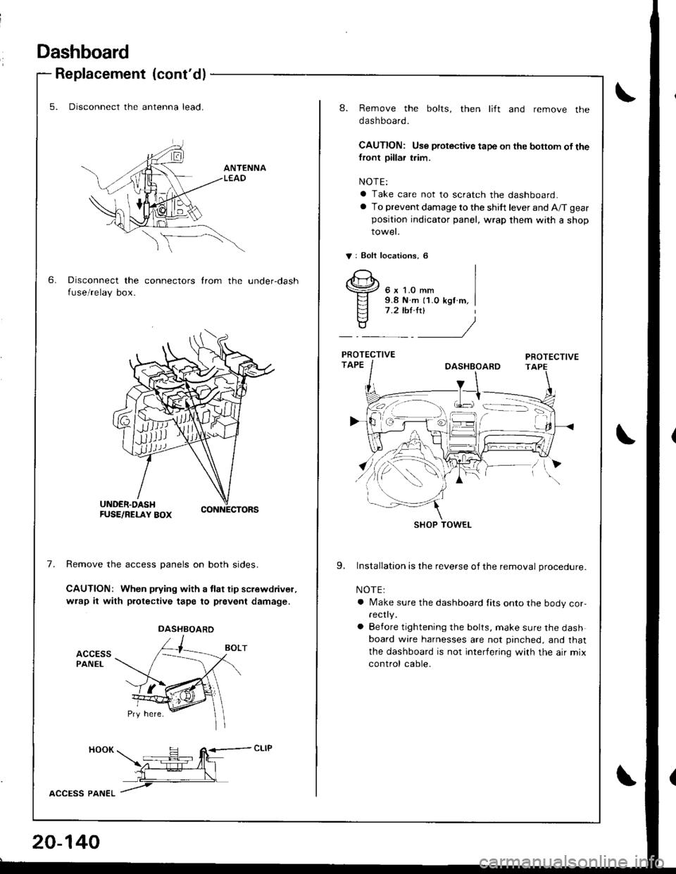
5. Disconnect the antenna lead.
Disconnect the connectors from the under-dash
fuse/relay box.
7.Remove the access panels on both sides.
CAUTION: When pfying with a tlat tip screwdrivel,
wrap it with protective tape to prevent damage.
ACCESSPANEL
HOOK H R<-- cLlP -- tfit\z-:E--4l_l
L__\L
lccPss pltlteL /
DASHBOARD
20-140
8. Remove the bolts, then lift and remove the
dashboard.
CAUTION: Use protective tape on the bottom of thefront pillar trim.
NOTE:
a Take care not to scratch the dashboard.
a To prevent damage to the shift lever and A/T gear
position indicator panel, wrap them with a shop
rowet.
V: Eolt localions, 6
6 x 1.0 mm9.8 N.m {1.0 kgf m,7 .2 ,hl.ltl
9. Installation is the reverse of the removal procedure.
NOTE:
a Make sure the dashboard fits onto the body cor,rec y.
a Before tightening the bolts, make sure the dashboard wire harnesses are not pinched, and that
the dashboard is not interfering with the air mix
control cable.
SHOP TOWEL
Page 993 of 1681
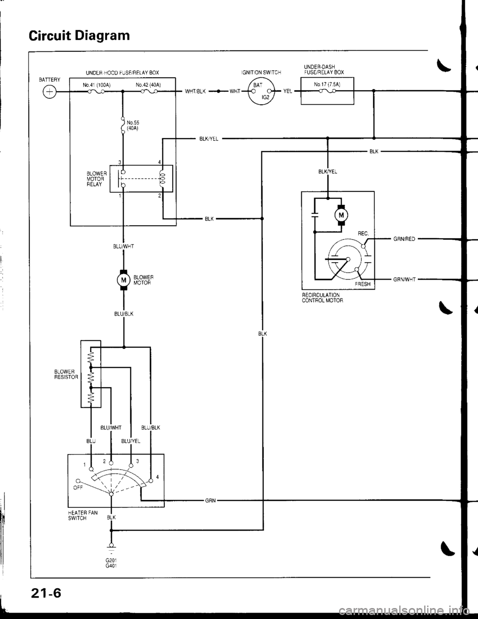
Circuit Diagram
R€CIRCULATIONcoNTROt MOTOR
UNDER HOOD FUSE/RELAY BOX
N0.41 (1004) N0.42 (40A)
,,\J.orr --'-- l,--
BtK
21-6
Page 998 of 1681
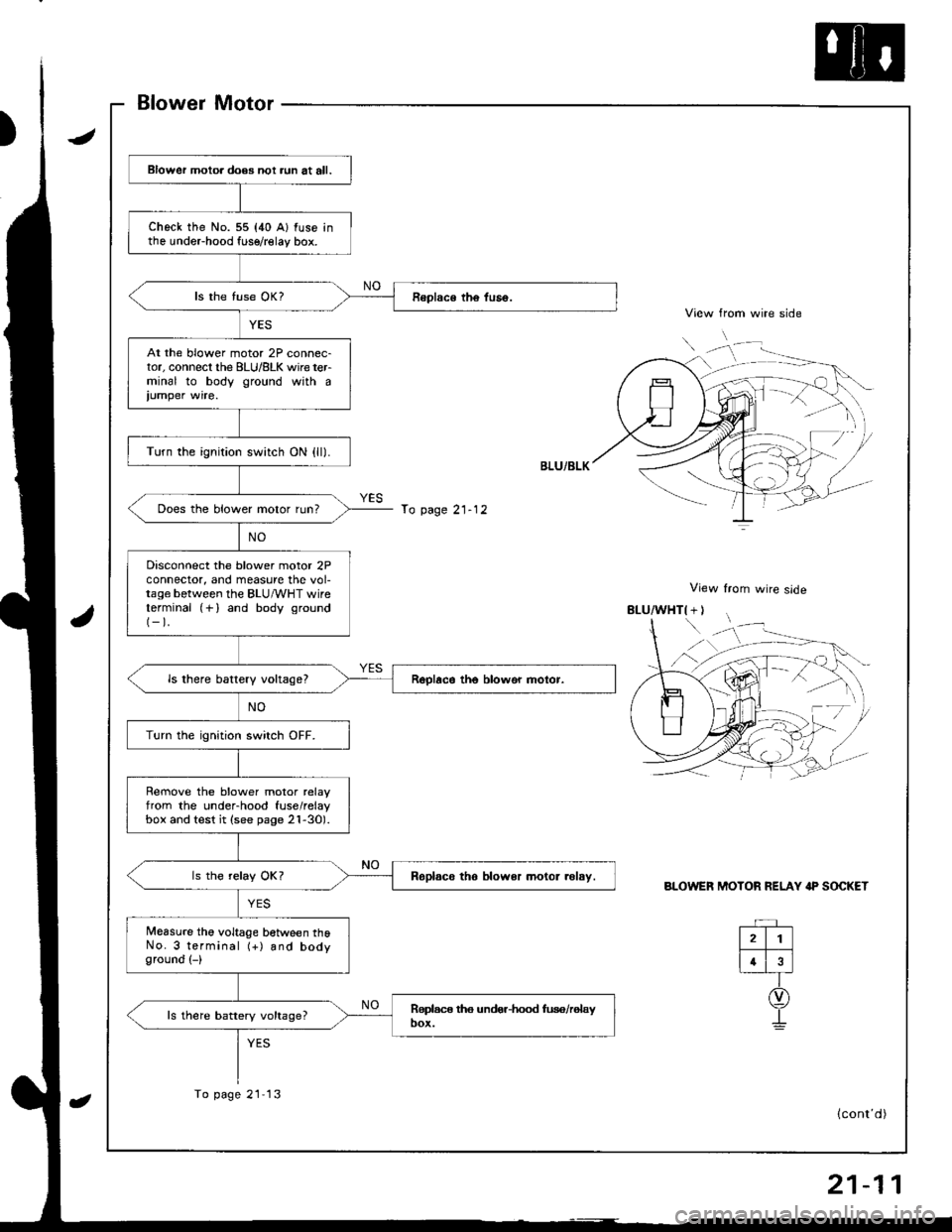
Blower Motor
View from wire side
View from wire slde
BLOWER MOTOR RELAY IP SOCKET
Blower motoa does not aun at all.
check the No. 55 {40 A} fuse inthe undeFhood fuse/relay box.
At the blower motor 2P connec-tor, connecl the BLU/8LK wire terminal to body ground with a
iumper wire.
Turn the ignition switch ON {ll).
Does the blower motor run?
Disconnect the blower motor 2Pconnector, and measure the vol-tage between the BLU/vVHT wireterminal (+) and body ground(-).
ls there battery vokagel
Turn the ignition switch OFF.
Rernove the blower motor relayfrom the under-hood fuse/relaybox and test it (see page 2l-30).
Roplsco tho blower motor .olsy.
Measure the voltage between thoNo. 3 terminal (+) and bodyground (-)
ls there battery voltage?
To page 21- 12
To page 21 13
rD
(cont'd)
Page 1000 of 1681
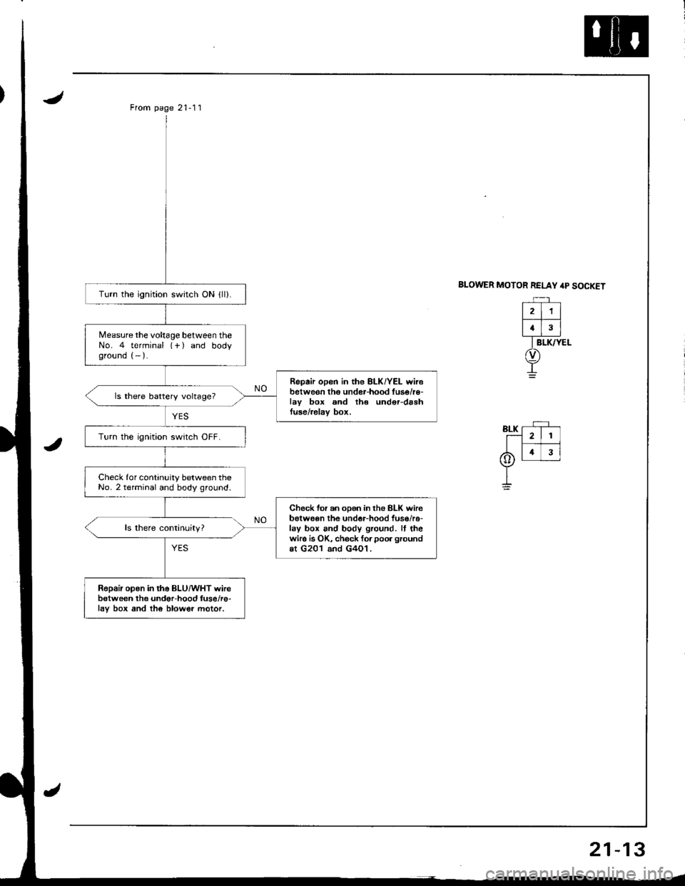
From page 21-11
BLOWER MOTOR RELAY /rp SOCKETTurn the ignition switch ON {ll).
Measure the voltage between theNo. 4 terminal (-f ) and bodyground (- ).
Repair open in the BLK/YEL wirebetweon tho under-hood tuse/r€-lav box and th€ und€r-drshtuse/relav box.
ls there battery voltage?
Turn the ignition swrtch OFF.
Check for continuity between theNo. 2 terminal and body ground.
Check for an oDen in the BLK wir€belween the undor-hood fuso/re-lay box and body ground. It thewire is OK, check forpoor groundat G201 and G4O1.
Ropair open in the BLU/WHT wirebetween the undor-hood fuse/re-lav box and the blow€r motor.
21
4
Page 1001 of 1681
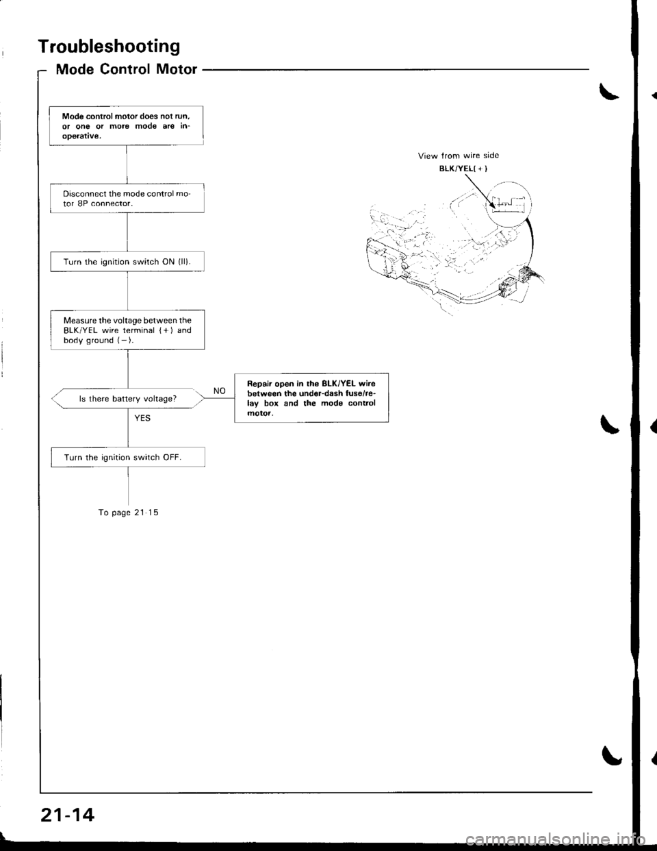
Troubleshooting
Mode Control Motor
Mode controlmotor does nol run.or ong or more mode are in-operatve.
Disconnect the mode control mo-tor 8P connector.
Turn the ignrtion switch ON (ll).
Measurethe voltage between theBLK/YEL wire terminal {+ ) andbody ground (- ).
Repair open in ths BLK/YEL wirebetween the und€r-dash fusehe-lay box and the mods cont.olmotoa,
Turn the ignition swirch OFF.
ls there battery voltage?
To page 21 15
21-14
Page 1025 of 1681
J
Troubleshooting
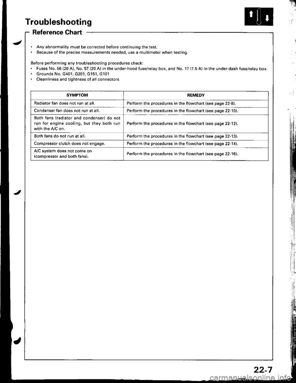
Reference Chart
. Any abnormality must be corrected before continuing the test.. Because of the precise measurements needed, use a multimeter when testing.
Before performing any troubleshooting procedures check:. Fuses No, 56 (20 A), No. 57 (20 A) in the under-hood fuse/relay box, and No. 17 {7.5 A) in rhe under-dash fuse/relay box.. Grounds No. G401, G201, G151, G101. Cleanliness and tightness of all connectors
I'IT
I
I
SYMPTOMREMEDY
Radiator fan does not run at all.Perform the procedures in the flowchart {see page 22-8).
Condenser fan does not run at all,Perform the procedures in the flowchart (see page 22-1O1.
Both fans {radiator and condenser) do not
run for engine cooling, but they both run
with the IVC on.
Perform the procedures in the tlowchart (see page 22-12).
Both fans do not run at all.Perform the procedures in the flowchart (see page 22-13).
Compressor clutch does not engage.Perform the procedures in the flowchart (see page 22-14).
l'lc system does not come on
{compressor and both fans).Perform the procedures in the flowchart (see page 22-15).
22-7
Page 1026 of 1681
Troubleshooting
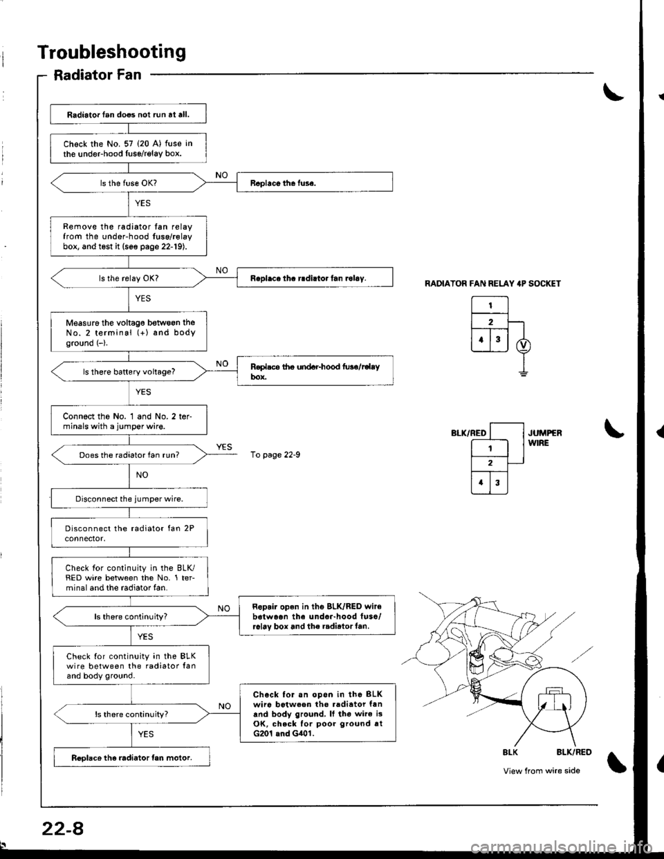
Radiator Fan
RADIATOR FAN RELAY 4P SOCKET
El2F-lt--T-- |
ujj I
I
",-*rrro [--l .u^rrrr
E lw'RE
l2-
trI
\
\
8LK BLK/RED
View from wire side\
Radiator lan does not run at all.
Chock the No. 57 (20 A) fuse in
the undeFhood fuse/relay box.
Remove the radiator tan relayfrom the under-hood fuse/rolaybox, and test it (see page 22-19).
Measuro the voltag€ betwogn theNo.2 terminal (+) and bodyground (-).
ls there battery voltage?
Connect the No. 1 and No. 2 ter-minals with a jumper wire.
Does the radiator fan run?
Check for continuity in the BLK/RED wire between the No. 1 ter-minal and the radiator fan.
Repair open in tho BLK/RED wir6b6twaon the undor-hood fuso/r6l6v box and the radirtorf6n.ls there continuity?
Check Ior continuity in the BLKwire between the radiator lanand body ground.
Chock for.n opon in tho BLKwiro botween tho .adiator fanand body ground, It tho wire i3OK, check for poor ground rtG201 and G401.
ls there continuity?
Roolace the radiator tan motor.
10 page 22-9
22-8