fuse box HONDA INTEGRA 1998 4.G Manual PDF
[x] Cancel search | Manufacturer: HONDA, Model Year: 1998, Model line: INTEGRA, Model: HONDA INTEGRA 1998 4.GPages: 1681, PDF Size: 54.22 MB
Page 1117 of 1681
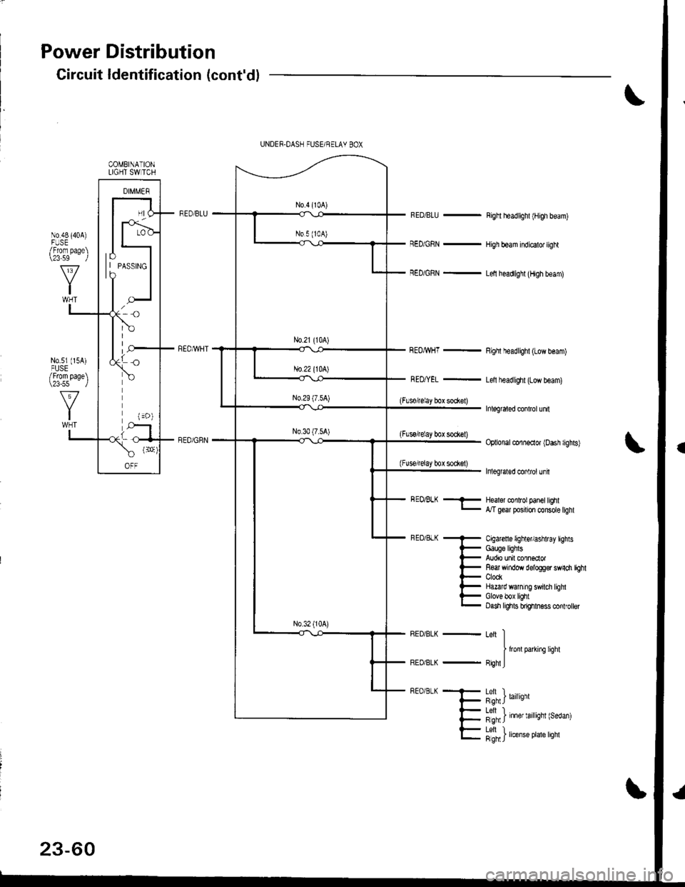
Power Distribution
Circuit ldentification (cont'd)
RED/BLU -
RED/GRN -
REOMHT -
Righl headlighl (High beam)
High beam indicalo. light
Lelt headlighl (High beam)
Righl headlighl (Low beam)
Letl headlighr (Low beam)
Inlegraled conlrol unn
Optional conneclor (Dash lighls)
Inleglaled conlrol unh
(Flsorelay box so*el)
(Flssrelay bot sock€l)
(Fuse/relay box sodet)
COMBINATIONLIGHT SW TCH
lo| | PAsslNGto
BEo/BLK -- Healor conlrol panel hghl- Mgear posrton consote tighl
Cigarcfl 6 lighter/ashtray lightsGauge lighlsAudio unit connsclorR€ar window delogg€r swnch tbhtClockHazard wanlng swilci lighlGlove box lightOash lights bnghhess conlroller
Leit II
I lronlparkifC lighl
FighlJ
h",J'n') '"",.*
l"fn' ) 'nn., '.', 'nnt {r"o"n)
23-60
Letl L.Rgh I rrense Prale lrgnl
Page 1119 of 1681
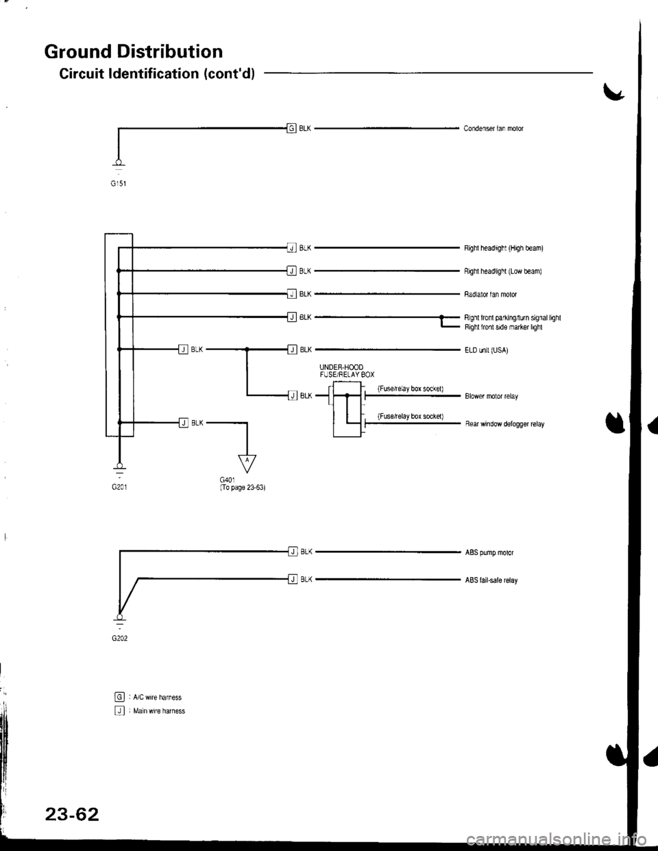
Ground Distribution
Circuit ldentification (cont'd)
Condenser laf molor
8LK
BLK
BLK
Righl headlighl (High beam)
Righl headlighl (Low beam)
Badiator lan molor
'LK ------
li;li fil Hi l'iff il"1"'"'
ELD unit (USA)
UNDER.HOODFUSE/RELAY BOX
: {Fuse/relayboxsockel)Blower molor relay
, (Fuseirelayborsochel)iear wnoow oerogger reray
G201
"--l-
VG401(To page 23-63)
AgS pump motor
ABS lailsale relay
@ , ac,nir" n",n"..
U Malnwire harness
23-62
Page 1120 of 1681
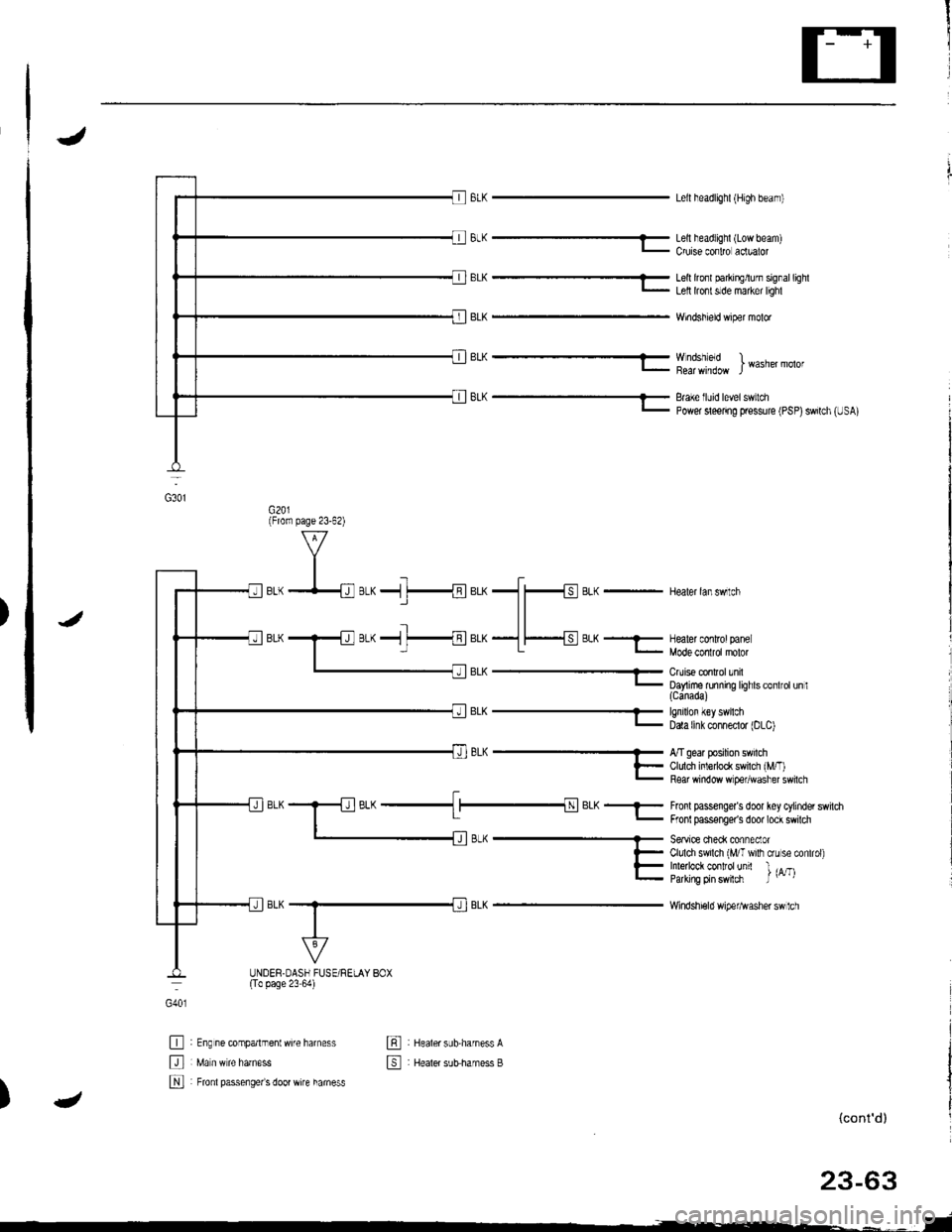
J
BrK-
BrK---
Lell headlighl {High beam)
Lell headlighl (Low beam)Cruise conlro aclualor
Lell lrcfl parkirElurn signallighlLell lront slde maker lighl
Windshield wiper molor
Wndshleld )I Wasner molor
Brake lluid level switchPower sleenng pressure (PSP)swilch (USA)
BLK - Healer lanswlch
J
EL^- Enrlron {€y swrcn- Data [nk conneclor |DLC)
BL(
Fronl passenge/s door key cylinder switdrFronl passonger's door lock swilch
Seavice cieck conneclorClulch swilch (MIT wilh crLr se conlrol)Inle ock contfolunit l ,^-,Parking prn swlch J u' t
Windshi€ld wipefl^Iasher sw 1ch
G40l
tr
tr
N
: Eng ne companmentwife harness
: Fronl passenge/s door wire hamess
: Healer sub.harness A
: Healer sutsharness B
tr
4)(cont'd)
G3o1
(From page 23-62)
;L^ ------ A/T gear posrron sw cn
l- Cldch inledock sw cl rM/.'- Fear window w pe,,wdsl'er sw cl
_l__{BLK_-
UNDER.OASH FUSE/RELAY BOX(To page 23 64)
Page 1121 of 1681
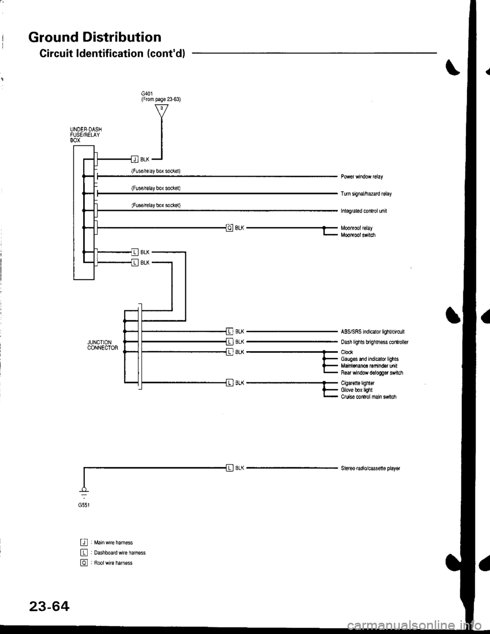
Ground Distribution
JUNCIIONCONNECTOR
U : Main wrre larness
E : oashboardwire haness
E , B*tr,it" h",n"..
Circuit ldentification (cont'dl
G40l(From page 23-63)
UNDEN.DASIFUSEi RELAYBOX
Turn sbnal/he2ad relay
hlegraled conlrol unil
BLh-Moonlmlleray- MooNool switch
BLK
BLK
8LK
ABS/SRS indicalor lighvci.dril
oash lighls brighhess clitroller
ClockGauges and indicalor lighlsMaiol€nan6 Gmind€a milR6ar window d6logger switch
A-^..'.''..'..- Cqal€nergrnet
l- Glove box lighlr- Ouise conlrol nan sw|ldr
Steleo mdio/cassello playel
G551
23-64
Page 1124 of 1681
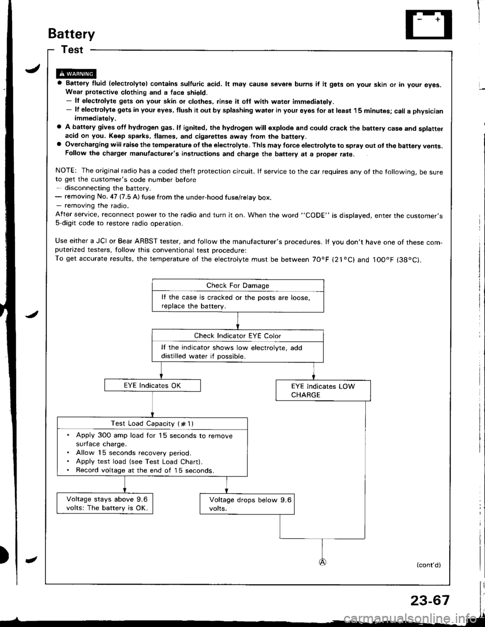
Battery
a Battery fluid (electrolytel contains sulfuric acid. lt may causo severe burns if it gsts on yout skin or in your eyes.Wear piotective clothing and a face shield.- ll electrolyte gets on your skin or clothes, rinse it ofl with water immediately.- lf electlolyte gets in your eyes, tlush it out by splashing water in your eyes for at least 15 minutes; call a physicianimmediately.
a A battery gives off hydlogen gas. lf ignited, the hydrogen will explode and could crack the battery case and splatte.acid on you. K6ep sparks, flames, and cigarettes away from the battery.a Overchalging will raisc the temperatulg of the electrolyte. This may force electrolyte to spray out ol the battery vents.Follow the chatge. manutacturer's instructions and charge the baftely at a ptope. rate.
NOTE: The original radio has a coded theft protection circuit. lf service to the car requires any of the tollowing, be sureto get the customer's code number before- disconnecting the battery.- removing No. 47 (7.5 A) fuse from the under-hood fuse/relay box.- removing the radio.
After service, reconnect power to the radio and turn it on. When the word "CODE" is displayed, enter tne customer's5-digit code to restore radio operation,
Use either a JCI or Bear ARBST tester, and follow the manufacturer's procedures. lf you don't have one of these com-puterazed testers, follow this conventional test Drocedure:To get accurate results, the temperature of the electrolyte must be between 70'F {21oC} and IOOoF (38oC).
lf the case is cracked or the posts are loose,
reDlace the batterv.
lf the indicator shows low electrolyte, add
distilled water if possible.
Test Load Capacity (# 1l
. Apply 3O0 amp load for 15 seconds to remove
surface charge.. Allow 15 seconds recovery period.. Apply test load {see Test Load Chart).. Record voltage at the end of l5 seconds.
Voltage stays above 9.6
volts: The battery is OK.
(cont'd)
Page 1128 of 1681
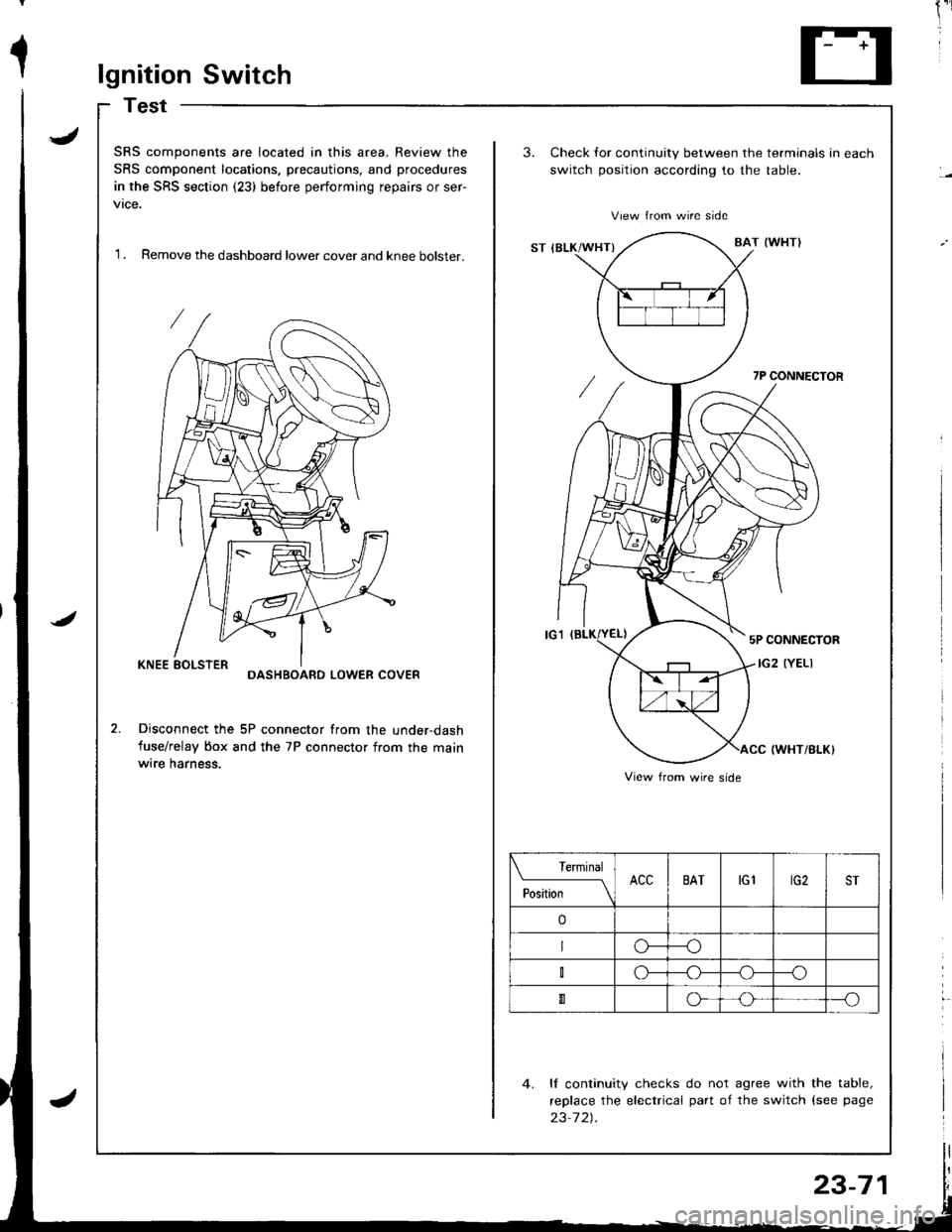
1lgnition Switch
Test
J
J
SRS components are located in this area. Review the
SRS component locations. precautions, and procedures
in the SRS section (23) before performing repairs or ser-
vtce.
'I . Remove the dashboard lower cover and knee bolster.
3.Check for continuity between the terminals in each
switch position according to the table.
View from wire side
ST IBLK/WHT}BAT (WI{TI
7P CONNECTOR
5P CONNECTOR
IG2 (YELIDASHBOARD LOWER COVER
Disconnect the 5P connector from the under-dash
fuse/relay box and the 7P connector from the mainwrre harness.IWHT/BI-K}
4. ll continuity checks do not agree with the table,
replace the electrical part of the switch {see page
23-7 2).
View from wire side
Terminal
PositionACCBATtGlrG2ST
o
o---o
o--_o
0o---o
23-71
Page 1129 of 1681
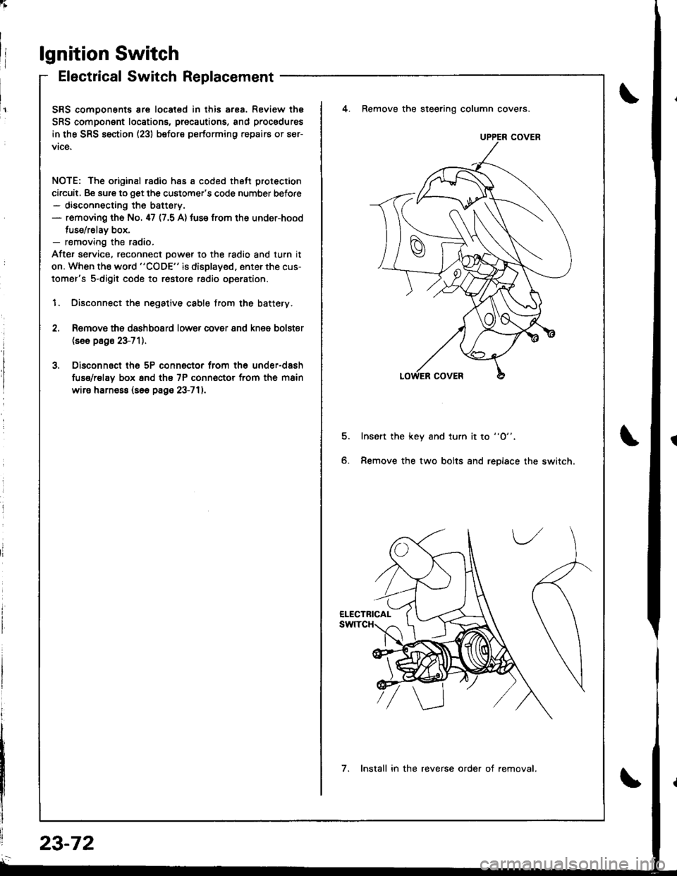
lgnition Switch
Electrical Switch Replacement
SRS comoonents are located in this ar8a. Review thE
SRS component locations, precautions, and procedures
in the SRS section (23) before performing repairs or ser-
vice.
NOTE: The original radio has a coded thett protection
circuit, Be sure to get the customer's code number before- disconnecting the battery.- removing th6 No. 47 (7.5 A) tuse from the under-hood
tuse/relav box,- removing the radio.
After service, reconnect oower to the radio and turn it
on. When the word "CODE" is displayed, enter the cus-
tomer's s-digit code to restore radio operation.
1. Disconnect the negative cable from the battery.
4. Remove the steering column covers.
Romovs ths dashboard lower cover 8nd knes bolster(se6 p8g6 23-71).
Disconnsct th6 5P connector from th6 under-dash
fuse/rel8y box 6nd th€ 7P conn€ctor from the main
wire harne$ (s6e page 23-711.
5.Insert the key and turn it to "O".
Remove the two bolts and replace the switch6.
UPPER COVER
7. Install in the reverse order of removal.
23-72
Page 1130 of 1681
;
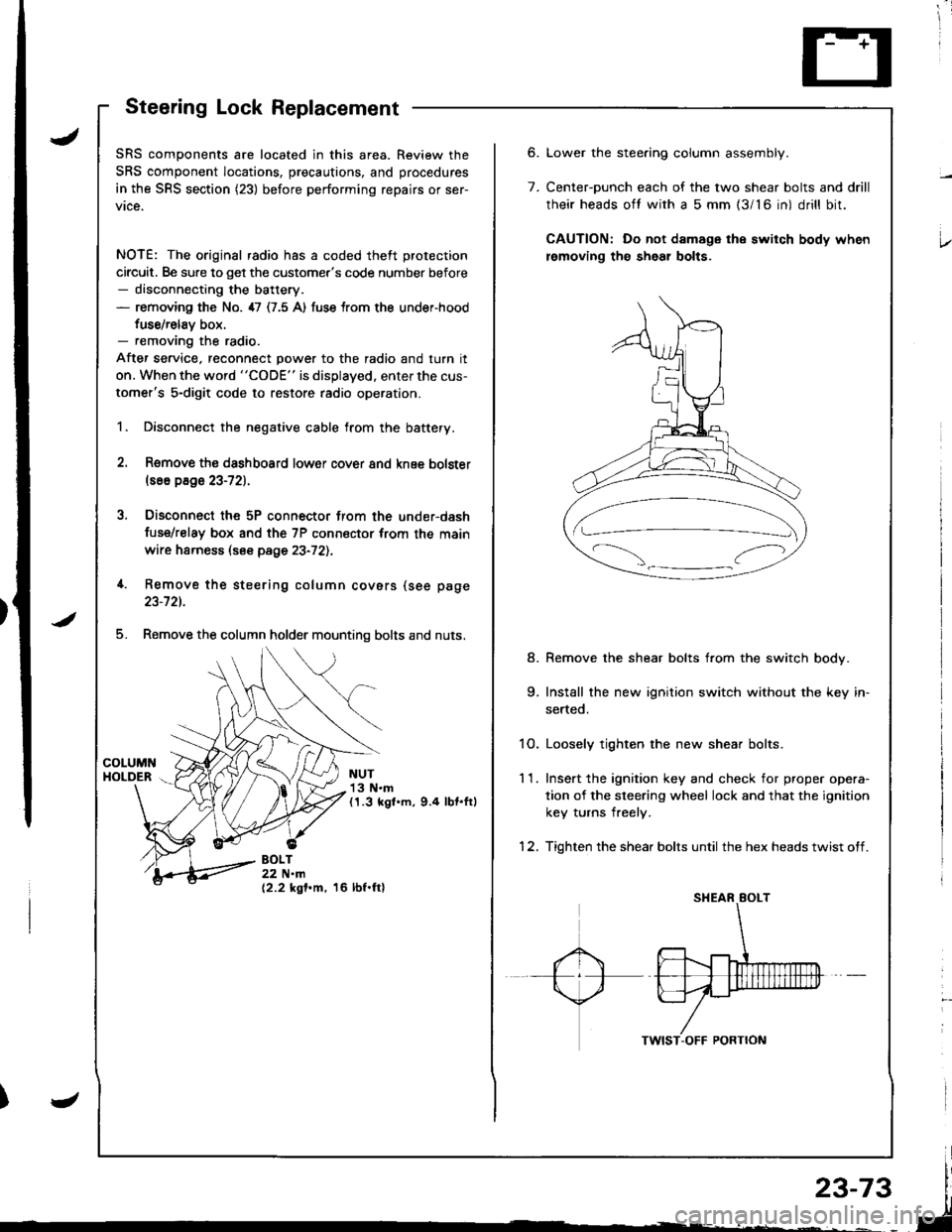
Steering Lock Replacement
SRS components are located in this area. Review the
SRS component locations, precautions, and procedures
in the SRS section (23) before performing repairs or ser-
vice.
NOTE: The original radio has a coded theft protection
circuit. Be sure to get the customer's code number before- disconnecting the battery.- removing the No. 47 (7.5 A) fuse trom the under-hood
fuse/relav box.- removing the radio.
After service, reconnect power to the radio and turn it
on. When the word "CODE" is displayed. enter the cus-
tomer's 5-digit code to restore radio operation.
1. Disconnect the negative cable from the battery.
2. Remove ths dsshboard lower cover and knee bolster(s6o p8ge 23-72).
3, Disconnect the 5P connector from the under-dash
fuse/relay box and the 7P connsctor from th€ main
wire harness (see page 23-72l.,
4. Remove the steering column covars (see page
23-721.
5. Remove the column holder mounting bolts and nuts.
NUT13 N.m(1.3 kgl.m, 9.4 lbt.ftl
BOLT22 N.m(2.2 kgf.m, 16 lbf.ftl
6.
7.
Lower the stee.ing column assembly.
Center-ounch each of the two shear bolts and drill
their heads oft with a 5 mm {3/16 in) drill bit.
CAUTION: Do not damage the switch body when
lemoving th€ sheal bolts.
Remove the shear bolts from the switch body.
Install the new ignition switch without the key in-
serted.
1O. Loosely tighten the new shear bolts.
11. Ins€rt the ignition key and check for proper opera-
tion of the sleering wheel lock and that the ignition
key turns freely.
12. Tighten the shear bolts until the hex heads twist off.
8.
Page 1132 of 1681
![HONDA INTEGRA 1998 4.G Manual PDF Circuit Diagram (M/Tl
tJ
STARTEBCUT RELAY
)/
ll-G2o1G401
rAa rtFz5- r3
) -rr
CLUTCHINTERLOCKSW]TCH
IGNITIONX SWITCH
!_*",.^-*-G-l
"T"
BTKWHT BLKWHT
llr - tr |
BLKFED 8LU/BLK
- BLK,BE I__-lrror.oo*
I HONDA INTEGRA 1998 4.G Manual PDF Circuit Diagram (M/Tl
tJ
STARTEBCUT RELAY
)/
ll-G2o1G401
rAa rtFz5- r3
) -rr
CLUTCHINTERLOCKSW]TCH
IGNITIONX SWITCH
!_*",.^-*-G-l
"T"
BTKWHT BLKWHT
llr - tr |
BLKFED 8LU/BLK
- BLK,BE I__-lrror.oo*
I](/img/13/6069/w960_6069-1131.png)
Circuit Diagram (M/Tl
tJ
STARTEBCUT RELAY
)/
ll-G2o1G401
rAa rtFz5- r3
) -rr
CLUTCHINTERLOCKSW]TCH
IGNITIONX SWITCH
!_*",.^-*-G-l
"T"
BTKWHT BLKWHT
llr - tr |
BLKFED 8LU/BLK
- BLK,BE' I__-lrror.oo*
I I
+Yffii'"'Tf'o' | |
u"T-l
i,t^il'r** | |
=-T--. I
twt t
l$*Tl r
IA II
BLK
tY--lt I-|ffim-
|
rl
UNDEB HOOD FUSE/BELAY BOX
No 41 (100A) N0.42 (404)
Page 1134 of 1681
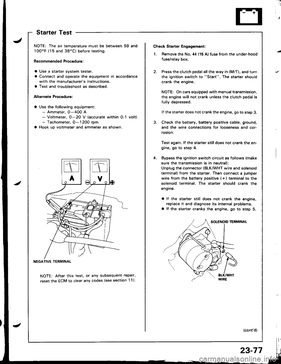
Ch6ck Starter Engag€mont;
1. Remove the No. 44 (15 A) fuse from the under-hood
fuse/relay box,
Press the clutch pedal all the way in (M/T), and turn
the ignition switch to "St8rt". The staner should
crank the engine,
NOTE: On cars equipped with manual transmission,
the engine will not crank unless the clutch pedal is
fully depressed.
lf the starter does not crank the engine, go to step 3.
Check the battery, battery positive cable, ground,
and the wire connections for looseness and cor-
rosion.
Test again. lf the stsner stilldoes not crank the en-
gine, go to step 4.
Bypass the ignition switch circuit as follows {make
sure the transmission is in neutral)
Unplug the connector (BLKMHT wire and solenoid
terminal) trom the staner. Then connect a jumper
wire from the batterv positive (+ ) terminal to the
solenoid terminal. The starter should crank the
engine.
a It the stsrter still does not crank the engine,
replace it and diagnose its internal problems,
a lf the starter cranks the engine. go to step 5.
(cont'd)
4.
NOTE: The air temperature must be between 59 and
100oF {15 and 38'C) betore testing.
Recommended Procedure:
a Use a starter system tester.
a Connect and operate the equipment in accordance
with the manufacturer's instructions.
a Test and troubleshoot as described.
Alternate Procodure:
a Use the following equipment;- Ammeter, O-400 A- Voltmeter. O-20 V (accurate within O,1 volt)- Tachometer, O- 1 2OO rpm
a Hook up voltmeter and ammeter as shown.
NEGATIVE TERMINAL
NOTE: Atter this test, or any subsequent repalr,
reset the ECM to clear any codes (see section 1 1).
StartelTest
23-77