change time HONDA INTEGRA 1998 4.G Workshop Manual
[x] Cancel search | Manufacturer: HONDA, Model Year: 1998, Model line: INTEGRA, Model: HONDA INTEGRA 1998 4.GPages: 1681, PDF Size: 54.22 MB
Page 245 of 1681
I
t
h,,l,!
il
Troubleshooting
ECM CONNECTOR {31P)
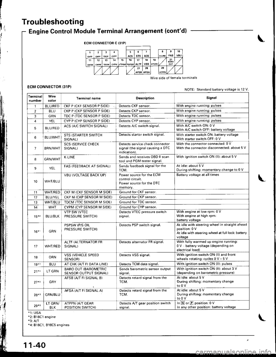
Engine Control Module Terminal Arrangement (cont'd)
ECM CONNECTOR C {31P)
235srsscs1112t31515t71A19
2A
Wire side of lemale terminals
NOTE: Standard battery voltage is 12 V.
TerminalnumbercolorTerminal namoD6scriptionSignal
1BLU/REDCKF P (CKF SENSOR P SIDE)Detects CKF sensor.With engine running: pulses
28LUCKP P (CKP SENSOR P SIDE)Detects CKP sensor.With engine running: pulses
3GRNTDC P {TDC SENSOR P SIDE)Detects TDC sensor,With engine running: pulses
YELCYP P (CYP SENSOR P SIDE)Detects CYP sensor,With engine running: pulses
5BLU/REDACS (AJC SWITCH SIGNAL)Detects A,/C switch signal.With A,/C switch ON: 0 VWith A,/C switch OFF: battery voltage
6BLUA/VHTSTS (STARTEB SWITCHSIGNAL)
Detects starter switch signal.With staner switch ON: battery voltageWith starter switch OFF: 0 V
7BRN,AiVHTSCS (SERVICE CHECKSIGNAL)Detects service check connectorsignal (the signalcausing a DTC;ndication).
With the co n nector con nected: 0 VWath the connector disconnected: about 5 V
8GRNAVHTK LINESends and receives OBD ll scantool and PGM tester signal.With ignition switch ON (ll): about 5 V
9YELFAS lFEEDBACK AT SIGNAL)Sends feedback signal for theTCM,At idle: about 5 VDuring shifting: momenlary change to 0 V
10WHT/BLU
VBU (VOLTAGE BACK UP)Power source for the ECMcontrolcircuit,Power source for the DTC
Battery voltage at all times
t1WHT/REDCKF M (CKF SENSOR I\4 SIDE)Ground for CKF sensor.
12BLUI/E LCKP M (CKP SENSOR M SIDE)Ground for CKP sensor.
WHT/BLUTDCM (TDC SENSOR M SIDE)Ground tor TDC sensor.
14CYPM (CYP SENSOR M SIDE)Ground for CYP sensor.
15*.BLU/BLKVTP SW (VTEC
PRESSUFE SWITCH)Detects VTEC pressure switchsr9nal.
With engine at low rpm:0 VWith engine at high rpmlbattery voltaqe
161,GRN
PSPSW (P/S OILPRESSURE SWITCH)Derecls PSP switch signal.At idle with steering wheel in straight aheadpositioni 0 VAt idle with steering wheelat full lock: batteryvoltage
17WHT/REDALTF (ALTERNATOR FRSIGNAL)Detects alternator FR signal.With fully warmed up engine running:0 V battery voltage (depending onelectrical load)
18ORNVSS (VEHICLE SPEEDSENSORiDetects VSS signal.With ignition switch ON (ll) and lrontwheels rotating: cycles 0 V- 5 V
19*3BLUAT CHK (A/T FI DATA LINE)Detects TCM data signal.With ignition switch ON (ll)i pulses
21*LT GRNBARO OUT (SAROMETRIC
SENSOR OUTPUT S!GNAL)Sends barometric sensor outputsrgnal,With ignition switch ON (ll): about 3 V(depending on barometric pressure)
27 x3GRYAFSB (A"/T FI SIGNAL B)Detects retard signal from theTCM,At idle: about 5 VDuring shifting: momentary changeto0V
28+1GRN/8LUA+SA (A/T FI SIGNAL A)Detects retard signal from theTCM.At idle: about 5 VDuring shifting: momentarV changeto0V
29+3LT GRN/BLKATPPN (A/T GEARPOSITION SWITCH)Detects A,/T gear position switchsrgnal-In E orE positionr 0VIn anv other position: battery voltage
*1: USA*2:818C1 engine*3: A/T*4: 818C1, 818C5 engines
Page 268 of 1681
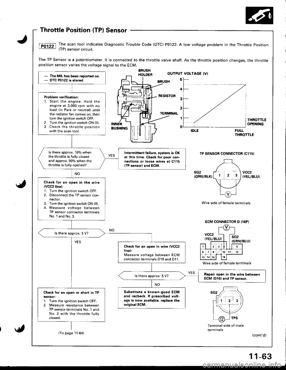
The scan tool indicates Diagnostic Trouble Code (DTC) P0122: A low voltage problem in the Throttle Position{TP) sensor circuil.
The TP Sensor is a potentiometer. lt is connected to the throttle valve shaft. As the throttle position changes, the throttleposition sensor varies the voltage signalto the ECM.
ARUSHHOI.DER
BRUSH 5
FULLTHROTTLE
TP SENSOR CONNECTOR IC115)
Wire side of temale terminals
ECM CONNECTOR D {16P)
(GRN/BLUI
Wire side ot female terminals
sG2 / -\
fr rrr r 'tr\
- 1 2 3)
|{- f- /
| _-,/tlI /6 I TPS-\j/
Terminalside of maletermrnats(To page 11-64)
The MIL has be€n reDort€d on.DTC P0122 is stor€d.
Problem veritication:1. Start the engine. Hold theengine at 3,000 rpm with noload (in Park or neutral) untilthe radiator fan comes on, thenturn the ignition switch OFF.2. Turn the ignition switch ON (ll).
3. Check the throttle positionwith the scan tool.
ls there approx. 10% whenthe throttle is fully closedand approx.90o/o when thethrottle is fully opened?
lntermittenl tailure, system is OKat this time. Check tor poor con-nections or loose wires at Cl15{TP s€nsor) end ECM.
Check lor an open in ihe wire(VCC2line):
1. Turn the ignition switch OFF.2. Disconnect the TP sensor con,nector,3. Turn the ignition switch ON (ll).4. Measure voltage betweenTP sensor connector terminalsNo. l and No. 3.
ls there approx. 5 V7
Check fo. an open in wire IVCC2line):lleasure voltage between ECMconnector terminals D10 and D11.
R.p.ir opon in tho wire betwoenECM {D101 and TP sen3or.ls there approx. 5 V?
Substitute a known-good ECMand recheck. lf pr6sc.ibed volt-age ia now available, replaco theoriginalECM.
Check for an open or 3hort in TP3ensor:1. Turn the ignition switch OFF.2. Measure resistance betweenTP sensor terminals No. '1 andNo.2 with the throttle fullyctoseo,
OUTPUT VOLTAGE {V)
4
RESISTOR3
2
TERMINAL
I
o
THROTTLEOPEI{INGBUS}IINGIDLE
sG2{GRN/BLK)vcc2IYEL/BLU}
vcc2{YEL/BI
l\e
4E
i2iRN,
. llLI5
6/101t 12
t515
(cont'd)
Page 285 of 1681
PGM.FI
Misfire
System
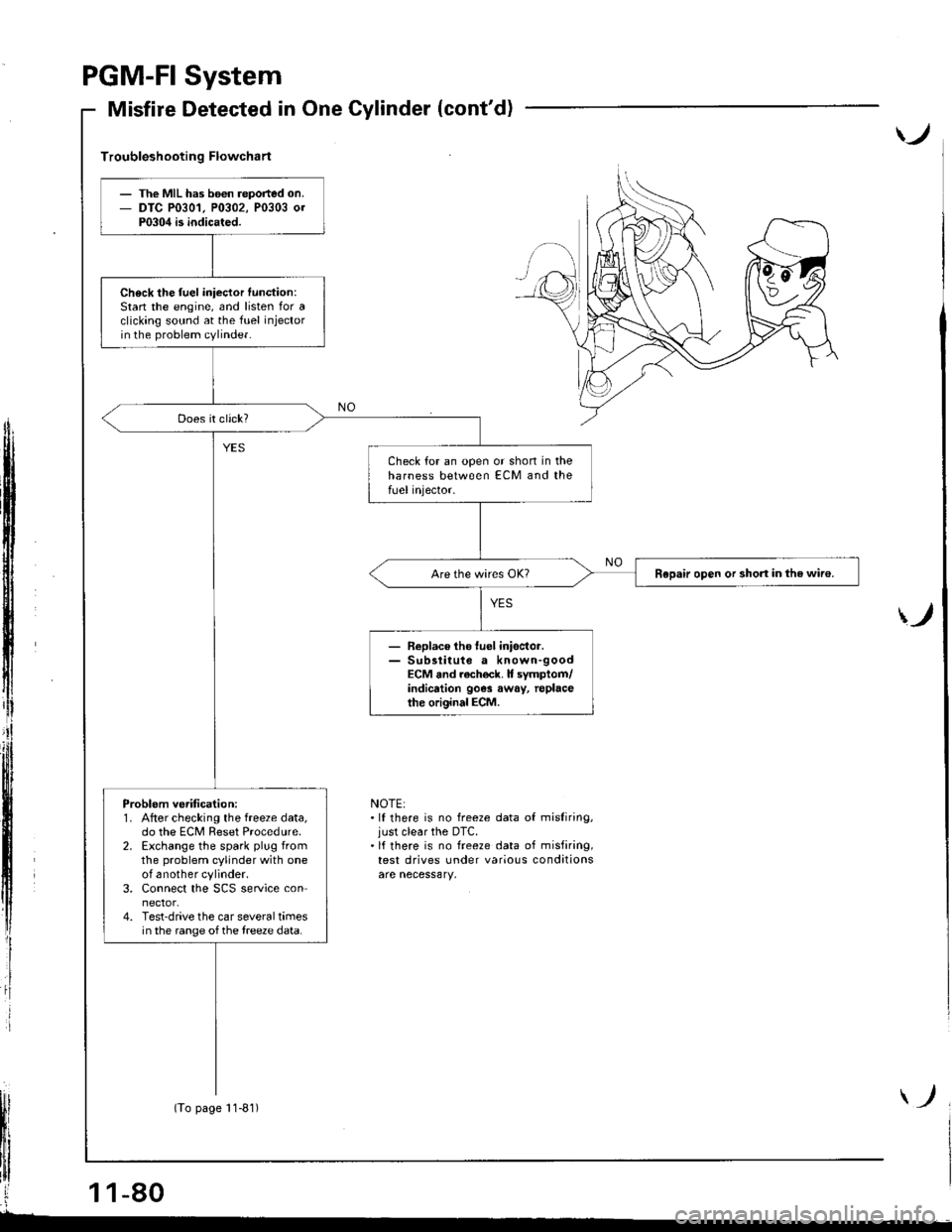
Detected in One Cylinder (cont'd)
)
Troubleshooting Flowchart
ff
i
)
NOTE:.lf there is no freeze data of misliring,just clear the DTC.'lf there is no freeze data of misfiring,test drives under various conditions
The MIL has b6€n reported on.DTC P0301, P0302, P0303 0rP0304 is indicated.
Check the fuel iniector function:Stan the engine, and listen for aclicking sound at the fuel injectorin the problem cylinder.
Check for an open or shon in theharness between ECM and thefUel injector.
Repair open or short in the wiro.
- Replace tho luel inisctor.- Sub3titute a known-goodECM and rach€ck. It symptom/indicrtion 90e3 away, replacethe original ECM.
Problem ve.ification:1. After checking the freeze data,do the ECM Reset Procedure.2. Exchange the spark plug fromthe problem cylinder with oneof another cylinder.3. Connect the SCS service connector.4. Test-drive the car several timesin the range of the treeze data.
(To page 11-81)
Page 286 of 1681
(From page l1-80)
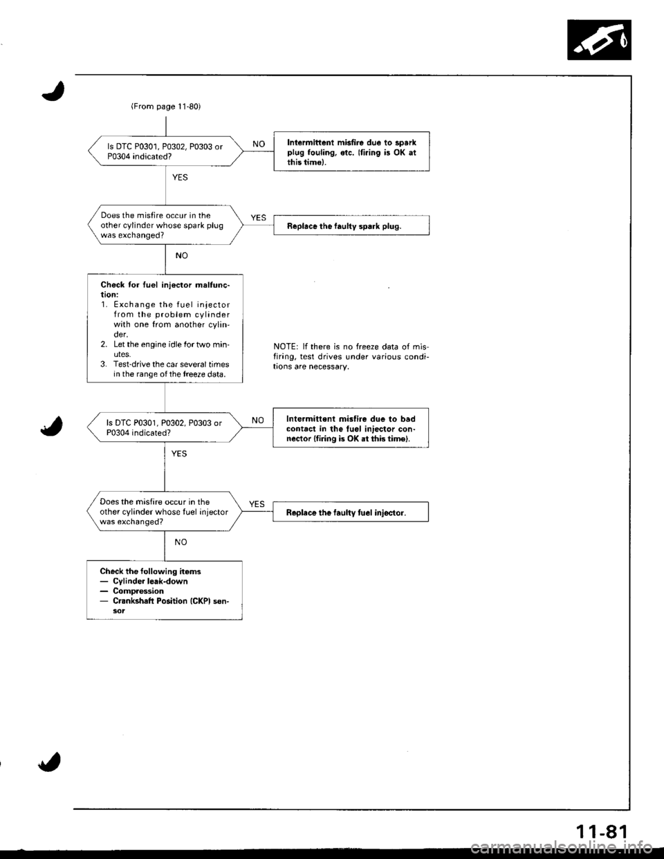
Iniermittenl misfire due lo sparkplug fouling, otc. Iti.ing is OK atthis timo).
Does the misfire occur in theother cylinder whose spark plugwas exchanged?Replace the faultv spark plug.
Check for tuel ini€ctor maltunc-taon:1. Exchange the fuel injectorfrom the problem cylinderwith one from another cylin'der.2. Let the engine idle lortwo min-uteS.3. Test-drive the car sevoraltimesin the range ofthe treeze data.
Int€rmitt€nt mislire due to badcontact in tho tuel iniector con-nector lfiring is OK at thb time).
Does the misfire occur in theother cylinder whose tuel injectorwas exchanged?Replace the laultv tuel iniector.
Check the following items- Cylinde. lerk-down- Compaession- Crankshafl Position (GKPI son-
NOTE: lf there is no freeze data of misfirang, test drives under various condi-trons are necessary.
1 1-81
Page 305 of 1681
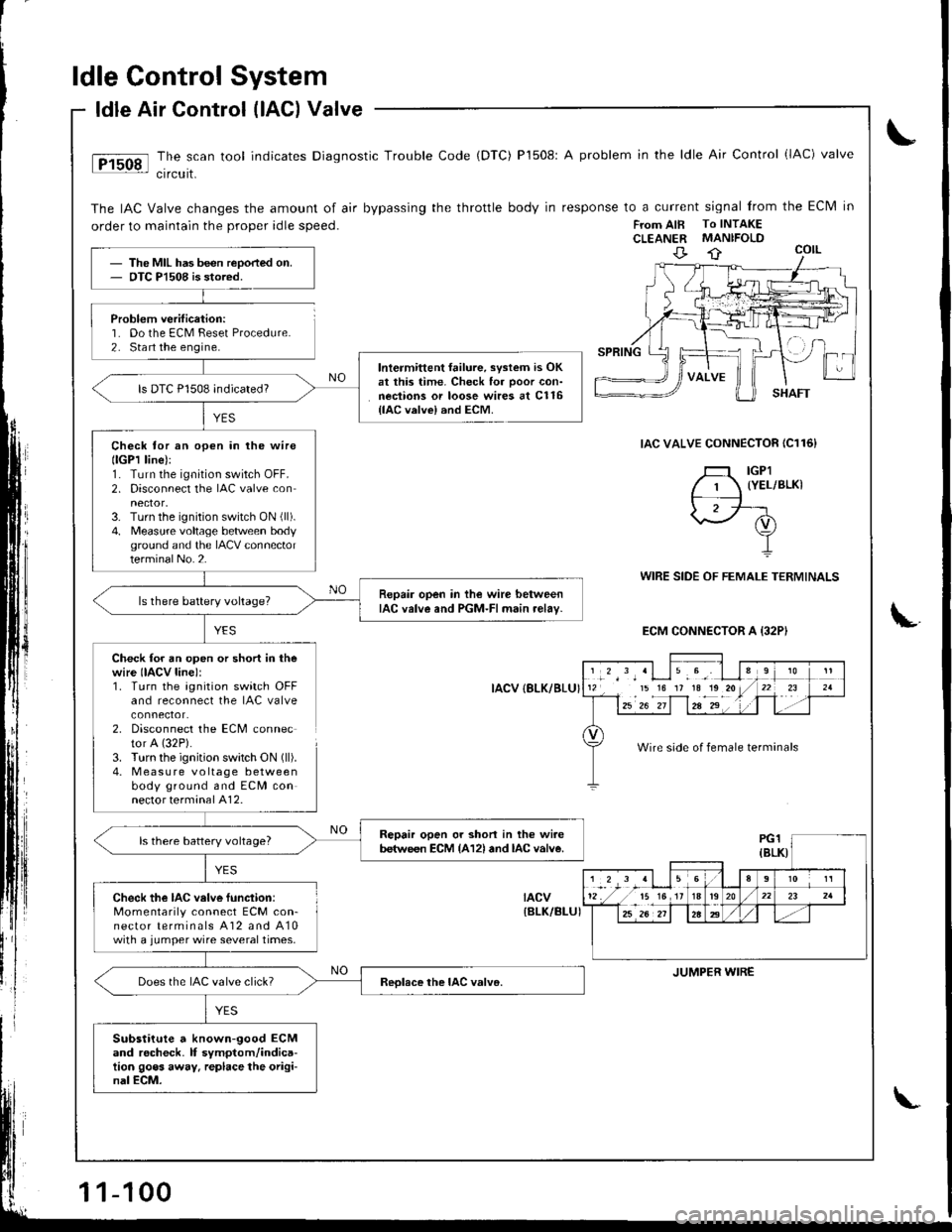
ldle Control System
Problem verification:'1. Do the ECM Feset Procedure.2. Sta rt the engine.
ldle Air Control (lAG) Valve
The scan tool indicates Diagnostic Trouble Code (DTC) P1508: A problem in the ldle Air Control (lAC) valve
crrcurt.
The IAC Valve changes the amount of air bypassing the throttle body in response to a current signal from the Eclvl in
order to maintain the proper idle speed.FTom AIB To INTAKECLEANER MANIFOLD
IAC VALVE CONNECTOR IC116}
YES
WIRE SIDE OF FEMALE TERMINALS
ECM CONNECTOR A {32PI
Check for an open or short in thewire IIACV line):1. Turn the agnition switch OFFand reconnect the IAC valve
2. Disconnect the ECM connector A (32P).
3. Turn the ignition swatch ON (ll).
4. M easu re voltage betweenbody ground and ECM connector terminal A12.
IACV {8LK/BLU}
tacv{BLK/BI-UI
The MIL has been reoorted on.OTC Pl508 is stored.
lntermittent failure, svstem is OKat this time. Check for ooor con-nections or loose wires at C116{lAC valvel and ECM.
ls DTC P1508 indicated?
Check tor an open in lhe wirellGPl line):1. Turn the ignition switch OFF.2. Disconnect the IAC valve con
3. Turn the ignition switch ON (ll).
4. Measure voltage betlveen bodyground and the IACV connectorterminalNo.2.
Repair open in the wire betweenIAC valve and PGM-FI main relav-ls there battery voltage?
Repair open or shon in the wi.ebetween ECM {A12l and lAc valve.ls there battery voltage?
Check the IAC velve function:Momentarily connect ECM con-nector terminals A12 and A10with a jumper wire several times.
Does the IAC valve click?
Substitute a known-good ECMand rocheck. lf symptom/indica-tion goes away. replace the origi-nal ECM.
','*',,'Llu.9', I l112 15 16 17 1a1o20/
l--12u1 z"-if1za-2"' . '1 .
910
t-r '21
Wire side of female terminals
JUMPER WIRE
1-100
Page 767 of 1681
1.
8.
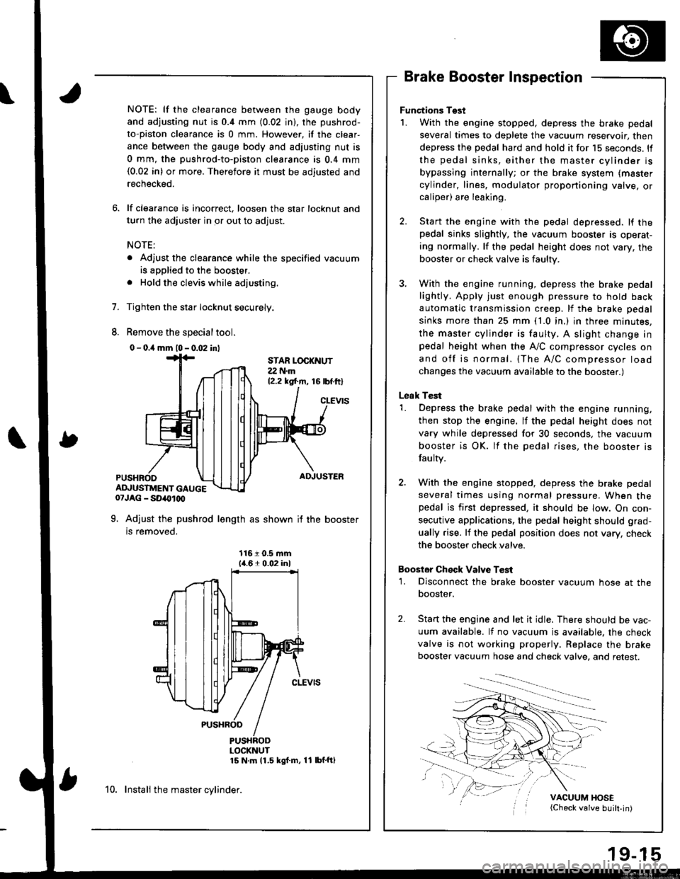
NOTE: lf the clearance between the gauge body
and adjusting nut is 0.4 mm (0.02 in), the pushrod-
to-piston clearance is 0 mm. However, if the clear-
ance between the gauge body and adjusting nut is
0 mm, the pushrod-to-piston clearance is 0.4 mm(0.02 in) or more. Therefore it must be adjusted and
rechecked.
lf clearance is incorrect, loosen the star locknut and
turn the adjuster in or out to adjust.
NOTE:
. Adjust the clearance while the specified vacuum
is applied to the booster.
. Hold the clevis while adjusting.
Tighten the star Iocknut securely.
Remove the special tool.
0 - o.il mm l0 - 0.02 inl
Brake Booster Inspection
Functions Tgst
1. With the engine stopped, depress the brake pedal
several times to deplete the vacuum reservoir, then
depress the pedal hard and hold it for 15 seconds. ll
the pedal sinks, either the master cylinder is
bypassing internally; or the brake system (master
cylinder, lines, modulator proportioning valve, orcaliper) are leaking.
Start the engine with the pedal depressed. lf thepedal sinks slightly, the vacuum booster is operat-
ing normally. lf the pedal height does not vary, the
booster or check valve is faulty.
With the engine running, depress the brake pedal
lightly. Apply just enough pressure to hold back
automatic transmission creep, lf the brake pedal
sinks more than 25 mm (1.0 in.) in three minutes,
the master cylinder is faulty. A slight change inpedal height when the A,,/C compressor cycles on
and off is normal. (The A/C compressor load
changes the vacuum available to the booster.)
Leak Test
1. Depress the brake pedal with the engine running,
then stop the engine. lf the pedal height does not
vary while depressed for 30 seconds, the vacuum
booster is OK. lf the pedal rises, the booster is
fau lty.
2. With the engine stopped, depress the brake pedal
several times using normal pressure. When thepedal is first depressed, it should be low. On con-
secutive applications, the pedal height should grad-
ually rise. lf the pedal position does not vary, check
the booster check valve.
Boostor Ch€ck Valve T6st
1. Disconnect the brake booster vacuum hose at the
booster,
Start the engine and let it idle. There should be vac-
uum available. It no vacuum is available. the check
valve is not working properly. Replace the brake
booster vacuum hose and check valve, and retest.
VACUUM HOSE(Check valve built-in)
STAR LOCKNUT22 t{.m12.2 ksl.m, 16lbf.ftl
cLEVtS
ADJUSTER
ADJUSTMENT GAUGE07JAG - SD40t00
9. Adjust the pushrod length as shown if the booster
is removed.
1161 0.5 mm14.61 0.02 inl
PUSHRODLOCKNUT15 N m 11.5 kgf m, 11 lbf'ftl
10. Instali the master cylinder.
Page 781 of 1681
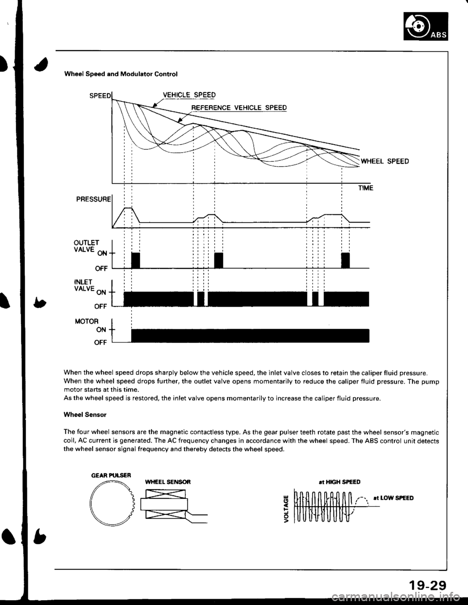
Wheel Speed and Modulator Control
OUTLETVALVE oN
OFF
INLETVALVE ON
OFF
MOTOR
ON
OFF
When the wheel speed drops sharply below the vehicle speed, the inlet valve closes to retain the caliper fluid pressure.
When the wheel speed drops further, the outlet valve opens momentarily to reduce the caliper fluid pressure. The pump
motor starts at this time.
As the wheel speed is restored, the inlet valve opens momentarily to increase the caliper fluid pressure.
Wheel Sensor
The four wheel sensors are the magnetic contactless type. As the gear pulser teeth rotate past the wheel sensor's magnetic
coil, AC current is generated. The AC frequency changes in accordance with the wheel speed. The ABS control unit detects
the wheel sensor signalfrequency and thereby detects the wheel speed.
rr LOW SPEED
5
GEAR PUTSER
19-29
Page 1554 of 1681
- How the Circuit Works
The security system control unit has a 3 position
switch: Manual. Auto. and Auto Lock. Here's what
happens when you arm the system, regardless ol
the switch position:
o The parking lights will flash once.
. The security indicator will flash once per second
after the system is armed.
With the switch in the Manual position, the security
system can only be armed by using the remote
control transmitter, After you remove the key from
the ignition and close all doors, the hood (if
equipped with the optional hood switch), the hatch
or trunk. Dress the lock button on the transmitter
and the system will arm (if the system is in the beep
sound mode, the horn will sound once). The doors
will automatically lock when the system is armed.
With the switch in the Auto position, the security
system will arm itself within about 20 seconds after
you turn the engine off, remove the key from the
ignition, and close the halch or trunk, the hood (if
equipped with the optional hood switch), or last
door. lf a door is opened during the 2o-second exit
delay time, the timer will reset itself . The remote
control transmitler can still be used to arm the
system with the switch in Auto position (see manual
for details).
With the switch in Auto Lock position, the security
system will arm itself and lock the doors about 20
seconds after you turn the engine of{, remove the
key from the ignition, and close the hatch or trunk,
the hood (if equipped with the optional hood
switch), or last door. lf a door is opened during the
2o-second exit delay time, the timer will reset. The
remote control transmitter can still be used to arm
the system in the Auto Lock position.
Triggering the Alarm
After the security system is armed, the sound ot
breaking glass or the opening of a door, hood,
hatch or trunk will trigger the alarm, and cause
the following:
r The horn will sound for30 seconds.
The optional siren will sound lor 60 seconds.
. The parking lights will flash.
. The security indicator LED will flash twice per
second.
. The starter will be disabled.
At the end of the alarm cycle, the system will
automatically rearm.
Disarming the Security System
There are two ways to disarm the security system:
. With the transmitter
o With the disarm/valet switch
When the system is disarmed, regardless of the
method used, the parking lights will flash two times if
the alarm has not been triggered and three times if
the alarm has been triggered. To disarm the system
with the transmitter, press the unlock button (if the
system is in the beep sound mode, the horn will
sound two times if the alarm has not been triggered,
however, will sound three times if the alarm has
been triggered). The driver's door will unlock
(pressing the unlock button twice will unlock all
doors).
To disarm the security system using the
disarm/valet switch, enter the car and turn the
ignition switch to ON (ll) then press the disarm/valet
switch button. lf you open the door when the control
unit switch is in Auto or Auto Lock, a 2o-second
entry delay will give you time to disarm the system.
However, when the system is armed by the
transmitter, the entry delay time is changed to zero
seconds, and the alarm is triggered as soon as you
oDen the door.
ldentifying Tripped Sensors
The system will indicate the sensor which triggered
the alarm through the security indicator LED. While
sitting inside the vehicle wlth the key out of the
ignition switch, all doors, the hood (if equipped with
the optional hood swilch), the hatch or trunk must be
closed. Press and hold the disarm/valet switch.
Press the lock button and then the unlock button of
the transmitter. Belease the disarm/valet switch. The
status LED will blink according to the following code:
Sensors
Door
Trunk/Hatch
System Switches
Glass Breakage
Hood (Optional)
Number ol Flashes
1 blink, pause, repeat
2 blinks, pause, repeat
3 blinks, pause, repeat
4 blinks, pause, repeat
5 blinks, pause, repeat
For further operating instructions and troubleshooting,
see the security system owner's manual.
133-5