service reset HONDA INTEGRA 1998 4.G Workshop Manual
[x] Cancel search | Manufacturer: HONDA, Model Year: 1998, Model line: INTEGRA, Model: HONDA INTEGRA 1998 4.GPages: 1681, PDF Size: 54.22 MB
Page 238 of 1681
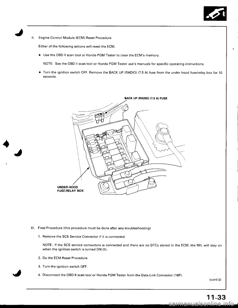
Engine Control Module (ECM) Reset Procedure
Either of the following actions will reset the ECM.
. Use the OBD ll scantool or Honda PGM Tester to clear the ECM'S memory.
NOTE: See the OBD ll scan tool or Honda PGM Tester use's manuals for specific operating instructions.
. Turn the ignition switch OFF. Remove the BACK UP (RADIO) (7.5 AI tuse from the under hood fuse/relay box for 10seconds.
BACK UP (RAOIO) {7.5 AI FUSE
UNDER'HOODFUSE/RELAY BOX
lll. Final Procedure (this procedure must be done after any trou bleshooting )
1. Remove the SCS Service Connector if it is connected.
NOTE: lf the SCS service connectors is connected and there are no DTCS stored in the ECM, the MIL will stav onwhen the ignition switch is turned ON (ll).
2. Do the ECM Reset Procedure.
3. Turn the ignition switch OFF.
4. Disconnect the OBD ll scan tool or Honda PGM Tester from the Data Link Connector (16P|.
{cont'd)
11-33
Page 275 of 1681
PGM-FI System
Primary,Heated Oxygen Sensor (HO2S) (Sensor 1) (cont'dl
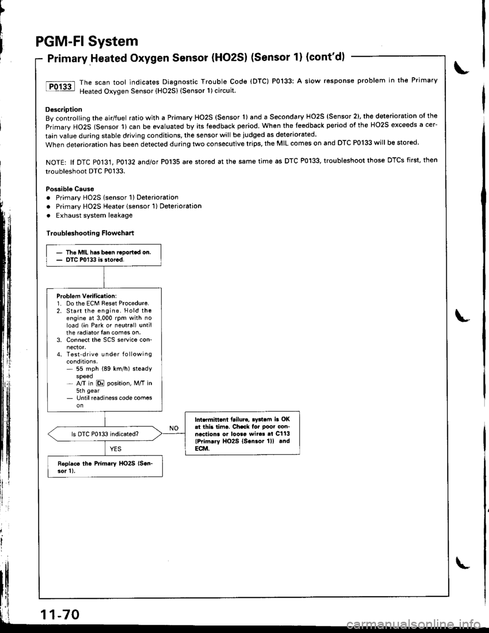
The scan tool indicates Diagnostic Trouble Code (DTC) P0133: A slow response problem in the Primary
Heated Oxygen Sensor (HO25) (Sensor 1) circuit.
Description
By controlling the airlfuel ratio with a Primary HO2S (Sensor 'l) and a Secondary HO2S (Sensor 2), the deterioration of the
primary HO2S {Sensor 1) can be evaluated by its teedback period. When the feedback period of the HO2S exceeds a cer-
lain value during stable driving conditions, the sensor will be judged as deteriorated.
When deterioration has been detected during two consecutive trips, the MIL comes on and DTC P0133 will be stored
NOTE: ll DTC P013't, P0132 and/or P0'135 are stored at the same time as DTC P0133, troubleshoot those DTCS first, then
troubleshoot DTC P0133.
Possible Cause
. Primary HO2S (sensor 1) Deterioration
o Primary HO2S Heater (sensor 1) Deterioration
. Exhaust system leakage
Troubl€shooting Flowchart
')
litll r
- Tho MIL has boon raDortcd on.- DTC P0133 is storcd.
Problem verificttion:1. Do the ECM Reset Procedure.2. Start the engine. Hold thoengine at 3,000 rpm with noload (in Park or neutral) untilthe radiator fan comes on.3. Connect the SCS service con-
4. Test'drive Lrnder f o llowingconditions.* 55 mph (89 km/h) steadyspeed- NT in E position, M/T in5th gear- Until readiness code com€son
lnt.flnittcnt ftilu... ay3tam ia OKat thb tiinr. Ch.ck fo. poor con-necliona o. looaa wita! al Cll3
lPrim.ry HO2S lscn.or lll lndECM.
ls DTC P0133 indicated?
Roplacs the Primary HO2S lscn-3or 1),
Page 285 of 1681
PGM.FI
Misfire
System
Detected in One Cylinder (cont'd)
)
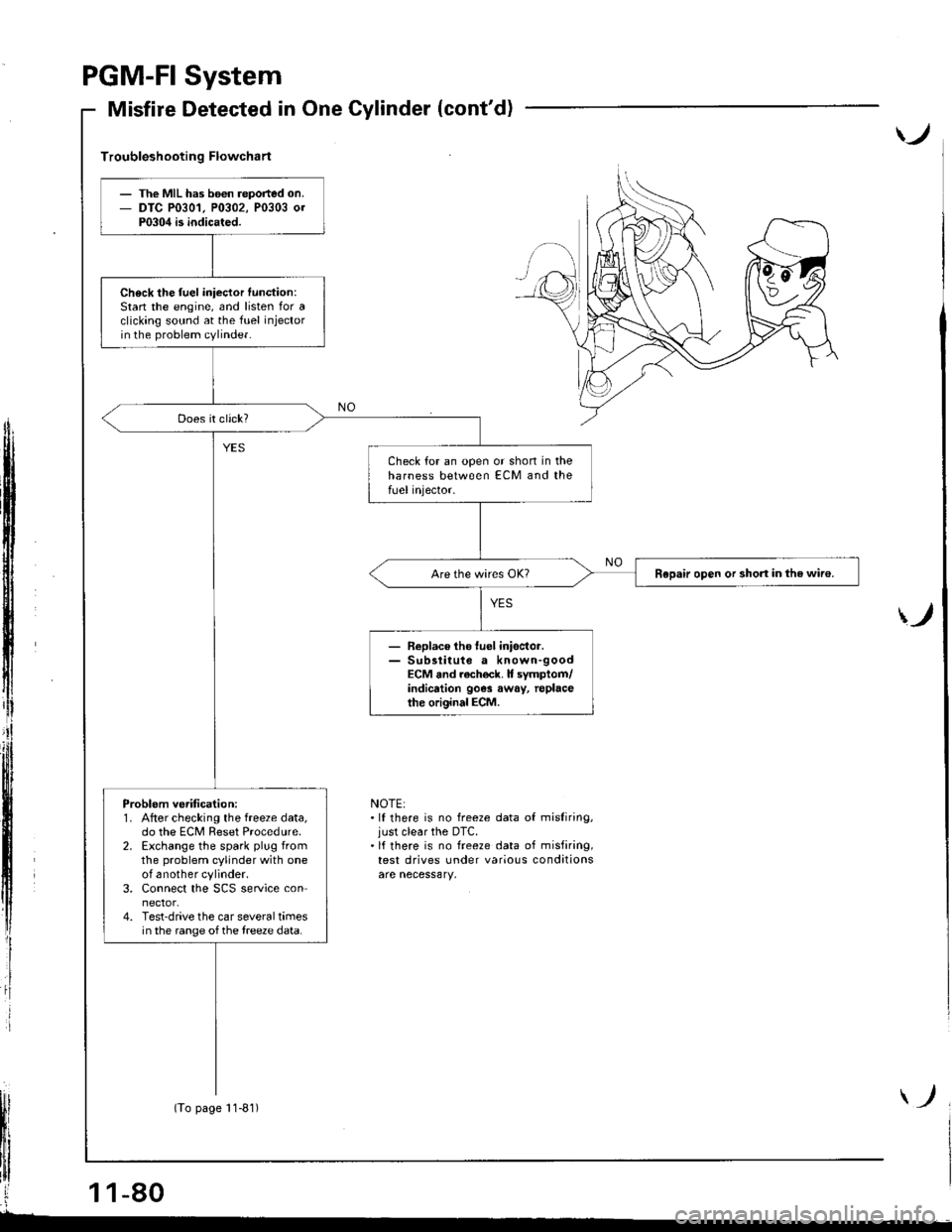
Troubleshooting Flowchart
ff
i
)
NOTE:.lf there is no freeze data of misliring,just clear the DTC.'lf there is no freeze data of misfiring,test drives under various conditions
The MIL has b6€n reported on.DTC P0301, P0302, P0303 0rP0304 is indicated.
Check the fuel iniector function:Stan the engine, and listen for aclicking sound at the fuel injectorin the problem cylinder.
Check for an open or shon in theharness between ECM and thefUel injector.
Repair open or short in the wiro.
- Replace tho luel inisctor.- Sub3titute a known-goodECM and rach€ck. It symptom/indicrtion 90e3 away, replacethe original ECM.
Problem ve.ification:1. After checking the freeze data,do the ECM Reset Procedure.2. Exchange the spark plug fromthe problem cylinder with oneof another cylinder.3. Connect the SCS service connector.4. Test-drive the car several timesin the range of the treeze data.
(To page 11-81)
Page 344 of 1681
Three Way Catalytic Converter (TWC)
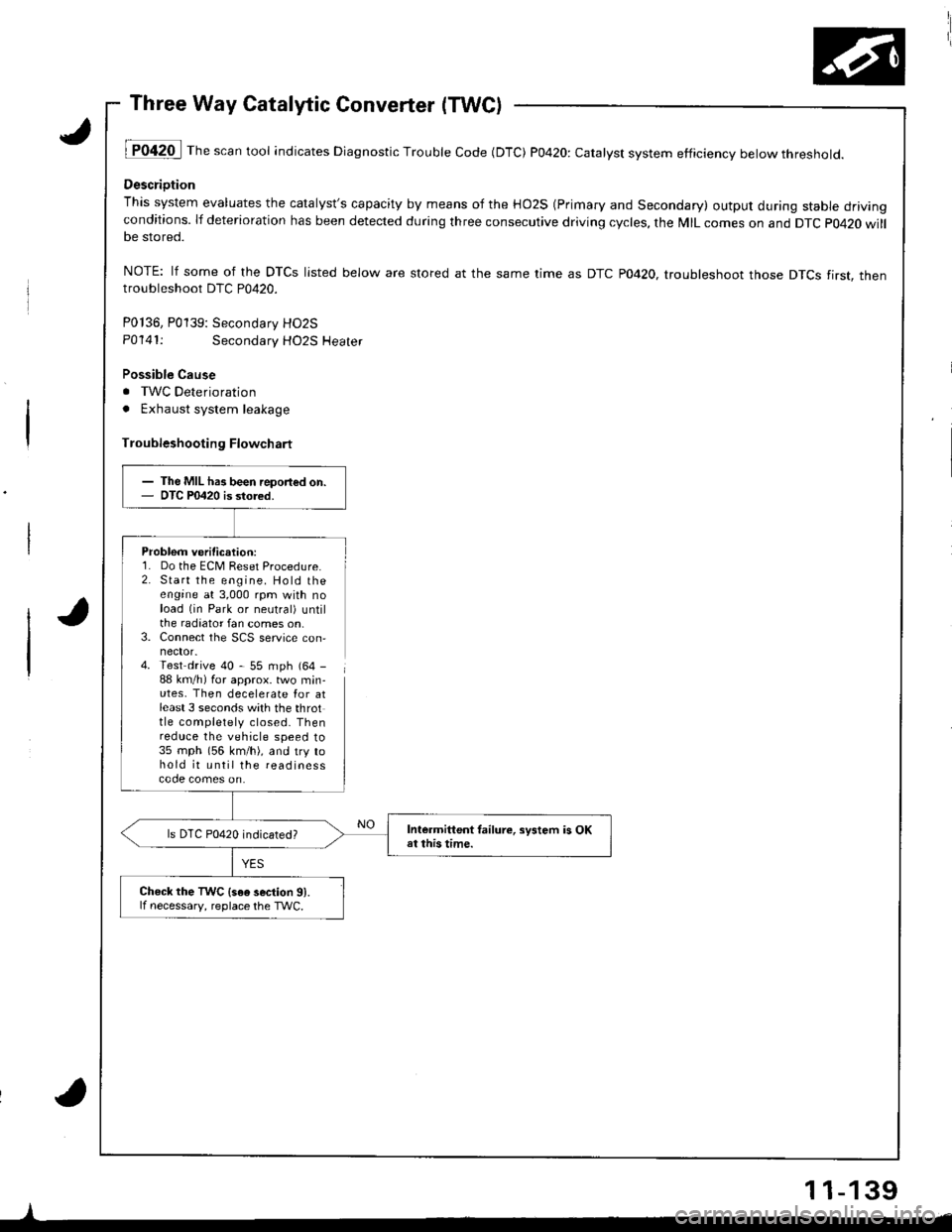
lT042O I Th" """n tool indicates Diagnostic Trouble Code (DTC) P0420: catatyst system efficiency below threshold.
Descriotion
This system evaluates the catalyst's capacity by means of the HO2S (Primary and Secondary) output during stable drivingconditions. lf deterioration has been detected during three consecutive driving cycles, the MIL comes on and DTC p0420 willbe stored.
NOTE: lf some of the DTCS listed below are stored at the same time as DTC PO42O. troubleshoot those DTCS tirst. thentroubleshoot DTC P0420.
P0136, P0139: Secondarv HO2S
P0141:Secondary HO2S Heater
Possible Cause
. TWC Deterioration
. Exhaust system leakage
Troubleshooting Flowchart
Problem verification:1. Do the ECM Reset Procedure.2. Start the engine. Hold theengine at 3,000 rpm with noload (in Park or neutral) untilthe radiator fan comes on,3. Connect the SCS service con,
4. Test drive 40 - 55 mph (64 -
88 km/h) for approx. two min-utes, Then decelerate Ior atleast 3 seconds with the throttle completely closed. Thenreduce the vehicle speed to35 mph (56 km/h), and try tohold it until the readinesscode comes on.
I
- The MIL has been report€d on.- OTC P0420 is stored.
Intermittent tailure, sFtem is OKat this time.ls DTC P0420 indicated?
Check the TWC {s6e 3ection 91.lf necessary, reolace the TWC.
11-139
Page 468 of 1681
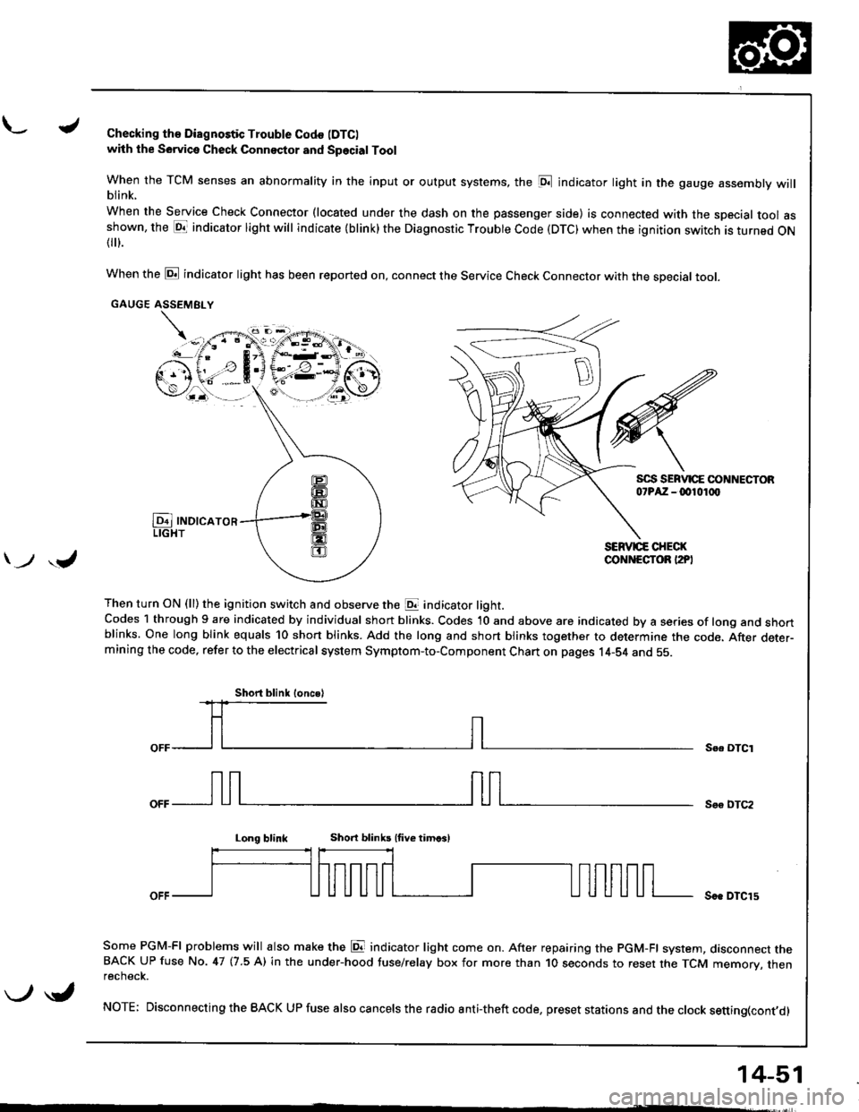
L./Checking th€ Diagnostic Trouble Codo (DTC)
with the Sowica Check Connector and Special Tool
When the TCM senses an abnormality in the input or output systems, the [D;l indicator light in the gauge assembly willblink.
When the Service Check Connector (located under the dash on the passenger side) is connected with the special tool asshown, the E1T indicator light will indicate (blink) the Diagnostic Troubte Code (DTC) when the ignition switch is turned ON{
}.
When the @ indicator light has been reported on, connect the Service Check Connector with the special toot.
GAUGE ASSEMEI.Y
Then turn ON (ll) the ignition switch and observe the E indicator light.Codes 1 through 9 are indicated by individual short blinks. Codes 1O and above are indicated by a series of long and shortblinks. One long blink equals 10 short blinks. Add the long and short blinks together to determine the code. After deter-mining the code, refer to the electrical system Symptom-to-Component Chart on pages 14-S4 and 55.
\-F;ii^r
) ,J
Se. OTCI
Soo DTC2
Long blinkShort blinb lfive timcsl
Soe DTCl5
Some PGM-FI problems will also make the E indicator light come on. After repairing the PGM-FI system, dasconnect theBACK UP fuse No. 47 (7.5 A) in the under-hood tuse/relay box for more than 1O seconds to reset the TCM memory, thenrecnecK.
NOTE; Disconnecting the BACK UP fuse also cancels the radio anti-theft code, preset stations and the clock setting(cont,d)
Short blink loncsl
\-/ \i,
14-51
Page 470 of 1681
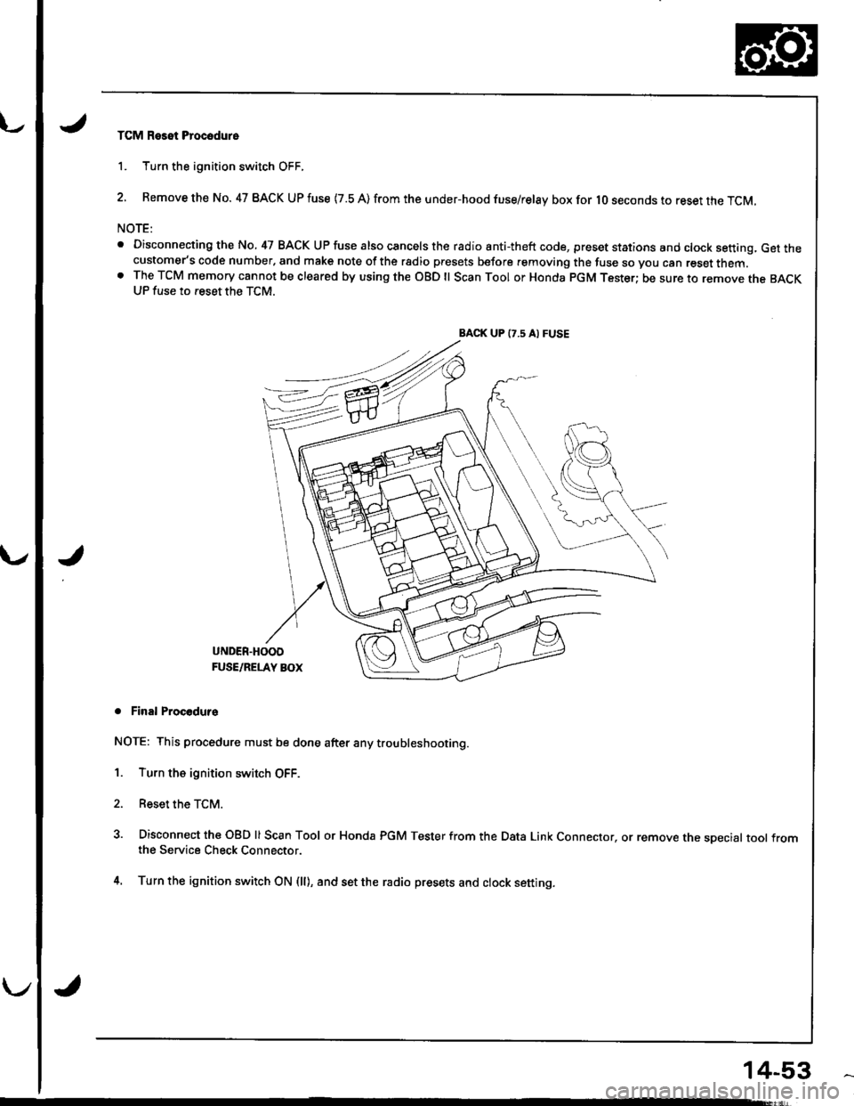
TCM Reset Procodure
1. Turn the ignition switch OFF.
2. Remove the No. 47 BACK UP fuse {7.8 A) from the under-hood fuse/relay box for lO seconds to reset the TCM.
NOTE:
. Disconnecting the No, 47 BACK UP fuse also cancels the radio anti-theft code, preset stations and clock setting, Get thecustomer's code number, and make note of the rsdio presets before removing the fuse so you can reset them.o The TCM memory cannot be cleared by using the OBD ll Scan Tool or Honda pGM Tester; be sure to remove the BACKUP fuse to reset the TCM.
BACK UP (7.5 A) FUSE
J
UNDER.HOOD
FUSE/RELAY BOX
. Final Procodurs
NOTE: This procedure must be done after any trou bleshooting.
1. Turn the ignition switch OFF.
2. Reset the TCM.
3. Disconnect the OBD ll Scan Tool or Honda PGM Tester from the Data Link Connector, or remove the sDecial tool fromthe Service Check Connector.
4. Turn the ignition switch ON (ll), and set the radio presets and clock setting.
14-53
Page 472 of 1681
u.drrf,,
J
J
J
14-55
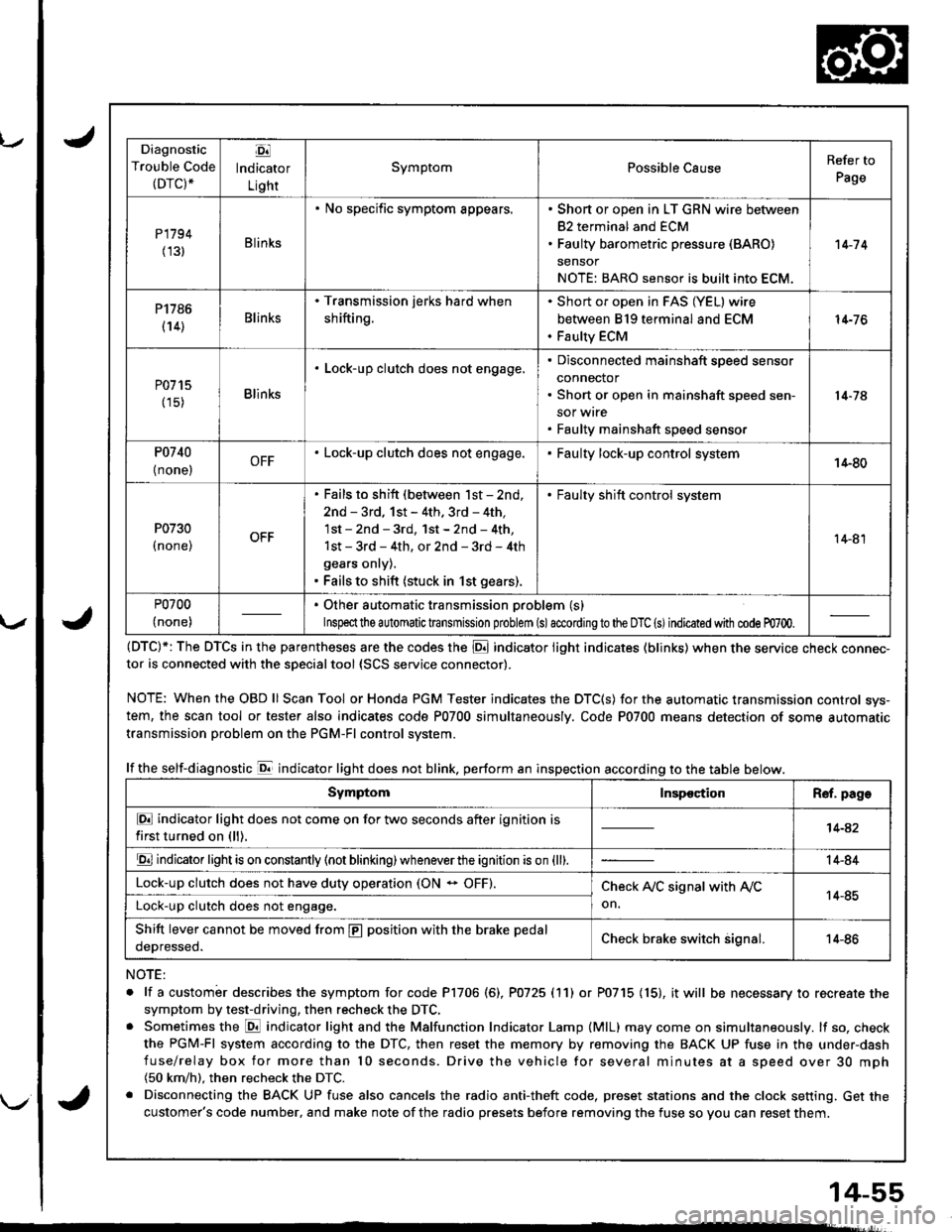
Diagnostic
Trouble Code(DTC).
Ej
lndicator
Light
SymptomPossible CauseRefer to
Page
P1794
(131Blinks
. No specific symptom appears.. Short or open in LT GRN wire between
82 terminal and ECM. Faulty barometric pressure (BARO)
sensor
NOTE: BARO sensor is built into ECM.
't 4-7 4
P1786
(14)Blinks
. Transmission jerks hard when
shifting.
Short or open in FAS (YEL) wire
between 819 terminal and ECM
Faulty ECM
14-76
P0715
(15)Blinks
. Lock-up clutch does not engage,Disconnected mainshaft speed sensor
connector
Short or open in mainshaft speed sen-
sor wrre
Faulty mainshaft speed senso.
14-74
P0740
{ none,OFF. Lock-up clutch does not engage.Faulty lock-up control system14-80
P0730
I none,
. Fails to shift (between lst - 2nd,
2nd - 3rd, 1st - 4th. 3rd - 4th,
1st - 2nd - 3rd, 1st - 2nd - 4th,
1st - 3rd - 4th, or 2nd - 3rd - 4th
gears onry).. Fails to shift (stuck in 1st gears).
. Faulty shift control system
14-81
P0700
(none)
. Other automatic transmission problem (s)
Inspeclthe a utomatic transmission problem (s)accordingto the DTC (s)indicated with code m700.
(DTC)*: The DTCS in the parentheses are the codes the E indicator light indicates (blinks) when the service cnecK connec-tor is connected with the sDecialtool {SCS service connector).
NOTE: WhentheOBDll Scan Tool orHonda PGM Tester indicates the DTC(S) for the automatic transmission control sys-
tem, the scan tool or tester also indicates code P0700 simultaneously. Code P0700 means detection of some automatic
transmission problem on the PGM-Fl control system.
lf the self-diagnostic E indicator light does not blink. perform an inspection according to the table below.
NOTE:
. lf a custombr describes the symptom for code P1706 (6), P0725 (11) or P0715 (15), it will be necessary to recreate the
symptom by test-driving, then recheck the DTC,. Sometimes the E indicator light and the Malfunction Indicator Lamp (MlL) may come on simultaneously. lf so, check
the PGM-Fl system according to the DTC, then reset the memory by removing the BACK UP fuse in the under-dash
fuse/relay box for more than l0 seconds. Drive the vehicle for several minutes at a speed over 30 mph(50 km/h). then recheck the DTC.
. Disconnecting the BACK UP fuse also cancels the radio anti-theft code, preset stations and the clock setting. Get the
customer's code number, and make note of the radio presets before removing the fuse so you can reset them.
SymptomInspectionR€f. page
E indicator light does not come on for two seconds after ignition is
first turned on (ll).14-42
E indicator light is on constantly (not blinking) wheneverthe ignition is on {ll).14-84
Lock-up clutch does not have duty operation (ON - OFF).Check A,/C signal with Ay'C
on.14-85Lock-up clutch does not engage.
Shift lever cannot be moved from E position with the brake pedal
oeDresseo.Check brake switch signal.14-86
Page 498 of 1681
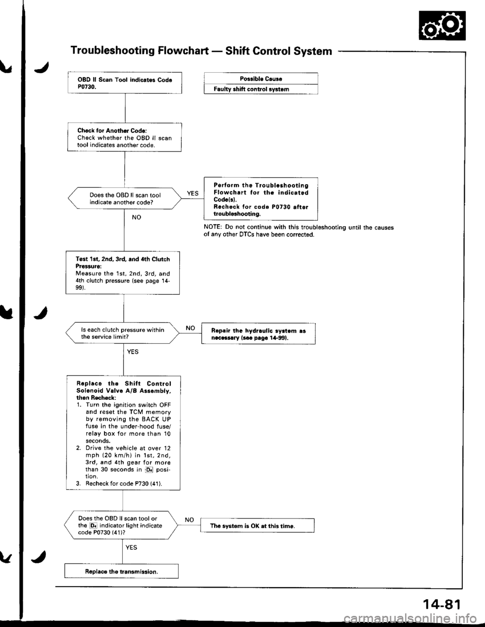
Troubleshooting Flowchart - Shaft Control System
NOTE: Do not continue with this troubleshootlng until the causesof any other DTCS have been corrected.
Chock foi Another Code:Check whether the OBD ll scantool indicates another code.
Psrtorm tho Tioubla3hootingFlowch.rt fo. th. indicatodCodcl.l.Rechsck tor code P0730 attoltroublolhooting.
Does the OBD ll scan toolindicate anothor code?
Tost 1st, 2nd, 3rd, and 4th ClutchProssuro:Measure the 1st,2nd,3rd, and4th clutch pressure (see page 14-
ls each clutch pressure withinthe service limit?R.p!ir lhG hydraulic ry3t.m ranac.3!.ry l3€e pago 1+991.
Roplace the Shilt ContiolSolonoid Valve A/B Assombly,thon Recheck:1. Turn the ignition switch OFFand reset the TCM memoryby removing the BACK UPfuse in the under-hood fuse/relay box for more than '10
seconds.2. Orive the vehicle at over 12mph (20 km/h) in lst,2nd,3rd, and 4th gear for morethan 30 seconds in E posi-tion.3, Recheck for code P730 (41).
Does the OBD llscan toolorthe E indicator light indicatecode P0730 (4'1)?Tho systom is OX etthi3 timo.
Poitible C.uBe
F""lty "hlft ".^t..t ",/"t".
Page 1342 of 1681
v
-t f--.l r --1 f-M.in cod. {11 S!b{od. (2}
oTcr2
-l F --{ FMain cod. (l) Sub-cod.11).--.Y-oTc r-rThnd'm6r.@6m
2
ON
light sl.ys on h ct36 or
Troubleshooting
Reading the DTC (cont'd)
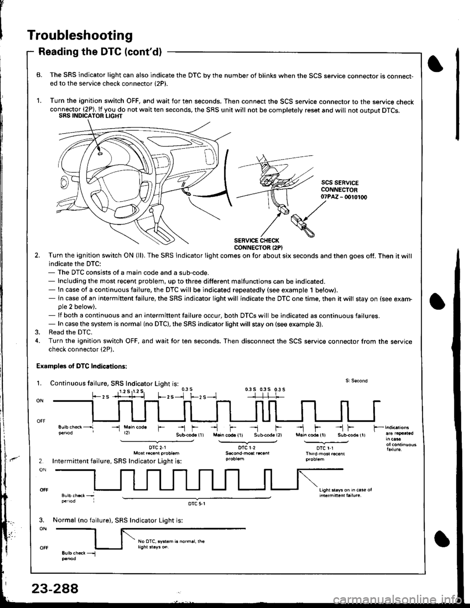
B. The SRS indicator light can also indicate the OTC by the number of blinks when the SCS service connector ts connect-ed to the service check connector (2P).
1. Turn the ignition switch OFF, and wait for ten seconds. Then connect the SCS service connector to the service checkconnector (2P). lf you do not wait ten seconds, the SRS unit will not be completelv reset and will not outout DTCS.SRS INDICATOR LIGHT
scs SERV|CECONI{ECTOR- (x)l01(x)
SERVICE CHECKCONNECTOR (2PI
2. Turn the ignition swilch ON (ll). The SRS indicator light comes on for about six seconds and then goes off. Then it will
indicate the DTC:- The DTC consists of a main code and a sub-code.- Including the most recent problem, up to three different malfunctions can be indicated.- ln case of a continuous failure, the DTC will be indicated repeatedly (see example 1 below).- In case of an intermiftent failure, the SRS indicator light will indicate the DTC one time. then it will stay on (see exarn-ple 2 beiow).- lf both a continuous and an intermittent failure occur, both DTCS will be indicated as continuous failures.- In case the system is normal (no DTC), the SRS indicator light will stay on {see example 3).
3. Read the DTC.
4. Turn the ignition switch OFF, and wait for ten seconds. Then disconnect the SCS service connector from the servicecheck connector (2P),
Examples ol DTC Indications:
L Continuous failure, SRS Indicator Light is:0.3 s 0.3s 0.3 s-]-]-l-t-
07?M
(S./'
\
-l Mlin cod. r
orc 2-1Mo3t r.cant probt.m
Intermittent failure, SRS Indicator Light is:
Normsl (no failure), SRS Indicator Light is:
oTc 5,r
Page 1502 of 1681
How the Circuit Works
The maintenance reminder light comes on to
remind the driver that the car is due for
scheduled mainlenance.
The maintenance reminder unit receives a vehicle
speed input from the vehicle speed sensor (VSS)
and uses this inlormation to compute the distance
traveled. For the first 6000 t 1 00 miles (9650 t 160
km) after the maintenance reminder light is reset, it
will come on for two seconds when you turn the
ignition switch to ON (ll) as a bulb check.
Between 6000 1 100 miles (9650 t 160 km) and
7500 t 100 miles (12070 I 160 km) the reminder
light will come on for two seconds when you turn
the ignition switch to ON (ll), and then flash for eight
seconds more.
Beyond 7500 t 100 miles (12070 t l60 km) the
reminder light will stay on when the ignition switch is
in the ON (ll) position until the unit is reset.
To reset the unit, the car must be parked and the
ignition switch in the ON (ll) position. Press the
reset button on the unit and hold it there for more
than three seconds, and the reminder light will
go off.
Refer to the Service Manual (Section 23, Electrical)
for specific tests or troubleshooting procedures.
83-1