Check system HONDA ODYSSEY 2016 RC1-RC2 / 5.G Quick Guide
[x] Cancel search | Manufacturer: HONDA, Model Year: 2016, Model line: ODYSSEY, Model: HONDA ODYSSEY 2016 RC1-RC2 / 5.GPages: 80, PDF Size: 16.28 MB
Page 45 of 80
82 || 83
INDEX
VOICE COMMAND
INDEX
CUSTOMER
INFORMATION
SPECIFICATIONS
MAINTENANCE
HANDLING THE UNEXPECTED
DRIVING
NAVIGATION
TABLE OF CONTENTS
VISUAL INDEX
SAFETY
INFORMATION
INSTRUMENT PANEL
VEHICLE
CONTROLS
AUDIO AND
CONNECTIVITY
BLUETOOTH®
HANDSFREELINK®
HONDALINK®
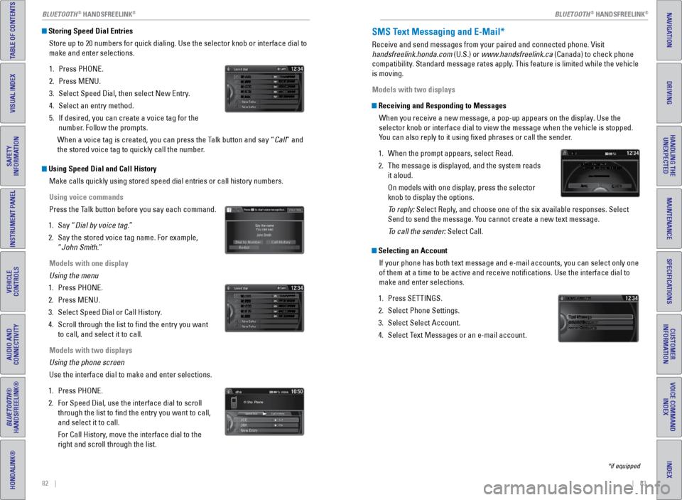
Storing Speed Dial Entries
Store up to 20 numbers for quick dialing. Use the selector knob or inter\
face dial to
make and enter selections.
1. Press PHONE.
2. Press MENU.
3. Select Speed Dial, then select New Entry.
4. Select an entry method.
5. If desired, you can create a voice tag for the
number. Follow the prompts.
When a voice tag is created, you can press the Talk button and say “Call” and
the stored voice tag to quickly call the number.
Using Speed Dial and Call History Make calls quickly using stored speed dial entries or call history numbe\
rs.
Using voice commands
Press the Talk button before you say each command.
1. Say “Dial by voice tag.”
2. Say the stored voice tag name. For example,
“John Smith.”
Models with one display
Using the menu
1. Press PHONE.
2. Press MENU.
3. Select Speed Dial or Call History.
4. Scroll through the list to find the entry you want
to call, and select it to call.
Models with two displays
Using the phone screen
Use the interface dial to make and enter selections.
1. Press PHONE.
2. For Speed Dial, use the interface dial to scroll
through the list to find the entry you want to call,
and select it to call.
For Call History, move the interface dial to the
right and scroll through the list.
SMS Text Messaging and E-Mail*
Receive and send messages from your paired and connected phone. Visit
handsfreelink.honda.com (U.S.) or www.handsfreelink.ca (Canada) to check phone
compatibility. Standard message rates apply. This feature is limited while the vehicle
is moving.
Models with two displays
Receiving and Responding to Messages
When you receive a new message, a pop-up appears on the display. Use the
selector knob or interface dial to view the message when the vehicle is \
stopped.
You can also reply to it using fixed phrases or call the sender.
1. When the prompt appears, select Read.
2. The message is displayed, and the system reads
it aloud.
On models with one display, press the selector
knob to display the options.
To reply: Select Reply, and choose one of the six available responses. Select
Send to send the message. You cannot create a new text message.
To call the sender: Select Call.
Selecting an Account
If your phone has both text message and e-mail accounts, you can select \
only one
of them at a time to be active and receive notifications. Use the inte\
rface dial to
make and enter selections.
1. Press SETTINGS.
2. Select Phone Settings.
3. Select Select Account.
4. Select Text Messages or an e-mail account.
*if equipped
Mr.AAA111AAA####
555EEE#### 444DDD#### 333CCC#### 222BBB####
Mr.EEE Mr.DDD Mr.CCC Mr.BBB
Mr.AAA111AAA####
555EEE#### 444DDD#### 333CCC#### 222BBB####
Mr.EEE Mr.DDD Mr.CCC Mr.BBB
BLUETOOTH® HANDSFREELINK®BLUETOOTH® HANDSFREELINK®
Page 51 of 80
94 || 95
DRIVING
DRIVING
INDEX
VOICE COMMAND
INDEX
CUSTOMER
INFORMATION
SPECIFICATIONS
MAINTENANCE
HANDLING THE UNEXPECTED
DRIVING
NAVIGATION
TABLE OF CONTENTS
VISUAL INDEX
SAFETY
INFORMATION
INSTRUMENT PANEL
VEHICLE
CONTROLS
AUDIO AND
CONNECTIVITY
BLUETOOTH®
HANDSFREELINK®
HONDALINK®
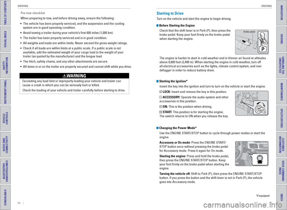
Starting the Ignition*
Insert the key into the ignition and turn to turn on the vehicle or star\
t the engine.
0 LOCK: Insert and remove the key in this position.
I ACCESSORY: Operate the audio system and other
accessories in this position.
II ON: This is the position when driving.
III START: This position is for starting the engine.
The switch returns to ON when you release the key.
Starting to Drive
Turn on the vehicle and start the engine to begin driving.
Before Starting the Engine
Check that the shift lever is in Park (P), then press the
brake pedal. Keep your foot firmly on the brake pedal
when starting the engine.
The engine is harder to start in cold weather and in thinner air found a\
t altitudes
above 8,000 feet (2,400 m). When starting the engine in cold weather, turn off
all electrical accessories such as the lights, climate control system, a\
nd rear
defogger in order to reduce battery drain.
*if equipped
Changing the Power Mode*Use the ENGINE START/STOP button to cycle through power modes or start the
engine.
Accessory or On mode: Press the ENGINE START/
STOP button once without pressing the brake pedal
for Accessory mode. Press it again for On mode.
Starting the engine: Press and hold the brake pedal,
then press the ENGINE START/STOP button. Keep
your foot firmly on the brake pedal when starting the
engine.
Turning the vehicle off: Shift to Park (P), then press the ENGINE START/STOP
button. If you press the button and the shift lever is not in Park (P)\
, the vehicle
goes into Accessory mode.
Brake pedal
Pre-tow checklist
When preparing to tow, and before driving away, ensure the following:
• The vehicle has been properly serviced, and the suspension and the cooli\
ng
system are in good operating condition.
• Avoid towing a trailer during your vehicle’s first 600 miles (1,000 km).
• The trailer has been properly serviced and is in good condition.
• All weights and loads are within limits. Never exceed the gross weight r\
atings.
• Check if all loads are within limits at a public scale. If a public scal\
e is not
available, add the estimated weight of your cargo load to the weight of \
your
trailer (as quoted by the manufacturer) and the tongue load.
• The hitch, safety chains, and any other attachments are secure.
• All items in or on the trailer are properly secured and cannot shift whi\
le you drive.
Exceeding any load limit or improperly loading your vehicle and trailer \
can
cause a crash in which you can be seriously hurt or killed.
Check the loading of your vehicle and trailer carefully before starting \
to driv
e.
WARNING
Page 53 of 80
98 || 99
DRIVING
DRIVING
INDEX
VOICE COMMAND
INDEX
CUSTOMER
INFORMATION
SPECIFICATIONS
MAINTENANCE
HANDLING THE UNEXPECTED
DRIVING
NAVIGATION
TABLE OF CONTENTS
VISUAL INDEX
SAFETY
INFORMATION
INSTRUMENT PANEL
VEHICLE
CONTROLS
AUDIO AND
CONNECTIVITY
BLUETOOTH®
HANDSFREELINK®
HONDALINK®
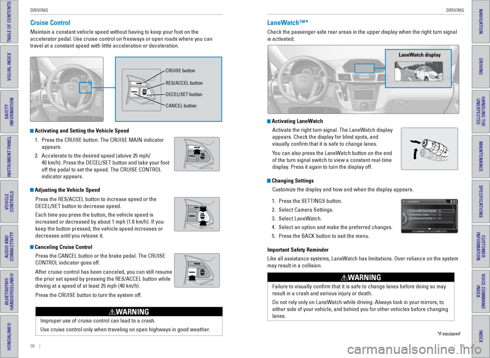
Cruise Control
Maintain a constant vehicle speed without having to keep your foot on th\
e
accelerator pedal. Use cruise control on freeways or open roads where yo\
u can
travel at a constant speed with little acceleration or deceleration.
Improper use of cruise control can lead to a crash.
Use cruise control only when traveling on open highways in good weather.
WARNING
Activating and Setting the Vehicle Speed1. Press the CRUISE button. The CRUISE MAIN indicator
appears.
2. Accelerate to the desired speed (above 25 mph/
40 km/h). Press the DECEL/SET button and take your foot
off the pedal to set the speed. The CRUISE CONTROL
indicator appears.
Adjusting the Vehicle Speed
Press the RES/ACCEL button to increase speed or the
DECEL/SET button to decrease speed.
Each time you press the button, the vehicle speed is
increased or decreased by about 1 mph (1.6 km/h). If you
keep the button pressed, the vehicle speed increases or
decreases until you release it.
Canceling Cruise ControlPress the CANCEL button or the brake pedal. The CRUISE
CONTROL indicator goes off.
After cruise control has been canceled, you can still resume
the prior set speed by pressing the RES/ACCEL button while
driving at a speed of at least 25 mph (40 km/h).
Press the CRUISE button to turn the system off.
CRUISE button
RES/ACCEL button
DECEL/SET button
CANCEL button
LaneWatch™*
Check the passenger-side rear areas in the upper display when the right turn signal
is activated.
Activating LaneWatchActivate the right turn signal. The LaneWatch display
appears. Check the display for blind spots, and
visually confirm that it is safe to change lanes.
You can also press the LaneWatch button on the end
of the turn signal switch to view a constant real-time
display. Press it again to turn the display off.
Changing SettingsCustomize the display and how and when the display appears.
1. Press the SETTINGS button.
2. Select Camera Settings.
3. Select LaneWatch.
4. Select an option and make the preferred changes.
5. Press the BACK button to exit the menu.
Important Safety Reminder
Like all assistance systems, LaneWatch has limitations. Over-reliance on the system
may result in a collision.
*if equipped
LaneWatch display
Failure to visually confirm that it is safe to change lanes before doi\
ng so may
result in a crash and serious injury or death.
Do not rely only on LaneWatch while driving. Always look in your mirrors, to
either side of your vehicle, and behind you for other vehicles before ch\
anging
lanes.
WARNING
Page 57 of 80
106 || 107
HANDLING THE UNEXPECTED
DRIVING
INDEX
VOICE COMMAND
INDEX
CUSTOMER
INFORMATION
SPECIFICATIONS
MAINTENANCE
HANDLING THE UNEXPECTED
DRIVING
NAVIGATION
TABLE OF CONTENTS
VISUAL INDEX
SAFETY
INFORMATION
INSTRUMENT PANEL
VEHICLE
CONTROLS
AUDIO AND
CONNECTIVITY
BLUETOOTH®
HANDSFREELINK®
HONDALINK®
Refueling
Use the proper fuel and refueling procedure to ensure the best performan\
ce and
safety of your vehicle.
Fuel Information
Use of unleaded gasoline of 87 octane or higher is recommended.
• Honda recommends TOP TIER Detergent Gasoline where available.
• Do NOT use gasoline containing more than 15% ethanol.
• Do NOT use gasoline containing methanol.
• Do NOT use gasoline containing MMT.
We recommend quality gasoline containing detergent additives that help
prevent fuel system and engine deposits. In addition, in order to mainta\
in good
performance, fuel economy, and emissions control, we strongly recommend the
use of gasoline that does NOT contain harmful manganese-based fuel addit\
ives
such as MMT, if such gasoline is available.
NOTICE
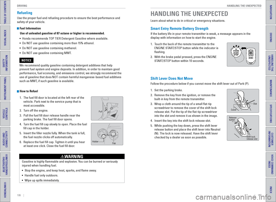
How to Refuel 1. The fuel fill door is located at the left rear of the
vehicle. Park next to the service pump that is
most accessible.
2. Turn off the engine.
3. Pull the fuel fill door release handle near the
parking brake. The fuel fill door opens.
4. Turn the fuel fill cap slowly to open. Place the fuel
fill cap in the holder.
5. Insert the filler nozzle fully. When the tank is full,
the fuel nozzle clicks off automatically.
6. Replace the fuel fill cap. Tighten it until you hear
at least one click. Close the fuel fill door.
Pull
Cap
Holder
Gasoline is highly flammable and explosive. You can be burned or seriously
injured when handling fuel.
•
Stop the engine, and keep heat, sparks, and flame away.
• Handle fuel only outdoors.
• Wipe up spills immediately.
WARNING
Learn about what to do in critical or emergency situations.
Smart Entry Remote Battery Strength
If the battery life in your remote transmitter is weak, a message appear\
s in the
display with information on how to start the engine.
1. Touch the back of the remote transmitter to the
ENGINE START/STOP button while the indicator is
flashing.
2. With the brake pedal pressed, press the ENGINE
START/STOP button within 10 seconds.
HANDLING THE UNEXPECTED
Shift Lever Does Not Move
Follow the procedure below if you cannot move the shift lever out of Par\
k (P).
1. Set the parking brake.
2. Remove the key from the ignition, or remove the
built-in key from the remote transmitter.
3. Wrap a cloth around the tip of a small flat-tip
screwdriver to remove the cover of the shift lock
release slot. Put the tip of the flat-tip screwdriver
into the slot and remove it as shown in the image.
4. Insert the key into the shift lock release slot.
5. While pushing the key down, press the shift lever
release button and place the shift lever into Neutral
(N). The lock is now released. Have the shift lever
checked by a dealer as soon as possible.
Slot
Cover
Release
button
Shift lock
release slot
Page 58 of 80
108 || 109
HANDLING THE UNEXPECTED
HANDLING THE UNEXPECTED
INDEX
VOICE COMMAND
INDEX
CUSTOMER
INFORMATION
SPECIFICATIONS
MAINTENANCE
HANDLING THE UNEXPECTED
DRIVING
NAVIGATION
TABLE OF CONTENTS
VISUAL INDEX
SAFETY
INFORMATION
INSTRUMENT PANEL
VEHICLE
CONTROLS
AUDIO AND
CONNECTIVITY
BLUETOOTH®
HANDSFREELINK®
HONDALINK®
After the Engine Starts
Once your vehicle’s engine has started, remove the jumper cables in the following
order:
1. Disconnect the jumper cable from your engine hanger.
2. Disconnect the other end of the jumper cable from the assisting vehicle’\
s (-)
terminal.
3. Disconnect the jumper cable from your vehicle’s (+) terminal.
4. Disconnect the other end of the jumper cable from the assisting vehicle’\
s (+)
terminal.
5. Have your vehicle inspected by a nearby service station or a dealer.
Overheating
If the temperature gauge needle is at the H mark, the engine suddenly lo\
ses power,
or steam or spray comes out from under the hood, your engine is overheat\
ing.
1. Immediately park the vehicle in a safe place. Turn
off all accessories and turn on the hazard warning
lights.
2. If steam or spray is not present: Keep the engine
running and open the hood.
If steam or spray is present: Turn off the engine and
wait until it subsides. Then, open the hood.
3. Check that the cooling fan is operating and stop the engine once the tem\
perature
gauge needle comes down. If the cooling fan is not operating, immediatel\
y stop
the engine.
4. Once the engine has cooled down, inspect the coolant level and check the\
cooling system components for leaks. If the coolant level in the reserve\
tank
is low, add coolant until it reaches the MAX mark. If there is no coolant in t\
he
reserve tank, make sure the radiator is cool, then cover the radiator ca\
p with a
heavy cloth and open the cap. If necessary, add coolant up to the base of the
filler neck, and put the cap back on.
5. Once the engine has cooled sufficiently, restart it and check the temperature
gauge. If the temperature needle has gone down, resume driving. If it ha\
s not
gone down, contact a dealer for repairs.
Steam and spray from an overheated engine can seriously scald you.
Do not open the hood if steam is coming out.
WARNING
Removing the radiator cap while the engine is hot can cause the coolant \
to
spray out, seriously scalding you.
Always let the engine and radiator cool down before removing the radiato\
r cap.
WARNING
Continuing to drive with the temperature gauge needle at the H mark may \
damage
the engine.
NOTICE
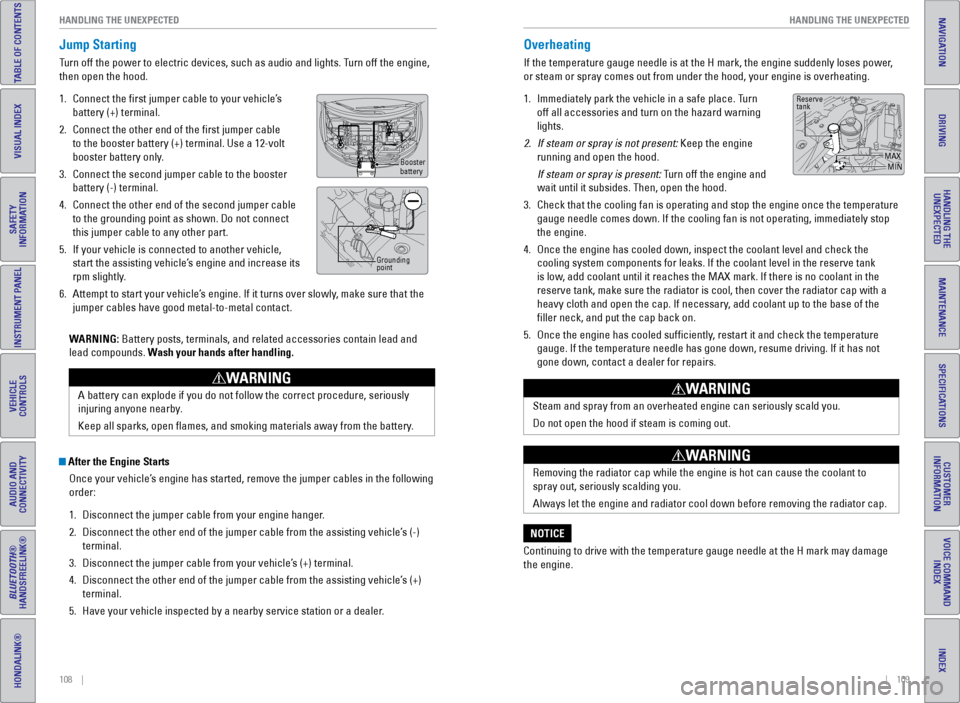
Reserve
tank
MAXMIN
Jump Starting
Turn off the power to electric devices, such as audio and lights. Turn off the engine,
then open the hood.
1. Connect the first jumper cable to your vehicle’s
battery (+) terminal.
2. Connect the other end of the first jumper cable
to the booster battery (+) terminal. Use a 12-volt
booster battery only.
3. Connect the second jumper cable to the booster
battery (-) terminal.
4. Connect the other end of the second jumper cable
to the grounding point as shown. Do not connect
this jumper cable to any other part.
5. If your vehicle is connected to another vehicle,
start the assisting vehicle’s engine and increase its
rpm slightly.
6. Attempt to start your vehicle’s engine. If it turns over slowly, make sure that the
jumper cables have good metal-to-metal contact.
WARNING: Battery posts, terminals, and related accessories contain lead and
lead compounds. Wash your hands after handling.
A battery can explode if you do not follow the correct procedure, seriou\
sly
injuring anyone nearby.
Keep all sparks, open flames, and smoking materials away from the batt\
ery.
WARNING
Booster
battery
Grounding
point
Page 59 of 80
110 || 111
HANDLING THE UNEXPECTED
HANDLING THE UNEXPECTED
INDEX
VOICE COMMAND
INDEX
CUSTOMER
INFORMATION
SPECIFICATIONS
MAINTENANCE
HANDLING THE UNEXPECTED
DRIVING
NAVIGATION
TABLE OF CONTENTS
VISUAL INDEX
SAFETY
INFORMATION
INSTRUMENT PANEL
VEHICLE
CONTROLS
AUDIO AND
CONNECTIVITY
BLUETOOTH®
HANDSFREELINK®
HONDALINK®
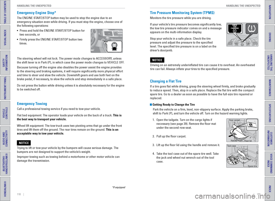
Emergency Engine Stop*
The ENGINE START/STOP button may be used to stop the engine due to an
emergency situation even while driving. If you must stop the engine, cho\
ose one of
the following operations:
• Press and hold the ENGINE START/STOP button for
two seconds, or
• Firmly press the ENGINE START/STOP button two
times.
Emergency Towing
Call a professional towing service if you need to tow your vehicle.
Flat bed equipment: The operator loads your vehicle on the back of a tru\
ck. This is
the best way to transport your vehicle.
Wheel lift equipment: The tow truck uses two pivoting arms that go under\
the front
tires and lift them off the ground. The rear tires remain on the ground.\
This is an
acceptable way to tow your vehicle.
Trying to lift or tow your vehicle by the bumpers will cause serious dama\
ge. The
bumpers are not designed to support the vehicle’s weight.
Improper towing such as towing behind a motorhome or other motor vehicle\
can
damage the transmission.
NOTICE
*if equipped
The steering wheel will not lock. The power mode changes to ACCESSORY, unless
the shift lever is in Park (P), in which case the power mode changes t\
o VEHICLE OFF.
Because turning off the engine also disables the power assist the engine\
provides
to the steering and braking systems, it will require significantly mor\
e physical effort
and time to steer and slow the vehicle. Downshift gears and use both fee\
t on the
brake pedal, if necessary, to slow the vehicle and stop immediately in a safe place.
Do not press the button while driving unless it is absolutely necessary \
for the engine
to be switched off. Driving on an extremely underinflated tire can cause it to overheat. A\
n overheated
tire can fail. Always inflate your tires to the specified pressure.NOTICE
Tire Pressure Monitoring System (TPMS)
Monitors the tire pressure while you are driving.
If your vehicle’s tire pressure becomes significantly low,
the low tire pressure indicator comes on and a message
appears on the multi-information display.
Stop your vehicle in a safe place. Check the tire
pressure and adjust the pressure to the specified
level. The specified tire pressure is on a label on the
driver’s doorjamb.
Changing a Flat Tire
If a tire goes flat while driving, grasp the steering wheel firmly, and brake gradually
to reduce speed. Then, stop in a safe place. Replace the flat tire wit\
h the compact
spare tire. Go to a dealer as soon as possible to have the full-size tir\
e repaired or
replaced.
Getting Ready to Change the Tire
Park the vehicle on a firm, level, non-slippery surface. Apply the par\
king brake,
shift to Park (P), and turn the vehicle off. Turn on the hazard warning lights.
1. Open the tailgate. Turn on the cargo lights if
necessary (see page 39). Remove the floor mat
under the second-row seat.
2. Pull up the floor carpet.
3. Lift up the floor lid using the handle and remove it.
4. Take the tool case out of the spare tire well. Take
the jack and wheel nut wrench out of the tool
case.
Tool case
Spare tire
Floor carpet
Handle
Floor lid
Page 64 of 80
120 || 121
MAINTENANCE
HANDLING THE UNEXPECTED
INDEX
VOICE COMMAND
INDEX
CUSTOMER
INFORMATION
SPECIFICATIONS
MAINTENANCE
HANDLING THE UNEXPECTED
DRIVING
NAVIGATION
TABLE OF CONTENTS
VISUAL INDEX
SAFETY
INFORMATION
INSTRUMENT PANEL
VEHICLE
CONTROLS
AUDIO AND
CONNECTIVITY
BLUETOOTH®
HANDSFREELINK®
HONDALINK®
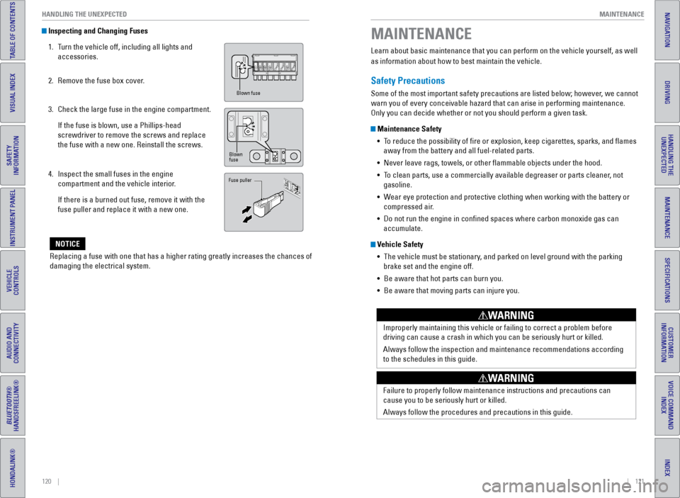
Inspecting and Changing Fuses
1. Turn the vehicle off, including all lights and
accessories.
2. Remove the fuse box cover.
3. Check the large fuse in the engine compartment.
If the fuse is blown, use a Phillips-head
screwdriver to remove the screws and replace
the fuse with a new one. Reinstall the screws.
4. Inspect the small fuses in the engine
compartment and the vehicle interior.
If there is a burned out fuse, remove it with the
fuse puller and replace it with a new one.
Replacing a fuse with one that has a higher rating greatly increases the\
chances of
damaging the electrical system.
NOTICE
Blown fuse
Blown
fuse
Fuse puller
Learn about basic maintenance that you can perform on the vehicle yourse\
lf, as well
as information about how to best maintain the vehicle.
Safety Precautions
Some of the most important safety precautions are listed below; however, we cannot
warn you of every conceivable hazard that can arise in performing mainte\
nance.
Only you can decide whether or not you should perform a given task.
Maintenance Safety • To reduce the possibility of fire or explosion, keep cigarettes, sparks\
, and flames
away from the battery and all fuel-related parts.
• Never leave rags, towels, or other flammable objects under the hood.
• To clean parts, use a commercially available degreaser or parts cleaner, not
gasoline.
• Wear eye protection and protective clothing when working with the battery\
or
compressed air.
• Do not run the engine in confined spaces where carbon monoxide gas can\
accumulate.
Vehicle Safety
• The vehicle must be stationary, and parked on level ground with the parking
brake set and the engine off.
• Be aware that hot parts can burn you.
• Be aware that moving parts can injure you.
Improperly maintaining this vehicle or failing to correct a problem befo\
re
driving can cause a crash in which you can be seriously hurt or killed. \
Always follow the inspection and maintenance recommendations according
to the schedules in this guide.
WARNING
Failure to properly follow maintenance instructions and precautions can \
cause you to be seriously hurt or killed.
Always follow the procedures and precautions in this guide.
WARNING
MAINTENANCE
Page 65 of 80
122 || 123
MAINTENANCE
MAINTENANCE
INDEX
VOICE COMMAND
INDEX
CUSTOMER
INFORMATION
SPECIFICATIONS
MAINTENANCE
HANDLING THE UNEXPECTED
DRIVING
NAVIGATION
TABLE OF CONTENTS
VISUAL INDEX
SAFETY
INFORMATION
INSTRUMENT PANEL
VEHICLE
CONTROLS
AUDIO AND
CONNECTIVITY
BLUETOOTH®
HANDSFREELINK®
HONDALINK®
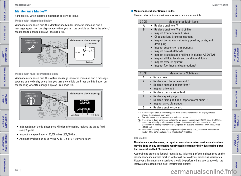
Maintenance Minder™
Reminds you when indicated maintenance service is due.
Models with information display
When maintenance is due, the Maintenance Minder indicator comes on and a\
message appears on the display every time you turn the vehicle on. Press\
the select/
reset knob to change displays (see page 28).
Maintenance
Minder indicator
Main items
Sub itemsMaintenance Minder message
Models with multi-information display
When maintenance is due, the system message indicator comes on and a mes\
sage
appears on the display every time you turn the vehicle on. Press the Inf\
o button on
the steering wheel to change displays (see page 29).
Maintenance
Minder indicator
Main items Sub items
Maintenance Minder message
• Independent of the Maintenance Minder information, replace the brake fl\
uid
every 3 years.
• Inspect idle speed every 160,000 miles (256,000 km).
• Adjust the valves during services A, B, 1, 2, or 3 if they are noisy. U.S. models
Maintenance, replacement, or repair of emissions control devices and sys\
tems
may be done by any automotive repair establishment or individuals using \
parts
that are certified to EPA standards.
According to state and federal regulations, failure to perform maintenan\
ce on the
maintenance main items marked with # will not void your emissions warranties.
However, all maintenance services should be performed in accordance with the
intervals indicated by the multi-information display.
Maintenance Minder Service Codes
These codes indicate what services are due on your vehicle.
*1: If a message SERVICE does not appear more than 12 months after the display is reset,
change the engine oil every year.
#: See information on maintenance and emissions warranty.
CODEMaintenance Main Items
A Replace engine oi l*1
BReplace engine oil*1 and oil �lter
Inspect front and rear brakes
Check parking brake adjustment
Inspect tie rod ends, steering gearbox, boots, and
drain plug
Inspect suspension components
Inspect driveshaft boots
Inspect brake hoses and lines (including ABS/VSA)
Inspect all �uid levels and condition of �uid s
Inspect exhaust system
#
Inspect fuel lines and connection s#
*2:If you drive in dusty conditions, replace the air cleaner element every \
15,000 miles (24,000 km).*3:If you drive primarily in urban areas that have high concentrations of i\
ndustrial soot an d
pollution from die sel-powered vehicles, replace the dust and pollen �lter every 15,000 \
mile s
(24,000 km ).
*4:If you drive regularly in very high temperatures (over 110°F, 43°\
C), in very low temperatures (under -20°F, -29°C), replace every 60,000 miles/100,000 km .
CODEMaintenance Sub Items
1 Rotate tires
• •
•
•
•
•
•
•
•
•
•
•
2Replace air cleaner element*2
Replace dust and pollen �lter*3
Inspect drive belt
3 Replace transmission �uid
4Replace spark plugs
Replace timing belt and inspect water pump*4
Inspect valve clearance
5 Replace engine coolan t
•
•
•
•
•
•
•
•
Page 67 of 80
126 || 127
MAINTENANCE
MAINTENANCE
INDEX
VOICE COMMAND
INDEX
CUSTOMER
INFORMATION
SPECIFICATIONS
MAINTENANCE
HANDLING THE UNEXPECTED
DRIVING
NAVIGATION
TABLE OF CONTENTS
VISUAL INDEX
SAFETY
INFORMATION
INSTRUMENT PANEL
VEHICLE
CONTROLS
AUDIO AND
CONNECTIVITY
BLUETOOTH®
HANDSFREELINK®
HONDALINK®
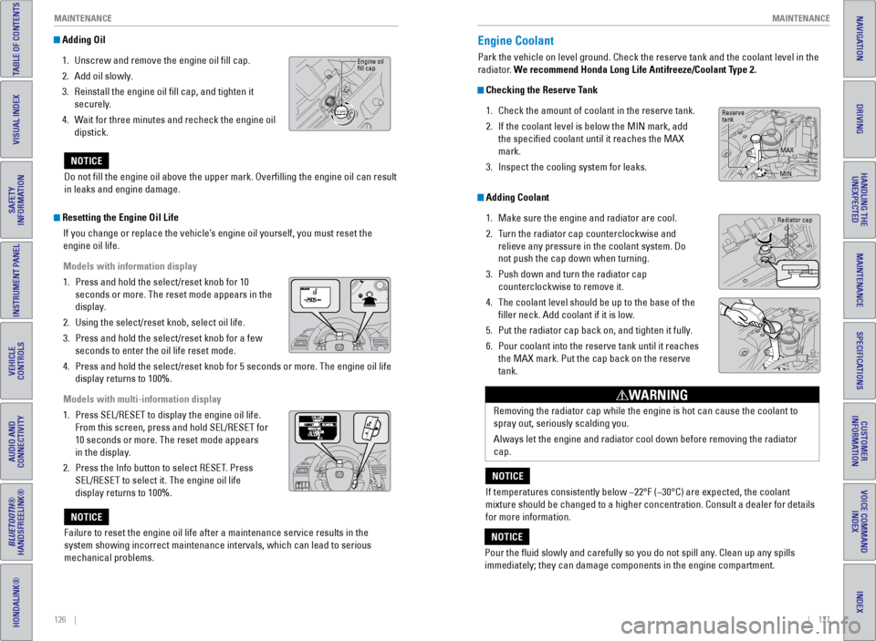
Adding Oil
1. Unscrew and remove the engine oil fill cap.
2. Add oil slowly.
3. Reinstall the engine oil fill cap, and tighten it
securely.
4. Wait for three minutes and recheck the engine oil
dipstick.
Do not fill the engine oil above the upper mark. Overfilling the eng\
ine oil can result
in leaks and engine damage.
NOTICE
Engine oil
fill cap
Resetting the Engine Oil Life If you change or replace the vehicle’s engine oil yourself, you must reset the
engine oil life.
Models with information display
1. Press and hold the select/reset knob for 10
seconds or more. The reset mode appears in the
display.
2. Using the select/reset knob, select oil life.
3. Press and hold the select/reset knob for a few
seconds to enter the oil life reset mode.
4. Press and hold the select/reset knob for 5 seconds or more. The engine o\
il life
display returns to 100%.
Models with multi-information display
1. Press SEL/RESET to display the engine oil life.
From this screen, press and hold SEL/RESET for
10 seconds or more. The reset mode appears
in the display.
2. Press the Info button to select RESET. Press
SEL/RESET to select it. The engine oil life
display returns to 100%.
Failure to reset the engine oil life after a maintenance service results\
in the
system showing incorrect maintenance intervals, which can lead to seriou\
s
mechanical problems.
NOTICE
Engine Coolant
Park the vehicle on level ground. Check the reserve tank and the coolant\
level in the
radiator. We recommend Honda Long Life Antifreeze/Coolant Type 2.
Checking the Reserve Tank 1. Check the amount of coolant in the reserve tank.
2. If the coolant level is below the MIN mark, add
the specified coolant until it reaches the MAX
mark.
3. Inspect the cooling system for leaks.
Adding Coolant
1. Make sure the engine and radiator are cool.
2. Turn the radiator cap counterclockwise and
relieve any pressure in the coolant system. Do
not push the cap down when turning.
3. Push down and turn the radiator cap
counterclockwise to remove it.
4. The coolant level should be up to the base of the
filler neck. Add coolant if it is low.
5. Put the radiator cap back on, and tighten it fully.
6. Pour coolant into the reserve tank until it reaches
the MAX mark. Put the cap back on the reserve
tank.
Removing the radiator cap while the engine is hot can cause the coolant \
to
spray out, seriously scalding you.
Always let the engine and radiator cool down before removing the radiato\
r
cap.
WARNING
If temperatures consistently below −22°F (−30°C) are expec\
ted, the coolant
mixture should be changed to a higher concentration. Consult a dealer fo\
r details
for more information.
NOTICE
Pour the fluid slowly and carefully so you do not spill any. Clean up any spills
immediately; they can damage components in the engine compartment.
NOTICE
Radiator cap
Reserve
tank MAX
MIN
Page 72 of 80
136 || 137
MAINTENANCE
MAINTENANCE
INDEX
VOICE COMMAND
INDEX
CUSTOMER
INFORMATION
SPECIFICATIONS
MAINTENANCE
HANDLING THE UNEXPECTED
DRIVING
NAVIGATION
TABLE OF CONTENTS
VISUAL INDEX
SAFETY
INFORMATION
INSTRUMENT PANEL
VEHICLE
CONTROLS
AUDIO AND
CONNECTIVITY
BLUETOOTH®
HANDSFREELINK®
HONDALINK®
Temperature
The temperature grades are A (the highest), B, and C, representing the\
tire’s
resistance to the generation of heat and its ability to dissipate heat w\
hen tested
under controlled conditions on a specified indoor laboratory test whee\
l. Sustained
high temperature can cause the material of the tire to degenerate and re\
duce
tire life, and excessive temperature can lead to sudden tire failure. Th\
e grade
C corresponds to a level of performance which all passenger car tires must
meet under the Federal Motor Vehicle Safety Standard No. 109. Grades B and
A represent higher levels of performance on the laboratory test wheel th\
an the
minimum required by law.
WARNING: The temperature grade for this tire is established for a tire that
is properly inflated and not overloaded. Excessive speed, underinfla\
tion, or
excessive loading, either separately or in combination, can cause heat b\
uildup
and possible tire failure.
Tire Pressure Monitoring System (TPMS) - Required Federal
Explanation
U.S. models only
Each tire, including the spare (if provided), should be checked monthl\
y
when cold and inflated to the inflation pressure recommended by the \
vehicle manufacturer on the vehicle placard or tire inflation pressure\
label.
(If your vehicle has tires of a different size than the size indicated \
on the
vehicle placard or tire inflation pressure label, you should determine\
the
proper tire inflation pressure for those tires.)
As an added safety feature, your vehicle has been equipped with
a tire pressure monitoring system (TPMS) that illuminates a low
tire pressure telltale when one or more of your tires is significantly\
under-inflated.
Accordingly, when the low tire pressure telltale illuminates, you should stop
and check your tires as soon as possible, and inflate them to the prop\
er
pressure.
Driving on a significantly under-inflated tire causes the tire to overheat and
can lead to tire failure. Under-inflation also reduces fuel efficiency and tire
tread life, and may affect the vehicle’s handling and stopping ability.
Please note that the TPMS is not a substitute for proper tire maintenanc\
e,
and it is the driver’s responsibility to maintain correct tire pressure, even if
under-inflation has not reached the level to trigger illumination of the TP\
MS
low tire pressure telltale.
Models with information display
Your vehicle has also been equipped with a TPMS malfunction
indicator to indicate when the system is not operating properly.
The TPMS malfunction indicator is provided by a separate telltale,
which displays the symbol “TPMS” when illuminated.
When the malfunction indicator is illuminated, the system may not be
able to detect low tire pressure as intended.
Models with multi-information display
Your vehicle has also been equipped with a TPMS malfunction indicator to \
indicate when the system is not operating properly. The TPMS malfunction
indicator is combined with the low tire pressure telltale. When the syst\
em
detects a malfunction, the telltale will flash for approximately one m\
inute
and then remain continuously illuminated. This sequence will continue up\
on
subsequent vehicle start-ups as long as the malfunction exists.
When the malfunction indicator is illuminated, the system may not be abl\
e
to detect or signal low tire pressure as intended.
TPMS malfunctions may occur for a variety of reasons, including the
installation of replacement or alternate tires or wheels on the vehicle \
that
prevent the TPMS from functioning properly.
Always check the TPMS malfunction telltale after replacing one or more
tires or wheels on your vehicle to ensure that the replacement or altern\
ate
tires and wheels allow the TPMS to continue to function properly.