steering wheel HONDA ODYSSEY 2018 (in English) Manual PDF
[x] Cancel search | Manufacturer: HONDA, Model Year: 2018, Model line: ODYSSEY, Model: HONDA ODYSSEY 2018Pages: 763, PDF Size: 47.02 MB
Page 612 of 763
610
uuBraking uCollision Mitigation Braking SystemTM (CMBSTM)*
Driving
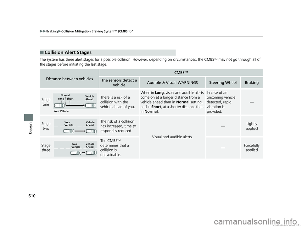
The system has three alert stages for a possible collision. However, depending on circumstances, the CMBSTM may not go through all of
the stages before initiating the last stage.
■Collision Alert Stages
Distance between vehicles
CMBSTM
The sensors detect a vehicleAudible & Visual WARNINGSSteering WheelBraking
Stage oneThere is a risk of a
collision with the
vehicle ahead of you.
When in Long , visual and audible alerts
come on at a longer distance from a
vehicle ahead than in Normal setting,
and in Short, at a shorter distance than
in Normal .In case of an
oncoming vehicle
detected, rapid
vibration is
provided.
—
Stage
twoThe risk of a collision
has increased, time to
respond is reduced.
Visual and audible alerts.
—Lightly
applied
Stage three
The CMBSTM
determines that a
collision is
unavoidable.
—Forcefully applied
Your Vehicle Vehicle
Ahead
Normal
Short
Long
Your
Vehicle Vehicle
Ahead
Your
VehicleVehicle
Ahead
18 US ODYSSEY-31THR6010.book 610 ページ 2018年12月6日 木曜日 午後4時18分
Page 630 of 763
628
Driving
Multi-View Rear Camera
About Your Multi-View Rear Camera
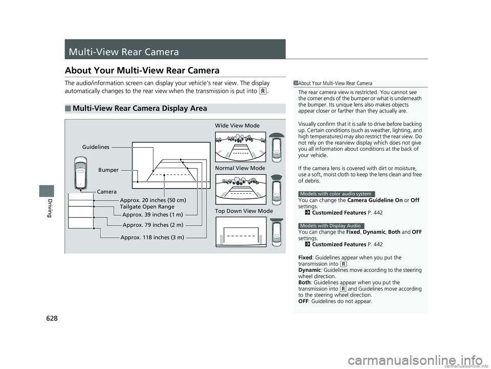
The audio/information screen can display your vehicle’s rear view. The display
automatically changes to the rear view when the transmission is put into
(R.
■Multi-View Rear Camera Display Area
1About Your Multi-View Rear Camera
The rear camera view is restricted. You cannot see
the corner ends of the bum per or what is underneath
the bumper. Its unique le ns also makes objects
appear closer or farther than they actually are.
Visually confirm that it is safe to drive before backing
up. Certain conditions (such as weather, lighting, and
high temperatures) may also re strict the rear view. Do
not rely on the rearview display which does not give
you all information about c onditions at the back of
your vehicle.
If the camera lens is cove red with dirt or moisture,
use a soft, moist cloth to keep the lens clean and free
of debris.
You can change the Camera Guideline On or Off
settings. 2 Customized Features P. 442
You can change the Fixed, Dynamic , Both and OFF
settings. 2 Customized Features P. 442
Fixed : Guidelines appear when you put the
transmission into
( R.
Dynamic : Guidelines move according to the steering
wheel direction.
Both : Guidelines appear when you put the
transmission into
( R and Guidelines move according
to the steering wheel direction.
OFF: Guidelines do not appear.
Models with color audio system
Models with Display Audio
Top Down View Mode Normal View Mode Wide View Mode
Guidelines
Bumper
Camera
Approx. 118 inches (3 m)Approx. 79 inches (2 m)
Approx. 39 inches (1 m)
Approx. 20 inches (50 cm)
Tailgate Open Range
18 US ODYSSEY-31THR6010.book 628 ページ 2018年12月6日 木曜日 午後4時18分
Page 663 of 763
661
uuReplacing Light Bulbs uFog Light Bulbs*
Maintenance
Fog Light Bulbs*
When replacing, use the following bulbs.
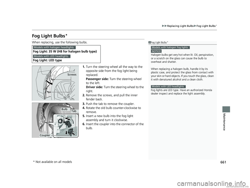
1.Turn the steering wheel all the way to the
opposite side from the fog light being
replaced.
Passenger side: Turn the steering wheel
to the left.
Driver side: Turn the steering wheel to the
right.
2. Remove the screws, and pull the inner
fender back.
3. Push the tab to remove the coupler.
4. Rotate the old bulb counter-clockwise to
remove.
5. Insert a new bulb into the fog light
assembly and turn it clockwise.
6. Insert the coupler into the connector of the
bulb.
Fog Light: 35 W (H8 for halogen bulb type)
Fog Light: LED type
1 Fog Light Bulbs*
NOTICE
Halogen bulbs get very hot wh en lit. Oil, perspiration,
or a scratch on the glass can cause the bulb to
overheat and shatter.
When replacing a halogen bulb, handle it by its
plastic case, and protect th e glass from contact with
your skin or hard objects. If you touch the glass, clean
it with denatured alc ohol and a clean cloth.
Fog lights are LED type. Ha ve an authorized Honda
dealer inspect and replace the light assembly.
Models with halogen fog lights
Models with LED headlights
Models with halogen headlights
Models with LED headlights
Screws
Bulb
Coupler
Tab
* Not available on all models
18 US ODYSSEY-31THR6010.book 661 ページ 2018年12月6日 木曜日 午後4時18分
Page 665 of 763
663
uuReplacing Light Bulbs uFront Turn Signal/Parking* Light Bulbs
Maintenance
Front Turn Signal/Parking* Light Bulbs
When replacing, use the following bulbs.
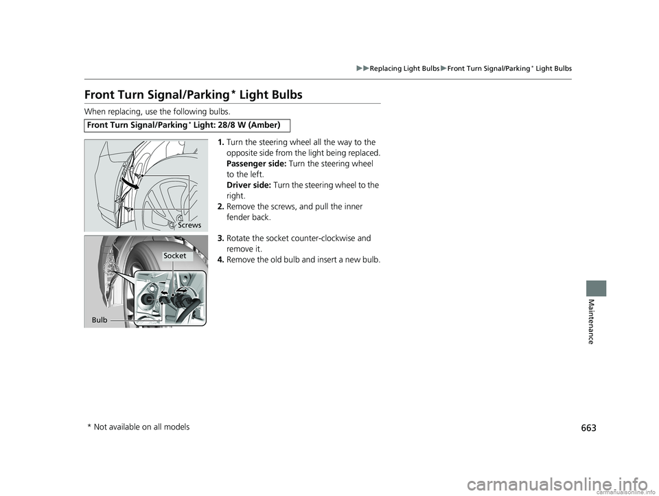
1.Turn the steering wheel all the way to the
opposite side from the light being replaced.
Passenger side: Turn the steering wheel
to the left.
Driver side: Turn the steering wheel to the
right.
2. Remove the screws, and pull the inner
fender back.
3. Rotate the socket counter-clockwise and
remove it.
4. Remove the old bulb and insert a new bulb.
Front Turn Signal/Parking* Light: 28/8 W (Amber)
Screws
Bulb
Socket
* Not available on all models
18 US ODYSSEY-31THR6010.book 663 ページ 2018年12月6日 木曜日 午後4時18分
Page 666 of 763
664
uuReplacing Light Bulbs uFront Side Marker Light Bulbs
Maintenance
Front Side Marker Light Bulbs
When replacing, use the following bulb.
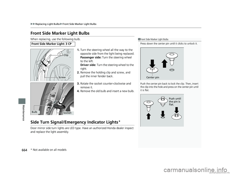
1.Turn the steering wheel all the way to the
opposite side from the light being replaced.
Passenger side: Turn the steering wheel
to the left.
Driver side: Turn the steering wheel to the
right.
2. Remove the holding clip and screw, and
pull the inner fender back.
3. Rotate the socket co unter-clockwise and
remove it.
4. Remove the old bulb and insert a new bulb.
Side Turn Signal/Emergency Indicator Lights*
Door mirror side turn lights are LED type. Have an authorized Honda dealer inspect
and replace the light assembly.
Front Side Marker Light: 3 CP
1 Front Side Marker Light Bulbs
Press down the center pin until it clicks to unlock it.
Push the center pin back to lock the clip. Then, insert
the clip into the hole and press on the center pin until
it is flat.
Center pin
Push until
the pin is
flat.
Clip
Screw
SocketBulb
* Not available on all models
18 US ODYSSEY-31THR6010.book 664 ページ 2018年12月6日 木曜日 午後4時18分
Page 683 of 763
681
uuChecking and Maintaining Tires uWinter Tires
Maintenance
Winter Tires
If driving on snowy or frozen roads, mount all season marked M+S tires, snow tires,
or tire chains; reduce speed; and maintain sufficient distance between vehicles when
driving.
Be particularly careful wh en operating the steering wheel or brakes to prevent
skidding.
Use tire chains, snow tires, or all season tires when necessary or according to the
law.
When mounting, refer to the following points.
For winter tires:
• Select the size and load ranges that are the same as the original tires.
• Mount the tires to all four wheels.
For tire chains:
• Install them on the front tires only.
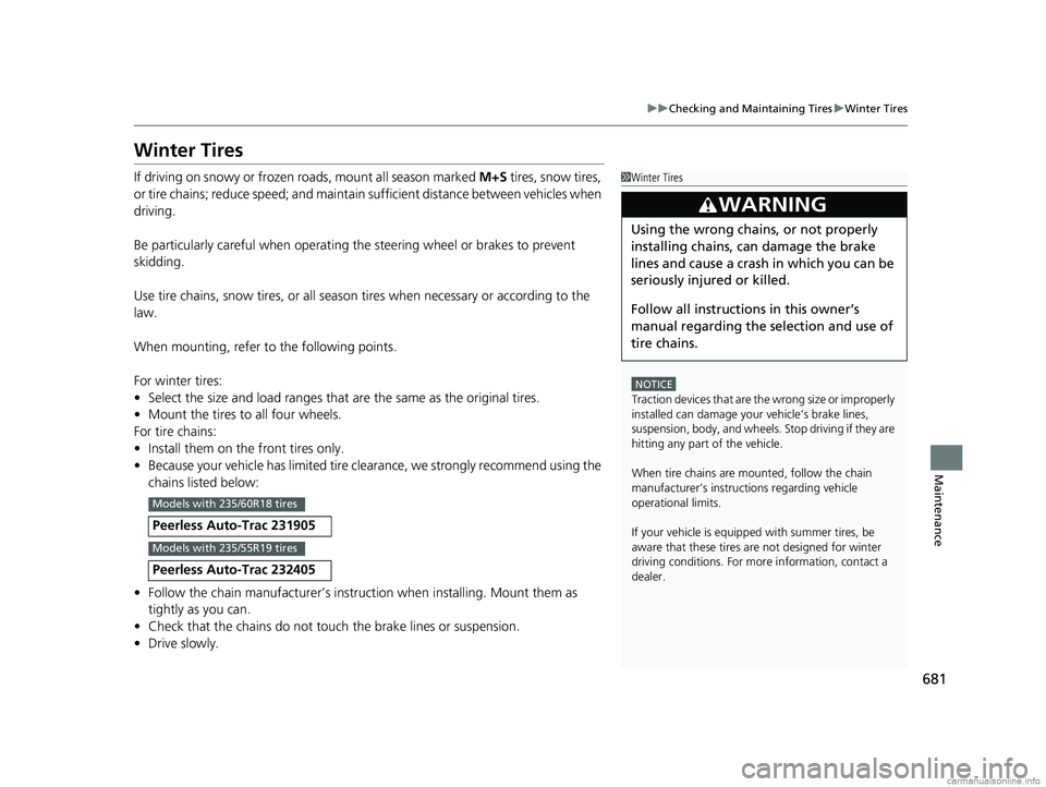
• Because your vehicle has limited tire clea rance, we strongly recommend using the
chains listed below:
• Follow the chain manufactur er’s instruction when installing. Mount them as
tightly as you can.
• Check that the chains do not touch the brake lines or suspension.
• Drive slowly.
Peerless Auto-Trac 231905
Peerless Auto-Trac 232405
1Winter Tires
NOTICE
Traction devices that are th e wrong size or improperly
installed can damage your vehicle’s brake lines,
suspension, body, and wheels. Stop driving if they are
hitting any part of the vehicle.
When tire chains are mounted, follow the chain
manufacturer’s instructi ons regarding vehicle
operational limits.
If your vehicle is equipp ed with summer tires, be
aware that these tires are not designed for winter
driving conditions. For more information, contact a
dealer.
3WARNING
Using the wrong chains, or not properly
installing chains, can damage the brake
lines and cause a crash in which you can be
seriously injured or killed.
Follow all instruction s in this owner’s
manual regarding the selection and use of
tire chains.
Models with 235/60R18 tires
Models with 235/55R19 tires
18 US ODYSSEY-31THR6010.book 681 ページ 2018年12月6日 木曜日 午後4時18分
Page 701 of 763
699Continued
Handling the Unexpected
If a Tire Goes Flat
Changing a Flat Tire
If a tire goes flat while driving, grasp the steering wheel firmly, and brake gradually
to reduce speed. Then, stop in a safe plac e. Replace the flat tire with a compact
spare tire. Go to a dealer as soon as possib le to have the full-size tire repaired or
replaced.
1. Park the vehicle on a firm, level, non-slippery surface and apply the parking brake.
2. Press the
(P button.
3. Turn on the hazard warning lights an d set the power mode to VEHICLE OFF.
1Changing a Flat Tire
Follow compact spare precautions:
Periodically check the tire pressure of the compact
spare. It should be set to the specified pressure.
Specified Pressure: 60 psi (420 kPa, 4.2 kgf/cm
2)
When driving with the compact spare tire, keep the
vehicle speed under 50 mph (80 km/h). Replace with
a full-size tire as soon as possible.
The compact spare tire and wheel in your vehicle are
specifically for this model. Do not use them with
another vehicle. Do not us e another type of compact
spare tire or wheel with your vehicle.
Do not mount tire chains on a compact spare tire.
If a chain-mounted front tire goes flat, remove one of
the full-size rear tires and replace it with the compact
spare tire. Remove the flat front tire and replace it
with the full-size tire that was removed from the rear.
Mount the tire chains on the front tire.
Do not use a puncture-repairi ng agent on a flat tire,
as it can damage the tire pressure sensor.
Do not use the jack if it doesn’t work properly. Call
your dealer or a prof essional towing service.
18 US ODYSSEY-31THR6010.book 699 ページ 2018年12月6日 木曜日 午後4時18分
Page 712 of 763
710
uuEngine Does Not Start uEmergency Engine Stop
Handling the Unexpected
Emergency Engine Stop
The ENGINE START/STOP button may be used to st op the engine due to an
emergency situation even while driving. If you must stop the engine, do either of the
following operations:
• Press and hold the ENGINE START/STOP button for about two seconds.
• Firmly press the ENGINE START/STOP button three times.
The steering wheel will not lock. However, because turning off the engine disables
the power assist the engine provides to the steering and braking systems, it will
require significantly more physical effort an d time to steer and slow the vehicle. Use
both feet on the brake pedal to slow down the vehicle and stop immediately in a
safe place.
The gear position auto matically changes to
(P after the vehicle comes to a complete
stop.
Then, the power mode changes to VEHICLE OFF.
Then press the ENGINE START/STOP button twice without depressing the brake
pedal to change the mode to VEHICLE OFF.
1 Emergency Engine Stop
Do not press the button while driving unless it is
absolutely necessary for the engine to be turned off.
U.S. models
Canadian models
18 US ODYSSEY-31THR6010.book 710 ページ 2018年12月6日 木曜日 午後4時18分
Page 722 of 763
720
uuIndicator, Coming On/Blinking uIf the Electric Power Steering (EPS) System Indicator Comes On
Handling the Unexpected
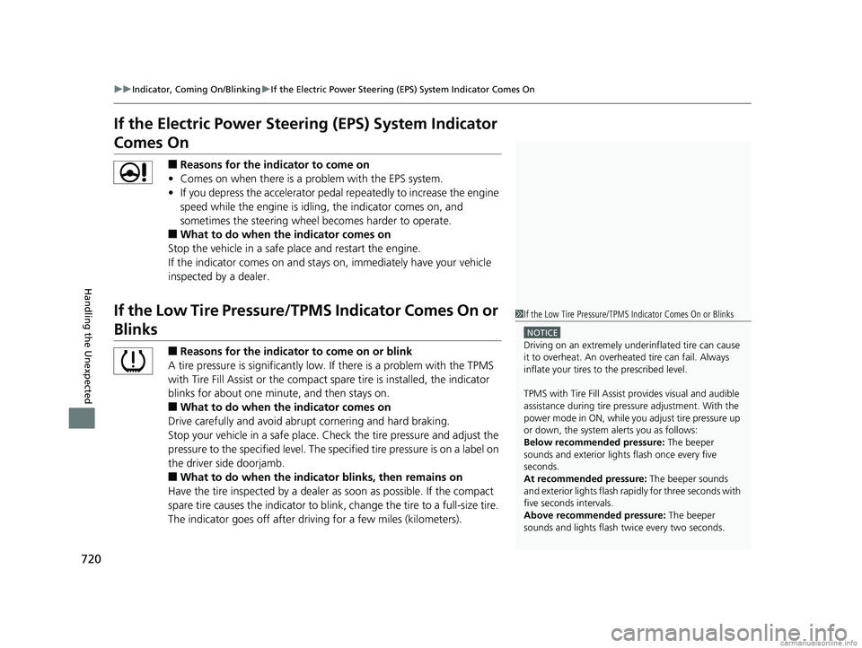
If the Electric Power Steeri ng (EPS) System Indicator
Comes On
■Reasons for the indicator to come on
• Comes on when there is a problem with the EPS system.
• If you depress the accelerator pedal repeatedly to increase the engine
speed while the engine is idling, the indicator comes on, and
sometimes the steering wheel becomes harder to operate.
■What to do when the indicator comes on
Stop the vehicle in a safe place and restart the engine.
If the indicator comes on and stays on, immediately have your vehicle
inspected by a dealer.
If the Low Tire Pressure/TPMS Indicator Comes On or
Blinks
■Reasons for the indicator to come on or blink
A tire pressure is significantly low. If there is a problem with the TPMS
with Tire Fill Assist or the compact spare tire is installed, the indicator
blinks for about one mi nute, and then stays on.
■What to do when the indicator comes on
Drive carefully and avoid abrupt cornering and hard braking.
Stop your vehicle in a safe place. Ch eck the tire pressure and adjust the
pressure to the specified level. The sp ecified tire pressure is on a label on
the driver side doorjamb.
■What to do when the indicator blinks, then remains on
Have the tire inspected by a dealer as soon as possible. If the compact
spare tire causes the indicator to blink, change the tire to a full-size tire.
The indicator goes off after driv ing for a few miles (kilometers).
1If the Low Tire Pressure/TPMS Indicator Comes On or Blinks
NOTICE
Driving on an extremely unde rinflated tire can cause
it to overheat. An overheated tire can fail. Always
inflate your tires to the prescribed level.
TPMS with Tire Fill Assist provides visual and audible
assistance during tire pre ssure adjustment. With the
power mode in ON, while y ou adjust tire pressure up
or down, the system alerts you as follows:
Below recommended pressure: The beeper
sounds and exterior lights flash once every five
seconds.
At recommended pressure: The beeper sounds
and exterior lights flash rapi dly for three seconds with
five seconds intervals.
Above recommended pressure: The beeper
sounds and lights flash tw ice every two seconds.
18 US ODYSSEY-31THR6010.book 720 ページ 2018年12月6日 木曜日 午後4時18分
Page 726 of 763
724
uuFuses uFuse Locations
Handling the Unexpected
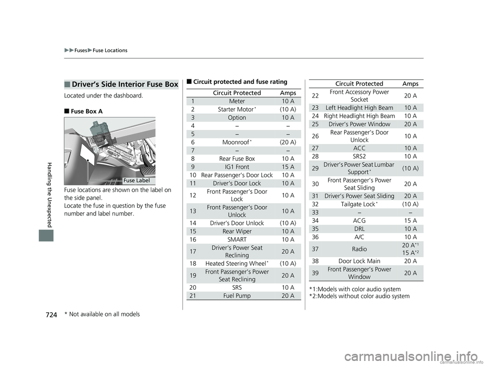
Located under the dashboard.
■Fuse Box A
Fuse locations are shown on the label on
the side panel.
Locate the fuse in question by the fuse
number and label number.
■Driver’s Side Interior Fuse Box
Fuse Label
■Circuit protected and fuse rating
Circuit ProtectedAmps
1Meter10 A
2Starter Motor*(10 A)
3Option10 A
4−−
5−−
6Moonroof*(20 A)
7−−
8Rear Fuse Box10 A
9IG1 Front15 A
10 Rear Passenger’s Door Lock 10 A
11Driver’s Door Lock10 A
12 Front Passenger’s Door
Lock 10 A
13Front Passenger’s Door
Unlock10 A
14 Driver’s Door Unlock (10 A)
15Rear Wiper10 A
16 SMART 10 A
17Driver’s Power Seat Reclining20 A
18 Heated Steering Wheel
*(10 A)
19Front Passenger’s Power Seat Reclining20 A
20 SRS 10 A
21Fuel Pump20 A*1:Models with color audio system
*2:Models without color audio system22
Front Accessory Power
Socket 20 A
23Left Headlight High Beam10 A
24 Right Headlight High Beam 10 A
25Driver’s Power Window20 A
26 Rear Passenger’s Door
Unlock 10 A
27ACC10 A
28 SRS2 10 A
29Driver’s Power Seat Lumbar Support*(10 A)
30 Front Passenger’s Power
Seat Sliding 20 A
31Driver’s Power Seat Sliding20 A
32 Tailgate Lock*(10 A)
33−−
34 ACG 15 A
35DRL10 A
36 A/C 10 A
37Radio20 A*1
15 A*2
38 Door Lock Main 20 A
39Front Passenger’s Power Window20 A
Circuit ProtectedAmps
* Not available on all models
18 US ODYSSEY-31THR6010.book 724 ページ 2018年12月6日 木曜日 午後4時18分