Hyundai Accent 2013 Owner's Manual
Manufacturer: HYUNDAI, Model Year: 2013, Model line: Accent, Model: Hyundai Accent 2013Pages: 402, PDF Size: 8.49 MB
Page 371 of 402
Maintenance
80 7
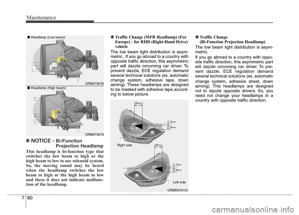
✽NOTICE - Bi-Function
Projection Headlamp
This headlamp is bi-function type that
switches the low beam to high or the
high beam to low to use solenoid system.
So, the moving sound may be heard
when the headlamp switches the low
beam to high or the high beam to low
and these it does not indicate malfunc-
tion of the headlamp.
❈Traffic Change (MFR Headlamp) (For
Europe) - for RHD (Right-Hand Drive)
vehicle
The low beam light distribution is asym-
metric. If you go abroad to a country with
opposite traffic direction, this asymmetric
part will dazzle oncoming car driver. To
prevent dazzle, ECE regulation demand
several technical solutions (ex. automatic
change system, adhesive tape, down
aiming). These headlamps are designed
to be masked with adhesive tape accord-
ing to below picture.❈Traffic Change
(Bi-Function Projection Headlamp)
The low beam light distribution is asym-
metric.
If you go abroad to a country with oppo-
site traffic direction, this asymmetric part
will dazzle oncoming car driver. To pre-
vent dazzle, ECE regulation demand
several technical solutions (ex. automatic
change system, adhesive sheet, down
aiming). This headlamps are designed
not to dazzle opposite drivers. So, you
need not change your headlamps in a
country with opposite traffic direction.
60mm
30mm
10mm
30mm
10mm
60mm
ORBR070101 Right side
Left side
ORB073078
ORB073079 ■Headlamp (Low beam)
■Headlamp (High beam)
Page 372 of 402
781
Maintenance
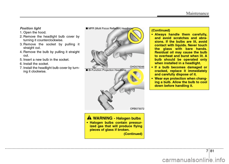
Position light
1. Open the hood.
2. Remove the headlight bulb cover by
turning it counterclockwise.
3. Remove the socket by pulling it
straight out.
4. Remove the bulb by pulling it straight
out.
5. Insert a new bulb in the socket.
6. Install the socket.
7. Install the headlight bulb cover by turn-
ing it clockwise.
WARNING- Halogen bulbs
• Halogen bulbs contain pressur-
ized gas that will produce flying
pieces of glass if broken.
(Continued)
OHD076046
ORB073072 ■MFR (Multi Focus Reflector) Headlamp
■Bi-Function Projection Headlamp
(Continued)
• Always handle them carefully,
and avoid scratches and abra-
sions. If the bulbs are lit, avoid
contact with liquids. Never touch
the glass with bare hands.
Residual oil may cause the bulb
to overheat and burst when lit. A
bulb should be operated only
when installed in a headlight.
• If a bulb becomes damaged or
cracked, replace it immediately
and carefully dispose of it.
• Wear eye protection when chang-
ing a bulb. Allow the bulb to cool
down before handling it.
Page 373 of 402
Maintenance
82 7
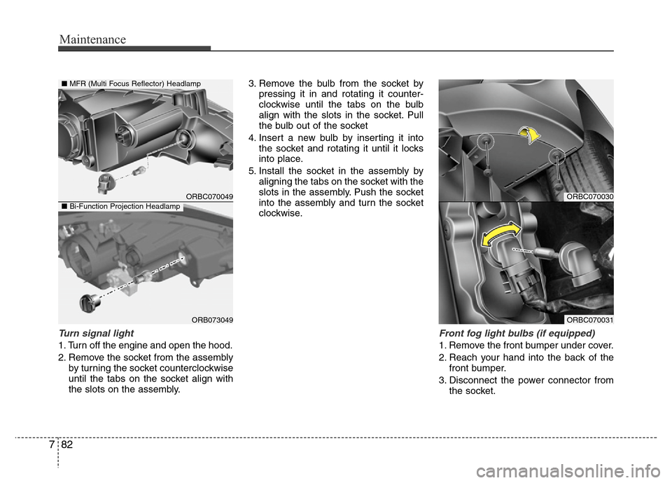
Turn signal light
1. Turn off the engine and open the hood.
2. Remove the socket from the assembly
by turning the socket counterclockwise
until the tabs on the socket align with
the slots on the assembly.3. Remove the bulb from the socket by
pressing it in and rotating it counter-
clockwise until the tabs on the bulb
align with the slots in the socket. Pull
the bulb out of the socket
4. Insert a new bulb by inserting it into
the socket and rotating it until it locks
into place.
5. Install the socket in the assembly by
aligning the tabs on the socket with the
slots in the assembly. Push the socket
into the assembly and turn the socket
clockwise.
Front fog light bulbs (if equipped)
1. Remove the front bumper under cover.
2. Reach your hand into the back of the
front bumper.
3. Disconnect the power connector from
the socket.
ORBC070030
ORBC070031
ORBC070049
ORB073049
■MFR (Multi Focus Reflector) Headlamp
■Bi-Function Projection Headlamp
Page 374 of 402
783
Maintenance
4. Remove the bulb-socket from the
housing by turning the socket counter
clockwise until the tabs on the socket
align with the slots on the housing.
5. Install the new bulb-socket into the
housing by aligning the tabs on the
socket with the slots in the housing.
Push the socket into the housing and
turn the socket clockwise.
6. Connect the power connector to the
socket.
7. Reinstall the front bumper under cover.
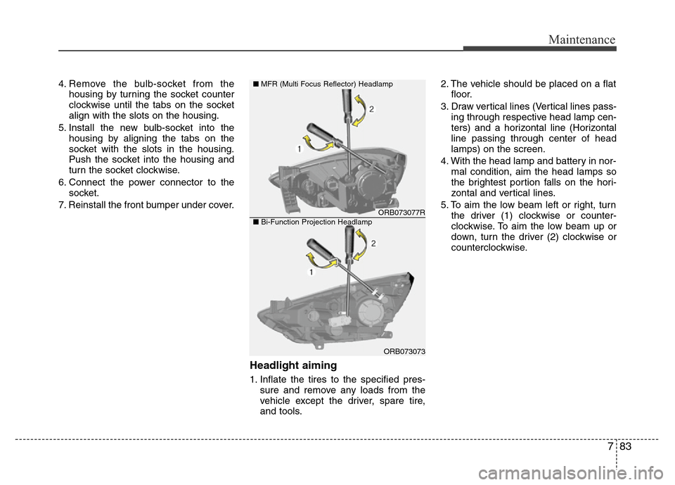
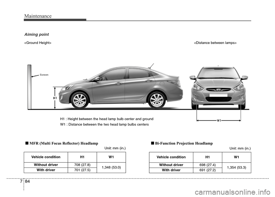
Headlight aiming
1. Inflate the tires to the specified pres-
sure and remove any loads from the
vehicle except the driver, spare tire,
and tools.2. The vehicle should be placed on a flat
floor.
3. Draw vertical lines (Vertical lines pass-
ing through respective head lamp cen-
ters) and a horizontal line (Horizontal
line passing through center of head
lamps) on the screen.
4. With the head lamp and battery in nor-
mal condition, aim the head lamps so
the brightest portion falls on the hori-
zontal and vertical lines.
5. To aim the low beam left or right, turn
the driver (1) clockwise or counter-
clockwise. To aim the low beam up or
down, turn the driver (2) clockwise or
counterclockwise.
ORB073077R
ORB073073
■MFR (Multi Focus Reflector) Headlamp
■Bi-Function Projection Headlamp
Page 375 of 402
Maintenance
84 7
Vehicle condition H1 W1
Without driver708 (27.8)
1,348 (53.0)
With driver701 (27.5)
Unit: mm (in.)
H1 : Height between the head lamp bulb center and ground
W1 : Distance between the two head lamp bulbs centers
Aiming point
Vehicle condition H1 W1
Without driver698 (27.4)
1,354 (53.3)
With driver691 (27.2)
■MFR (Multi Focus Reflector) Headlamp■Bi-Function Projection Headlamp
Unit: mm (in.)
Page 376 of 402
785
Maintenance
OMD051054L
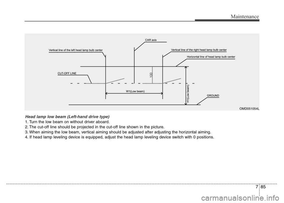
Head lamp low beam (Left-hand drive type)
1. Turn the low beam on without driver aboard.
2. The cut-off line should be projected in the cut-off line shown in the picture.
3. When aiming the low beam, vertical aiming should be adjusted after adjusting the horizontal aiming.
4. If head lamp leveling device is equipped, adjust the head lamp leveling device switch with 0 positions.
Page 377 of 402
Maintenance
86 7
OMD051055L
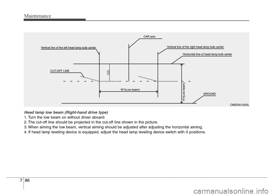
Head lamp low beam (Right-hand drive type)
1. Turn the low beam on without driver aboard.
2. The cut-off line should be projected in the cut-off line shown in the picture.
3. When aiming the low beam, vertical aiming should be adjusted after adjusting the horizontal aiming.
4. If head lamp leveling device is equipped, adjust the head lamp leveling device switch with 0 positions.
Page 378 of 402
787
Maintenance
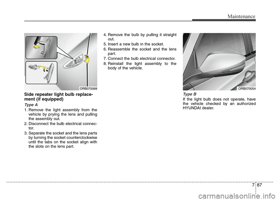
Side repeater light bulb replace-
ment (if equipped)
Type A
1. Remove the light assembly from the
vehicle by prying the lens and pulling
the assembly out.
2. Disconnect the bulb electrical connec-
tor.
3. Separate the socket and the lens parts
by turning the socket counterclockwise
until the tabs on the socket align with
the slots on the lens part.4. Remove the bulb by pulling it straight
out.
5. Insert a new bulb in the socket.
6. Reassemble the socket and the lens
part.
7. Connect the bulb electrical connector.
8. Reinstall the light assembly to the
body of the vehicle.
Type B
If the light bulb does not operate, have
the vehicle checked by an authorized
HYUNDAI dealer.
ORB070068ORB070054
Page 379 of 402
Maintenance
88 7
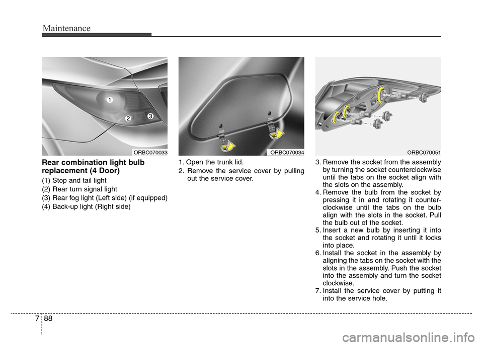
Rear combination light bulb
replacement (4 Door)
(1) Stop and tail light
(2) Rear turn signal light
(3) Rear fog light (Left side) (if equipped)
(4) Back-up light (Right side)1. Open the trunk lid.
2. Remove the service cover by pulling
out the service cover.3. Remove the socket from the assembly
by turning the socket counterclockwise
until the tabs on the socket align with
the slots on the assembly.
4. Remove the bulb from the socket by
pressing it in and rotating it counter-
clockwise until the tabs on the bulb
align with the slots in the socket. Pull
the bulb out of the socket.
5. Insert a new bulb by inserting it into
the socket and rotating it until it locks
into place.
6. Install the socket in the assembly by
aligning the tabs on the socket with the
slots in the assembly. Push the socket
into the assembly and turn the socket
clockwise.
7. Install the service cover by putting it
into the service hole.
ORBC070034ORBC070033ORBC070051
Page 380 of 402
789
Maintenance
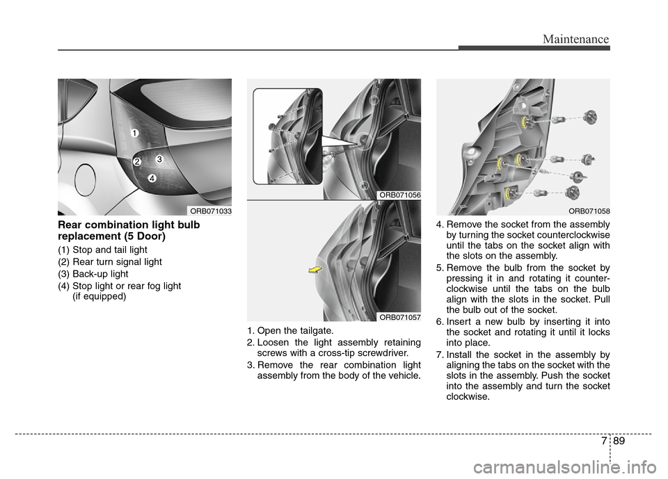
Rear combination light bulb
replacement (5 Door)
(1) Stop and tail light
(2) Rear turn signal light
(3) Back-up light
(4) Stop light or rear fog light
(if equipped)
1. Open the tailgate.
2. Loosen the light assembly retaining
screws with a cross-tip screwdriver.
3. Remove the rear combination light
assembly from the body of the vehicle.4. Remove the socket from the assembly
by turning the socket counterclockwise
until the tabs on the socket align with
the slots on the assembly.
5. Remove the bulb from the socket by
pressing it in and rotating it counter-
clockwise until the tabs on the bulb
align with the slots in the socket. Pull
the bulb out of the socket.
6. Insert a new bulb by inserting it into
the socket and rotating it until it locks
into place.
7. Install the socket in the assembly by
aligning the tabs on the socket with the
slots in the assembly. Push the socket
into the assembly and turn the socket
clockwise.
ORB071056
ORB071057
ORB071033ORB071058