instrument cluster Hyundai Accent 2013 Owner's Manual
[x] Cancel search | Manufacturer: HYUNDAI, Model Year: 2013, Model line: Accent, Model: Hyundai Accent 2013Pages: 402, PDF Size: 8.49 MB
Page 15 of 402
Your vehicle at a glance
4 2
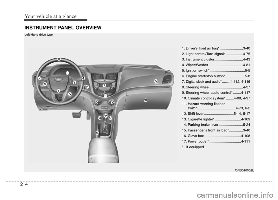
INSTRUMENT PANEL OVERVIEW
1. Driver’s front air bag* .......................3-40
2. Light control/Turn signals .................4-75
3. Instrument cluster.............................4-43
4. Wiper/Washer ...................................4-81
5. Ignition switch* ...................................5-5
6. Engine start/stop button*....................5-8
7. Digital clock and audio* .........4-112, 4-116
8. Steering wheel .................................4-37
9. Steering wheel audio control* ........4-117
10. Climate control system* ........4-88, 4-97
11. Hazard warning flasher
switch ......................................4-73, 6-2
12. Shift lever ..............................5-14, 5-17
13. Cigarette lighter* ..........................4-109
14. Parking brake lever ........................5-24
15. Passenger’s front air bag* ..............3-40
16. Glove box .....................................4-108
17. Power outlet* ................................4-111
* : if equipped
ORB010002L
Left-Hand drive type
Page 16 of 402
25
Your vehicle at a glance
ORB012002R
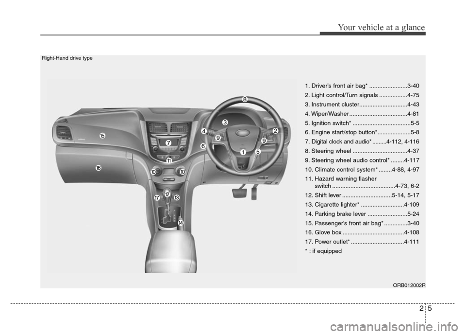
1. Driver’s front air bag* .......................3-40
2. Light control/Turn signals .................4-75
3. Instrument cluster.............................4-43
4. Wiper/Washer ...................................4-81
5. Ignition switch* ...................................5-5
6. Engine start/stop button*....................5-8
7. Digital clock and audio* .........4-112, 4-116
8. Steering wheel .................................4-37
9. Steering wheel audio control* ........4-117
10. Climate control system* ........4-88, 4-97
11. Hazard warning flasher
switch ......................................4-73, 6-2
12. Shift lever ..............................5-14, 5-17
13. Cigarette lighter* ..........................4-109
14. Parking brake lever ........................5-24
15. Passenger’s front air bag* ..............3-40
16. Glove box .....................................4-108
17. Power outlet* ................................4-111
* : if equipped
Right-Hand drive type
Page 57 of 402
339
Safety features of your vehicle
WARNING
• Do not install or place any acces-
sories (drink holder, cassette
holder, sticker, etc.) on the front
passenger's panel above the
glove box in a vehicle with a pas-
senger's air bag. Such objects
may become dangerous projec-
tiles and cause injury if the pas-
senger's air bag inflates.
• When installing a container of liq-
uid air freshener inside the vehi-
cle, do not place it near the
instrument cluster nor on the
instrument panel surface.
It may become a dangerous pro-
jectile and cause injury if the pas-
senger's air bag inflates.
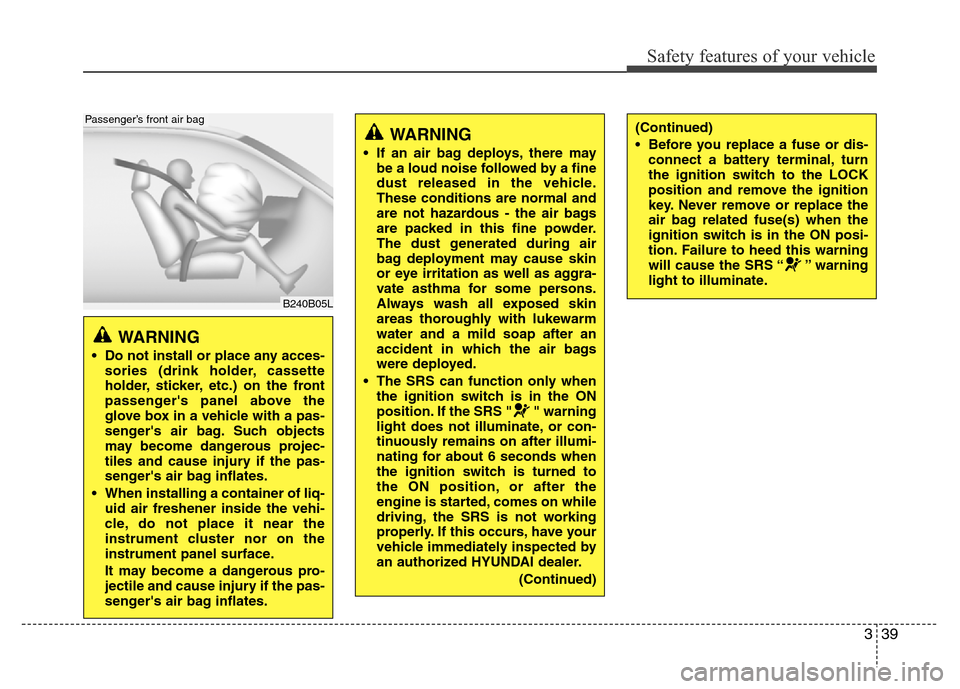
B240B05L
Passenger’s front air bag
WARNING
• If an air bag deploys, there may
be a loud noise followed by a fine
dust released in the vehicle.
These conditions are normal and
are not hazardous - the air bags
are packed in this fine powder.
The dust generated during air
bag deployment may cause skin
or eye irritation as well as aggra-
vate asthma for some persons.
Always wash all exposed skin
areas thoroughly with lukewarm
water and a mild soap after an
accident in which the air bags
were deployed.
• The SRS can function only when
the ignition switch is in the ON
position. If the SRS " " warning
light does not illuminate, or con-
tinuously remains on after illumi-
nating for about 6 seconds when
the ignition switch is turned to
the ON position, or after the
engine is started, comes on while
driving, the SRS is not working
properly. If this occurs, have your
vehicle immediately inspected by
an authorized HYUNDAI dealer.
(Continued)
(Continued)
• Before you replace a fuse or dis-
connect a battery terminal, turn
the ignition switch to the LOCK
position and remove the ignition
key. Never remove or replace the
air bag related fuse(s) when the
ignition switch is in the ON posi-
tion. Failure to heed this warning
will cause the SRS “ ” warning
light to illuminate.
Page 71 of 402
4
Keys / 4-3
Smart key / 4-6
Remote keyless entry / 4-10
Door locks / 4-13
Trunk / 4-17
Tailgate / 4-20
Windows / 4-23
Hood / 4-28
Fuel filler lid / 4-30
Sunroof / 4-33
Steering wheel / 4-37
Mirrors / 4-39
Instrument cluster / 4-43
Rear parking assist system / 4-69
Rearview camera / 4-72
Hazard warning flasher / 4-73
Lighting / 4-74
Wipers and washers / 4-81
Interior light / 4-84
Defroster / 4-87
Manual climate control system / 4-88
Automatic climate control system / 4-97
Windshield defrosting and defogging / 4-104
Features of your vehicle
Page 113 of 402
443
Features of your vehicle
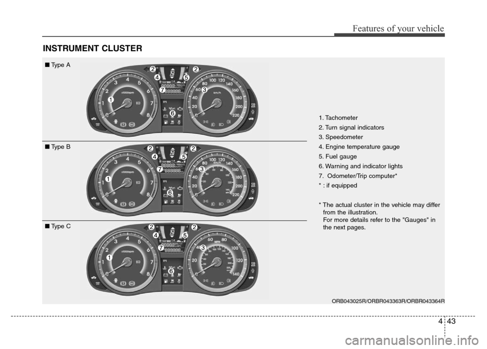
INSTRUMENT CLUSTER
1. Tachometer
2. Turn signal indicators
3. Speedometer
4. Engine temperature gauge
5. Fuel gauge
6. Warning and indicator lights
7. Odometer/Trip computer*
* : if equipped
* The actual cluster in the vehicle may differ
from the illustration.
For more details refer to the "Gauges" in
the next pages.
ORB043025R/ORBR043363R/ORBR043364R
■Type A
■Type B
■Type C
Page 122 of 402
Features of your vehicle
52 4
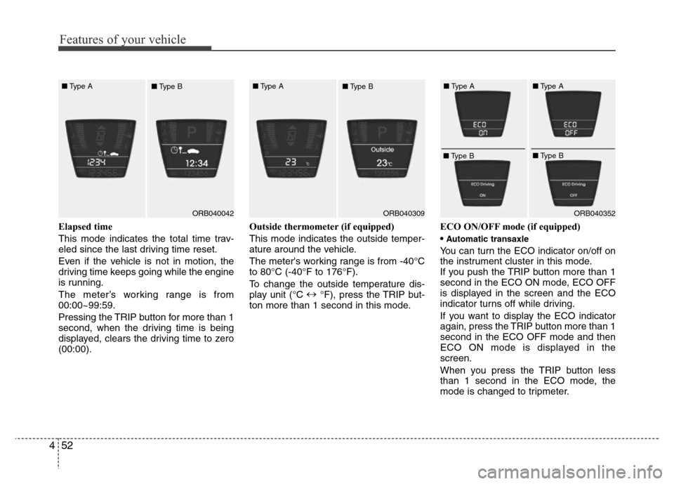
Elapsed time
This mode indicates the total time trav-
eled since the last driving time reset.
Even if the vehicle is not in motion, the
driving time keeps going while the engine
is running.
The meter’s working range is from
00:00~99:59.
Pressing the TRIP button for more than 1
second, when the driving time is being
displayed, clears the driving time to zero
(00:00).Outside thermometer (if equipped)
This mode indicates the outside temper-
ature around the vehicle.
The meter's working range is from -40°C
to 80°C (-40°F to 176°F).
To change the outside temperature dis-
play unit (°C ↔
°F), press the TRIP but-
ton more than 1 second in this mode.ECO ON/OFF mode (if equipped)
•
Automatic transaxle
You can turn the ECO indicator on/off on
the instrument cluster in this mode.
If you push the TRIP button more than 1
second in the ECO ON mode, ECO OFF
is displayed in the screen and the ECO
indicator turns off while driving.
If you want to display the ECO indicator
again, press the TRIP button more than 1
second in the ECO OFF mode and then
ECO ON mode is displayed in the
screen.
When you press the TRIP button less
than 1 second in the ECO mode, the
mode is changed to tripmeter.
ORB040042ORB040352 ■Type A
■Type BORB040309 ■Type A
■Type B■Type A
■Type B■Type A
■Type B
Page 123 of 402
453
Features of your vehicle
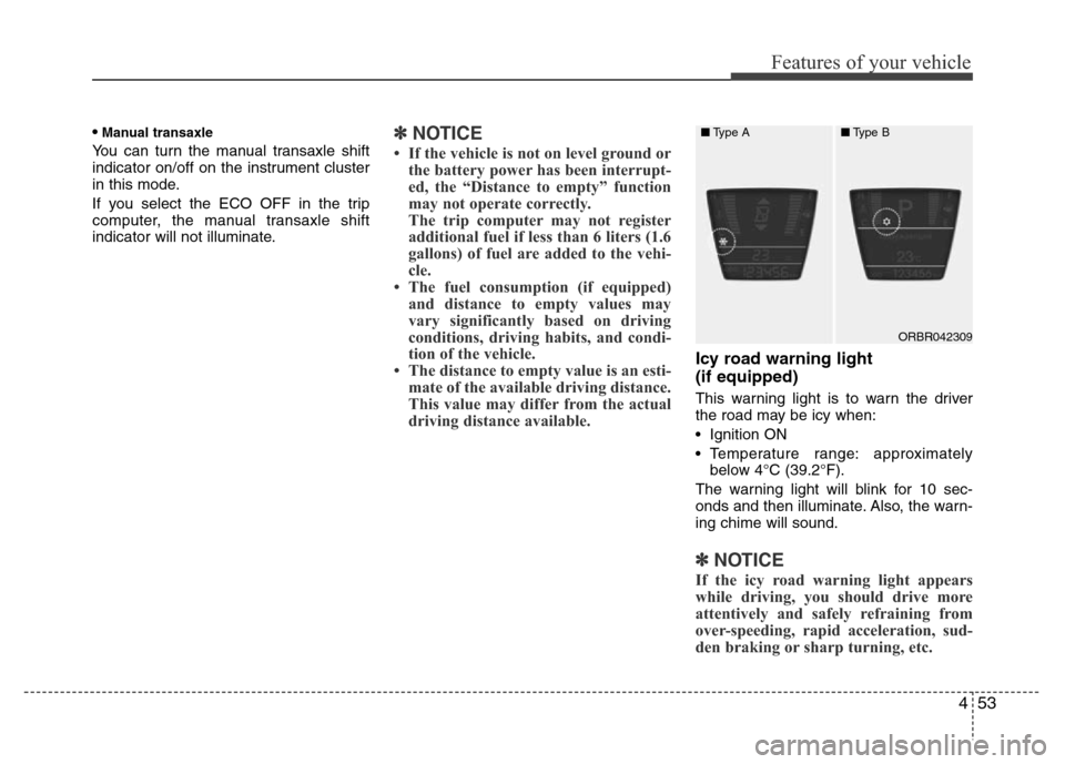
•Manual transaxle
You can turn the manual transaxle shift
indicator on/off on the instrument cluster
in this mode.
If you select the ECO OFF in the trip
computer, the manual transaxle shift
indicator will not illuminate.✽NOTICE
• If the vehicle is not on level ground or
the battery power has been interrupt-
ed, the “Distance to empty” function
may not operate correctly.
The trip computer may not register
additional fuel if less than 6 liters (1.6
gallons) of fuel are added to the vehi-
cle.
• The fuel consumption (if equipped)
and distance to empty values may
vary significantly based on driving
conditions, driving habits, and condi-
tion of the vehicle.
• The distance to empty value is an esti-
mate of the available driving distance.
This value may differ from the actual
driving distance available.
Icy road warning light
(if equipped)
This warning light is to warn the driver
the road may be icy when:
• Ignition ON
• Temperature range: approximately
below 4°C (39.2°F).
The warning light will blink for 10 sec-
onds and then illuminate. Also, the warn-
ing chime will sound.
✽NOTICE
If the icy road warning light appears
while driving, you should drive more
attentively and safely refraining from
over-speeding, rapid acceleration, sud-
den braking or sharp turning, etc.
ORBR042309 ■Type A■Type B
Page 238 of 402
Driving your vehicle
18 5
For smooth operation, depress the brake
pedal when shifting from N (Neutral) to a
forward or reverse gear.Transaxle ranges
The indicator in the instrument cluster
displays the shift lever position when the
ignition switch is in the ON position.
P (Park)
Always come to a complete stop before
shifting into P (Park). This position locks
the transaxle and prevents the drive
wheels from rotating.
WARNING- Automatic
transaxle
• Always check the surrounding
areas near your vehicle for peo-
ple, especially children, before
shifting a car into D (Drive) or R
(Reverse).
• Before leaving the driver’s seat,
always make sure the shift lever
is in the P (Park) position; then
set the parking brake fully and
shut the engine off. Unexpected
and sudden vehicle movement
can occur if these precautions
are not followed in the order iden-
tified.
CAUTION
• To avoid damage to your
transaxle, do not accelerate the
engine in R (Reverse) or any for-
ward gear position with the
brakes on.
• When stopped on an incline, do
not hold the vehicle stationary
with engine power. Use the serv-
ice brake or the parking brake.
• Do not shift from N (Neutral) or P
(Park) into D (Drive), or R
(Reverse) when the engine is
above idle speed.
WARNING
• Shifting into P (Park) while the
vehicle is in motion will cause the
drive wheels to lock which will
cause you to lose control of the
vehicle.
• Do not use the P (Park) position
in place of the parking brake.
Always make sure the shift lever
is latched in the P (Park) position
and set the parking brake fully.
• Never leave a child unattended in
a vehicle.
CAUTION
The transaxle may be damaged if
you shift into P (Park) while the
vehicle is in motion.
Page 251 of 402
531
Driving your vehicle
Vehicle stability management
(VSM) (if equipped)
This system provides further enhance-
ments to vehicle stability and steering
responses when a vehicle is driving on a
slippery road or a vehicle detected
changes in coefficient of friction between
right wheels and left wheels when brak-
ing.
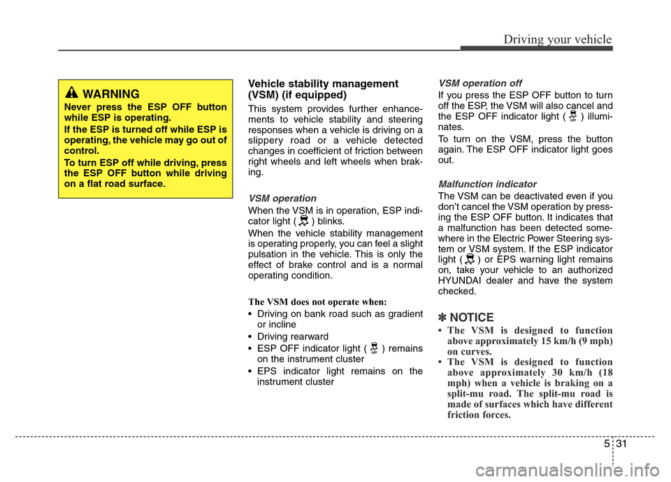
VSM operation
When the VSM is in operation, ESP indi-
cator light ( ) blinks.
When the vehicle stability management
is operating properly, you can feel a slight
pulsation in the vehicle. This is only the
effect of brake control and is a normal
operating condition.
The VSM does not operate when:
• Driving on bank road such as gradient
or incline
• Driving rearward
• ESP OFF indicator light ( ) remains
on the instrument cluster
• EPS indicator light remains on the
instrument cluster
VSM operation off
If you press the ESP OFF button to turn
off the ESP, the VSM will also cancel and
the ESP OFF indicator light ( ) illumi-
nates.
To turn on the VSM, press the button
again. The ESP OFF indicator light goes
out.
Malfunction indicator
The VSM can be deactivated even if you
don’t cancel the VSM operation by press-
ing the ESP OFF button. It indicates that
a malfunction has been detected some-
where in the Electric Power Steering sys-
tem or VSM system. If the ESP indicator
light ( ) or EPS warning light remains
on, take your vehicle to an authorized
HYUNDAI dealer and have the system
checked.
✽NOTICE
• The VSM is designed to function
above approximately 15 km/h (9 mph)
on curves.
• The VSM is designed to function
above approximately 30 km/h (18
mph) when a vehicle is braking on a
split-mu road. The split-mu road is
made of surfaces which have different
friction forces.
WARNING
Never press the ESP OFF button
while ESP is operating.
If the ESP is turned off while ESP is
operating, the vehicle may go out of
control.
To turn ESP off while driving, press
the ESP OFF button while driving
on a flat road surface.
Page 364 of 402
773
Maintenance
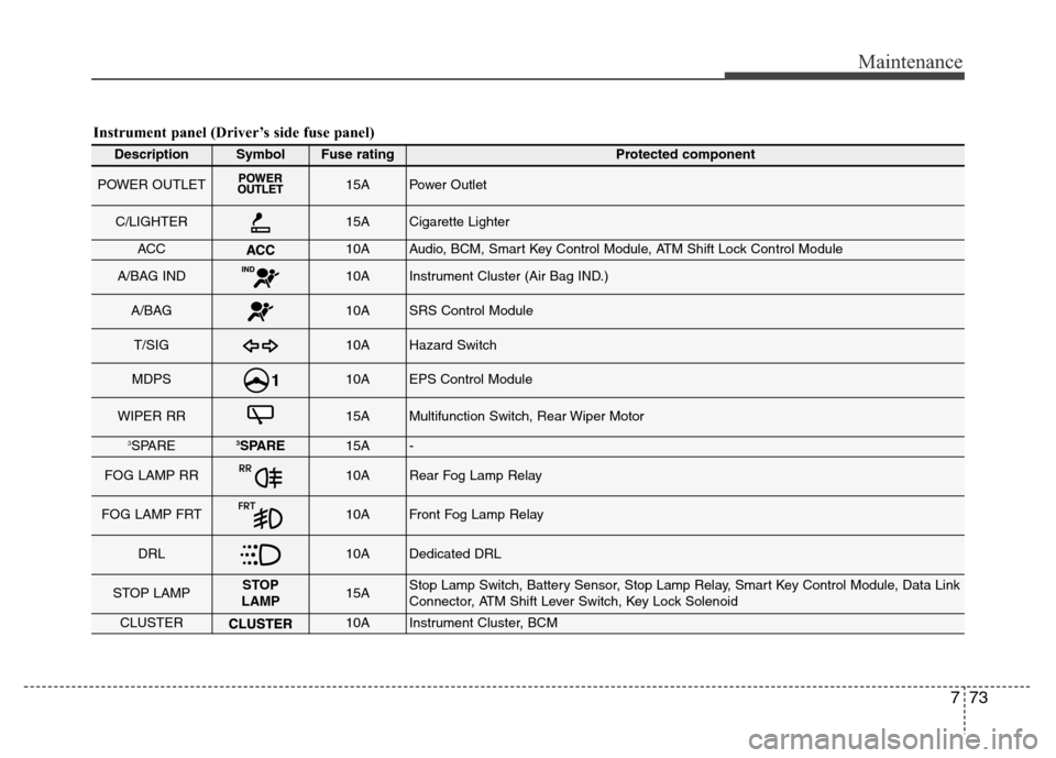
Instrument panel (Driver’s side fuse panel)
DescriptionSymbolFuse ratingProtected component
POWER OUTLET15APower Outlet
C/LIGHTER15ACigarette Lighter
ACC10AAudio, BCM, Smart Key Control Module, ATM Shift Lock Control Module
A/BAG IND10AInstrument Cluster (Air Bag IND.)
A/BAG10ASRS Control Module
T/SIG10AHazard Switch
MDPS10AEPS Control Module
WIPER RR15AMultifunction Switch, Rear Wiper Motor
3SPARE3SPARE15A-
FOG LAMP RR10ARear Fog Lamp Relay
FOG LAMP FRT10AFront Fog Lamp Relay
DRL10ADedicated DRL
STOP LAMPSTOP
LAMP15AStop Lamp Switch, Battery Sensor, Stop Lamp Relay, Smart Key Control Module, Data Link
Connector, ATM Shift Lever Switch, Key Lock Solenoid
CLUSTER10AInstrument Cluster, BCM