sensor Hyundai Accent 2018 Owner's Guide
[x] Cancel search | Manufacturer: HYUNDAI, Model Year: 2018, Model line: Accent, Model: Hyundai Accent 2018Pages: 442, PDF Size: 13.99 MB
Page 293 of 442

5-41
Driving your vehicle
5
The FCA is only a supplemen-
tal system for the driver’s con-
venience. The driver is
responsible for controlling the
vehicle operation. Do not
solely depend on the FCA
system. Rather, maintain a
safe braking distance, and, if
necessary, depress the brake
pedal to reduce the driving
speed.
In certain instances and
under certain driving condi-
tions, the FCA system may
activate prematurely. This ini-
tial warning message appears
on the LCD display with a
warning chime.
Also, in certain instances the
front radar sensor may not
detect the vehicle ahead. The
FCA system may not activate
and the warning message will
not be displayed.(Continued)
WARNING (Continued)
If there is a malfunction with
the FCA system, the forward
Collision-avoidance Assist
(FCA) is not applied even
though the braking system is
operating normally.
If the vehicle in front stops
suddenly, you may have less
control of the brake system.
Therefore, always keep a safe
distance between your vehicle
and the vehicle in front of you.
The FCA system may activate
during braking and the vehi-
cle may stop suddenly shift-
ing loose objects toward the
passengers. Always keep
loose objects secured.
The FCA system may not acti-
vate if the driver applies the
brake pedal to avoid a colli-
sion.
The brake control may be
insufficient, possibly causing
a collision, if a vehicle in front
abruptly stops. Always pay
extreme caution.(Continued)
(Continued)
Occupants may get injured, if
the vehicle abruptly stops by
the activated FCA system. Pay
extreme caution.
Page 294 of 442

5-42
Driving your vehicle
Limitations of the System
The FCA system is designed to mon-
itor the vehicle ahead on the road-
way through radar signals to warn
the driver that a collision is imminent,
and if necessary, apply emergency
braking.
In certain situations, the radar sen-
sor may not be able to detect the
vehicle ahead. In these cases, the
FCA system may not operate nor-
mally. The driver must pay careful
attention in the following situations
where the FCA operation may be
limited.
Detecting vehicles
The sensor may be limited when:
The radar sensor is blocked with aforeign object or debris
Inclement weather such as heavy rain or snow obscures the field of
view of the radar sensor
There is interference by electro- magnetic waves
There is severe irregular reflection from the radar sensor
The radar sensor recognition is limited
The vehicle in front is too small to be detected (for example a motor-
cycle or a bicycle, etc.)
The vehicle in front is an oversize vehicle or trailer that is too big to
be detected by the camera recog-
nition system (for example a tractor
trailer, etc.)
The vehicle is driven near areas containing metal substances as a
construction zone, railroad, etc.
The vehicle in front is driving errat- ically
The FCA system operates
only to detect vehicles in front
of the vehicle.
The FCA system does not
operate when the vehicle is in
reverse.
The FCA system is not
designed to detect other
objects on the road.
The FCA system does not
detect vehicles in the oppo-
site lane.
The FCA system does not
detect cross traffic vehicles
that are approaching.
The FCA system cannot
detect the driver approaching
the side view of a parked vehi-
cle (for example on a dead
end street.)
In these cases, you must main-
tain a safe braking distance,
and if necessary, depress the
brake pedal to reduce the driv-
ing speed in order to maintain a
safe distance.
WARNING
Page 295 of 442
5-43
Driving your vehicle
5
The vehicle drives through a con-struction area, on an unpaved
road, or above metal materials,
such as a railway
The vehicle drives inside a build- ing, such as a basement parking
lot
The adverse road conditions cause excessive vehicle vibrations while
driving
The vehicle in front is moving verti- cally to the driving direction
The vehicle in front is stopped ver- tically
The vehicle in front is driving towards your vehicle or reversing
The sensor recognition changes suddenly when passing over a
speed bump
The vehicle is under heavy vibra- tion
The vehicle is on roundabouts.
The radar or sensor cover is bro- ken
The vehicle is passing a tunnel, toll gate or partially paved road
The radar or camera sensor recog- nition is under other limited circum-
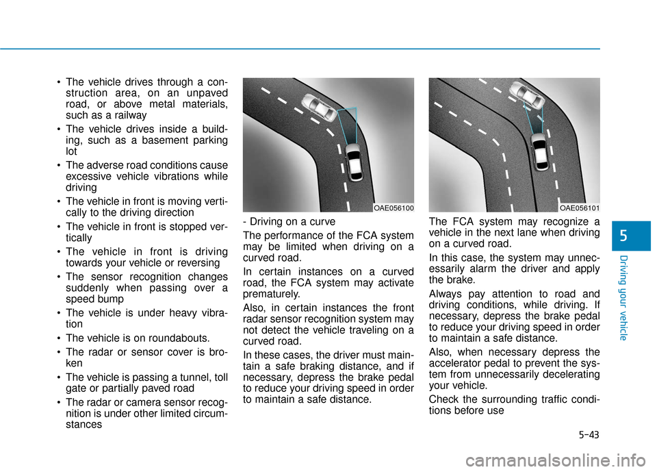
stances - Driving on a curve
The performance of the FCA system
may be limited when driving on a
curved road.
In certain instances on a curved
road, the FCA system may activate
prematurely.
Also, in certain instances the front
radar sensor recognition system may
not detect the vehicle traveling on a
curved road.
In these cases, the driver must main-
tain a safe braking distance, and if
necessary, depress the brake pedal
to reduce your driving speed in order
to maintain a safe distance.
The FCA system may recognize a
vehicle in the next lane when driving
on a curved road.
In this case, the system may unnec-
essarily alarm the driver and apply
the brake.
Always pay attention to road and
driving conditions, while driving. If
necessary, depress the brake pedal
to reduce your driving speed in order
to maintain a safe distance.
Also, when necessary depress the
accelerator pedal to prevent the sys-
tem from unnecessarily decelerating
your vehicle.
Check the surrounding traffic condi-
tions before use
OAE056100OAE056101
Page 325 of 442
6-10
What to do in an emergency
If any of the below happens, have
the system checked by an author-
ized HYUNDAI dealer.
1. The Low Tire Pressure TPMS Malfunction Indicator does not
illuminate for 3 seconds when
the ignition switch is placed to
the ON position or engine is
running.
2. The TPMS Malfunction Indicator remains illuminated after blink-
ing for approximately 1 minute.
3. The Low Tire Pressure LCD dis- play remains illuminated
Low Tire Pressure
Telltale
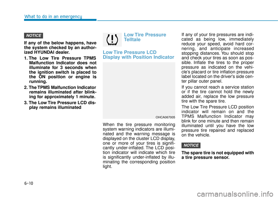
Low Tire Pressure LCD
Display with Position Indicator
When the tire pressure monitoring
system warning indicators are illumi-
nated and the warning message is
displayed on the cluster LCD display,
one or more of your tires is signifi-
cantly under-inflated. The LCD posi-
tion indicator will indicate which tire
is significantly under-inflated by illu-
minating the corresponding position
light. If any of your tire pressures are indi-
cated as being low, immediately
reduce your speed, avoid hard cor-
nering, and anticipate increased
stopping distances. You should stop
and check your tires as soon as pos-
sible. Inflate the tires to the proper
pressure as indicated on the vehi-
cle’s placard or tire inflation pressure
label located on the driver's side cen-
ter pillar outer panel.
If you cannot reach a service station
or if the tire cannot hold the newly
added air, replace the low pressure
tire with the spare tire.
The Low Tire Pressure LCD position
indicator will remain on and the
TPMS Malfunction Indicator may
blink for one minute and then remain
illuminated until you have the low
pressure tire repaired and replaced
on the vehicle.
The spare tire is not equipped with
a tire pressure sensor.
NOTICE
NOTICE
OHCA067005
Page 327 of 442
6-12
What to do in an emergency
The TPMS Malfunction Indicator
may illuminate after blinking for
one minute if the vehicle is near
electric power supply cables or
radio transmitters such as police
stations, government and public
offices, broadcasting stations,
military installations, airports,
transmitting towers, etc.
Additionally, the TPMS Malfunction
Indicator may illuminate if snow
chains are used or electronic
devices such as computers, charg-
ers, remote starters, navigation,
etc. This may interfere with normal
operation of the TPMS.
Changing a Tire with TPMS
If you have a flat tire, the Low Tire
Pressure and LCD position indicator
will come on. Have the flat tire
repaired by an authorized HYUNDAI
dealer as soon as possible or
replace the flat tire with the spare
tire.
The spare tire does not come with a
tire pressure monitoring sensor.
When the low pressure tire or the flat
tire is replaced with the spare tire,
the Low Tire Pressure LCD position
indicator will remain on. Also, the
TPMS Malfunction Indicator will illu-
minate after blinking for one minute if
the vehicle is driven at speed above
15.5 mph (25 km/h) for approximate-
ly 20 minutes. Once the original tire equipped with
a tire pressure monitoring sensor is
reinflated to the recommended pres-
sure and reinstalled on the vehicle,
the Low Tire Pressure LCD position
indicator and TPMS Malfunction
Indicator will go off within a few min-
utes of driving.
If the indicators do not disappear
after a few minutes, please visit an
authorized HYUNDAI dealer.
Each wheel is equipped with a tire
pressure sensor mounted inside the
tire behind the valve stem (except for
the spare tire). You must use TPMS
specific wheels. It is recommended
that you always have your tires serv-
iced by an authorized HYUNDAI
dealer.
NOTICE
Never use a puncture-repairing
agent not approved by HYUNDAI
dealer to repair and/or inflate a
low pressure tire. Tire sealant
not approved by HYUNDAI deal-
er may damage the tire pressure
sensor.
CAUTION
Page 337 of 442
6-22
What to do in an emergency
When towing your vehicle in an
emergency without wheel dollies:
1. Place the ignition switch in the ACC position.
2. Place the shift lever in N (Neutral).
3. Release the parking brake.
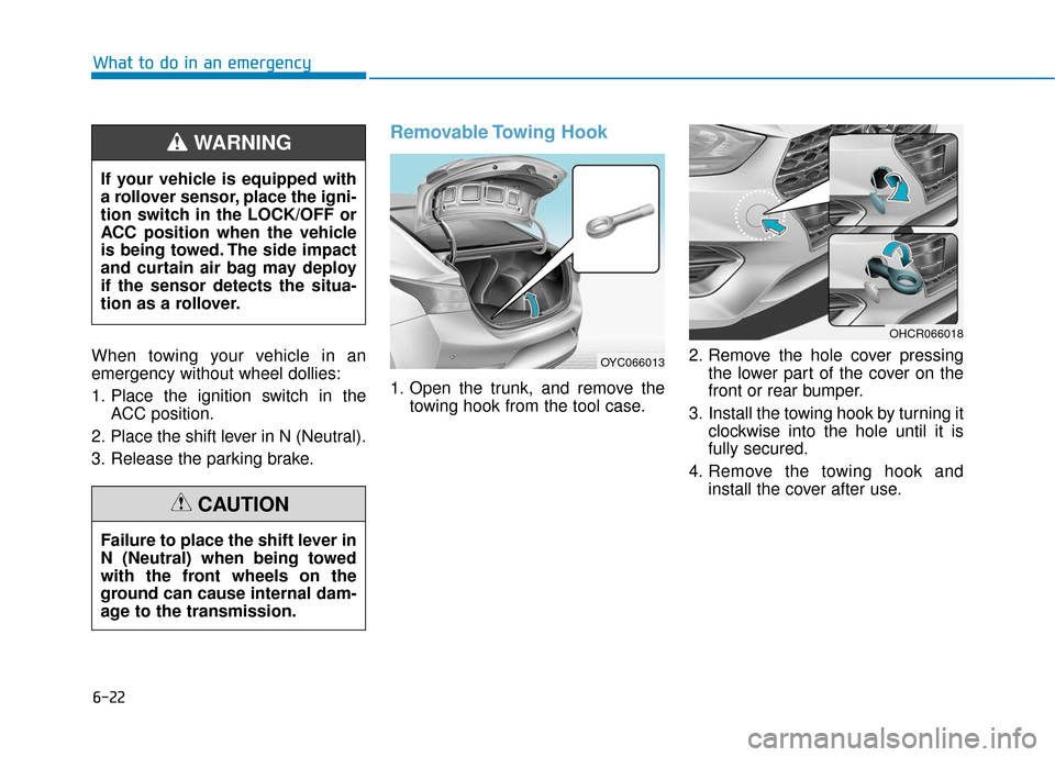
Removable Towing Hook
1. Open the trunk, and remove the towing hook from the tool case. 2. Remove the hole cover pressing
the lower part of the cover on the
front or rear bumper.
3. Install the towing hook by turning it clockwise into the hole until it is
fully secured.
4. Remove the towing hook and install the cover after use.
If your vehicle is equipped with
a rollover sensor, place the igni-
tion switch in the LOCK/OFF or
ACC position when the vehicle
is being towed. The side impact
and curtain air bag may deploy
if the sensor detects the situa-
tion as a rollover.
WARNING
Failure to place the shift lever in
N (Neutral) when being towed
with the front wheels on the
ground can cause internal dam-
age to the transmission.
CAUTION
OYC066013
OHCR066018
Page 363 of 442
7-24
Maintenance
Information
If the vehicle is operated in extremely
dusty or sandy areas, replace the ele-
ment more often than the usual rec-
ommended intervals (refer to
"Maintenance Under Severe Usage
Conditions" in this chapter).
Do not drive with the air cleanerfilter removed. This will result in
excessive engine wear.
When removing the air cleaner filter, be careful that dust or dirt
does not enter the air intake, or
damage may result.
Use HYUNDAI genuine parts. Use of non-genuine parts could
damage the air flow sensor.
Filter Inspection
The climate control air filter should
be replaced according to the
Maintenance Schedule. If the vehicle
is operated in severely air-polluted
cities or on dusty rough roads for a
long period, it should be inspected
more frequently and replaced earlier.
When you replace the climate control
air filter, replace it performing the fol-
lowing procedure, and be careful to
avoid damaging other components.
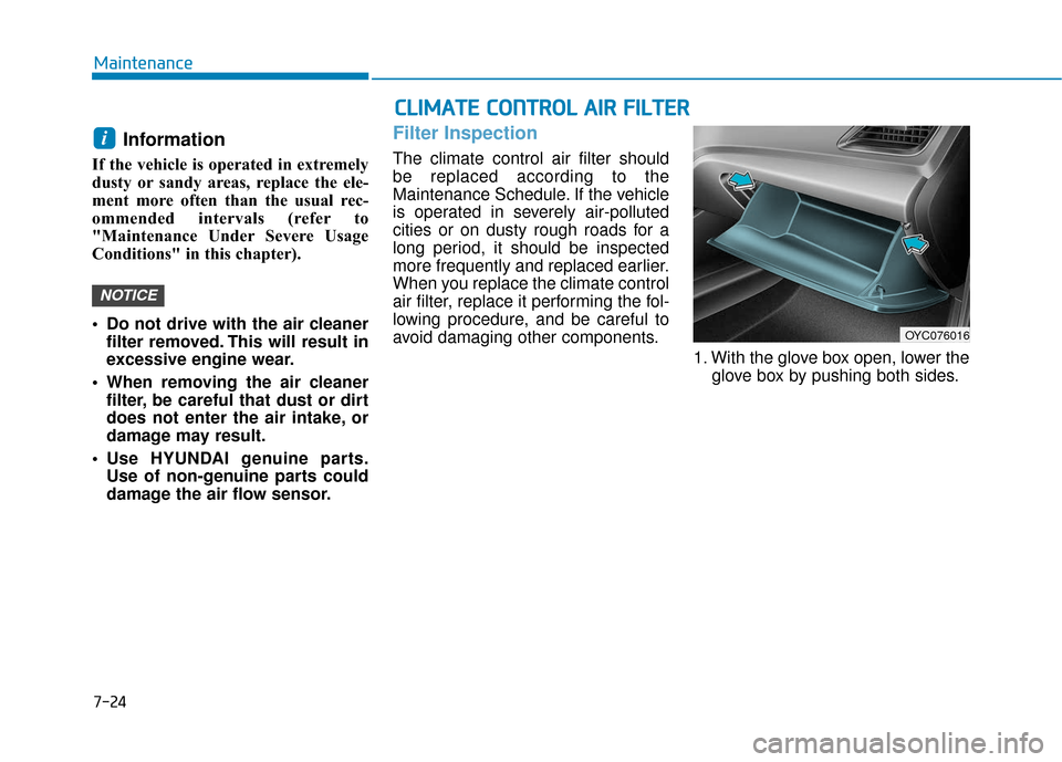
1. With the glove box open, lower theglove box by pushing both sides.
NOTICE
i
C CL
LI
IM
M A
AT
TE
E
C
C O
O N
NT
TR
R O
O L
L
A
A I
IR
R
F
F I
IL
L T
T E
ER
R
OYC076016
Page 392 of 442

7-53
7
Maintenance
Fuse NameFuse RatingCircuit Protected
FOG LAMP FRONT15AI/P Junction Block(Front Fog Lamp Relay)
A/C17.5AE/R Junction Block(Blower Relay), A/C Control Module
MODULE510ASunroof Motor, Front Seat Warmer Control Module
MODULE710ATPMS Unit
ECU10AECM/PCM, Immobilizer Module, Smart Key Control Module
SUNROOF15ASunroof Motor
IMMO.10AImmobilizer Module
MODULE610AKey Solenoid
SPARE410ASpare
MODULE47.5ASLM, BCM, Smart Key Control Module
SPARE510ASpare
AIR BAG10ASRS Control Module, Occupant Detection Sensor
Page 393 of 442

7-54
Maintenance
Fuse NameFuse RatingCircuit Protected
MODULE17.5ABCM, SLM, Key Interlock
SMART KEY25ASmart Key Control Module
A/C27.5A-
WIPER RR15AMultifunction Switch, Rear Wiper Motor, Rear Wiper Relay
WIPER FRT25AMultifunction Switch, Front Wiper Motor, E/R Junction Block(Wiper Lo Relay)
ACC10AI/P Junction Block(Power Outlet Relay), BCM, SLM, Audio,
Key Interlock Power Outside Mirror Switch, Smart Key Control Module, USB Charging Connecto
SPARE320ASpare
A/BAG IND7.5AInstrument Cluster, A/C Control Module
CLUSTER7.5AInstrument Cluster
MDPS27.5AMDPS Unit
AUDIO20AAudio
ROOM LP10AI/P Junction Block(Room Lamp Relay), Overhead Console Lamp , A/C Control Module, SLM, BCM,
Auto Light & Photo Sensor, TPMS Unit ,Instrument Cluster, Data Link Connector, Room Lamp,
Trunk Room Lamp, Electro Chromic Mirror
Page 396 of 442

7-57
7
Maintenance
Fuse NameFuse RatingCircuit Protected
MDPS80AMDPS Unit
ALT150AE/R Junction Block (Fuse - ABS1, ABS2, BLOWER, REAR HEATED)
REAR HEATED40AI/P Junction Block (Rear Defogger Relay)
ABS140AESC Module, Multipurpose Check Connector
ABS240AESC Module
BLOWER40AE/R Junction Block (Blower Relay)
WIPER10AFront Wiper Motor, Multifunction Switch, E/R Junction Block (Wiper LO Relay)
ECU415AECM/PCM
SENSOR110AOil Control Valve #1/#2, E/R Junction Block (Cooling Fan1/2 Relay),
Oxygen Sensor (Up), Oxygen Sensor (Down), Variable Intake Solenoid Valve,
Sub Relay Block (A/C Relay) Purge Control Solenoid Valve, Canister Close Valve
ECU215AECM/PCM
ECU320AECM/PCM
HEAD LAMP RH10AHead Lamp RH