headlights Hyundai Atos 2002 User Guide
[x] Cancel search | Manufacturer: HYUNDAI, Model Year: 2002, Model line: Atos, Model: Hyundai Atos 2002Pages: 249, PDF Size: 3.11 MB
Page 160 of 249
FEATURES OF YOUR HYUNDAI 1-23
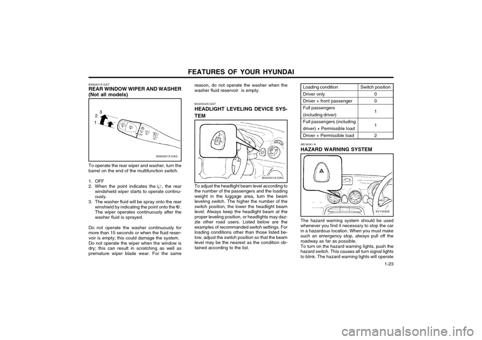
reason, do not operate the washer when the washer fluid reservoir is empty. B340G02X-GAT HEADLIGHT LEVELING DEVICE SYS- TEM To adjust the headlight beam level according to the number of the passengers and the loadingweight in the luggage area, turn the beamleveling switch. The higher the number of theswitch position, the lower the headlight beamlevel. Always keep the headlight beam at the
proper leveling position, or headlights may daz-zle other road users. Listed below are theexamples of recommanded switch settings. Forloading conditions other than those listed be-
low, adjust the switch position so that the beamlevel may be the nearest as the condition ob-tained according to the list.
B340G01A-DAG
B390A01X-GAT REAR WINDOW WIPER AND WASHER (Not all models)
B390A01X-DAG
To operate the rear wiper and washer, turn the barrel on the end of the multifunction switch.
1. OFF
2. When the point indicates the , the rear windshield wiper starts to operate continu-ously.
3. The washer fluid will be spray onto the rear winshield by indicating the point onto the .The wiper operates continuously after thewasher fluid is sprayed.
Do not operate the washer continuously formore than 15 seconds or when the fluid reser-voir is empty; this could damage the system. Do not operate the wiper when the window is dry; this can result in scratching as well aspremature wiper blade wear. For the same
1 2
3
The hazard warning system should be used
whenever you find it necessary to stop the car in a hazardous location. When you must makesuch an emergency stop, always pull off theroadway as far as possible.
To turn on the hazard warning lights, push the
hazard switch. This causes all turn signal lightsto blink. The hazard warning lights will operate AB160A1-A HAZARD WARNING SYSTEM
XV10590E
Loading condition Driver only Driver + front passenger Full passengers(including driver)Full passengers (including driver) + Permissible load Driver + Permissible load
Switch position
0 0 1 1 2
Page 163 of 249
FEATURES OF YOUR HYUNDAI
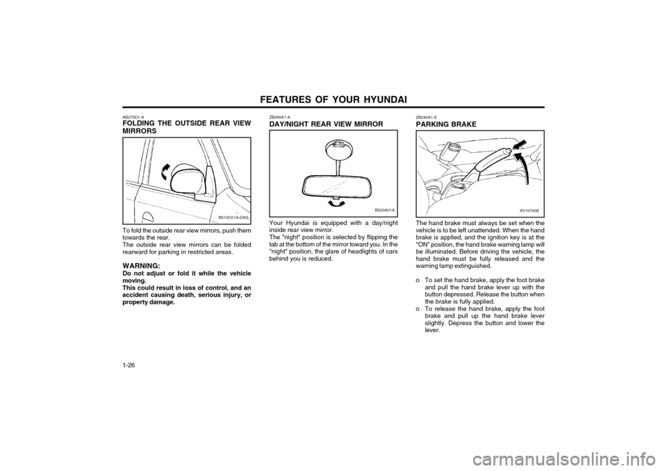
1-26 ZB290A1-E PARKING BRAKE
XV10740E
The hand brake must always be set when the vehicle is to be left unattended. When the handbrake is applied, and the ignition key is at the"ON" position, the hand brake warning lamp willbe illuminated. Before driving the vehicle, thehand brake must be fully released and thewarning lamp extinguished.
o To set the hand brake, apply the foot brake and pull the hand brake lever up with thebutton depressed. Release the button whenthe brake is fully applied.
o To release the hand brake, apply the foot brake and pull up the hand brake leverslightly. Depress the button and lower thelever.
ZB280A1-A DAY/NIGHT REAR VIEW MIRROR
B520A01A
Your Hyundai is equipped with a day/night inside rear view mirror. The "night" position is selected by flipping the tab at the bottom of the mirror toward you. In the"night" position, the glare of headlights of carsbehind you is reduced.
AB270D1-A FOLDING THE OUTSIDE REAR VIEW
MIRRORS
To fold the outside rear view mirrors, push them
towards the rear.
The outside rear view mirrors can be folded
rearward for parking in restricted areas.
WARNING: Do not adjust or fold it while the vehicle
moving.
This could result in loss of control, and an
accident causing death, serious injury, or property damage.B510C01A-DAG
Page 166 of 249
FEATURES OF YOUR HYUNDAI 1-29
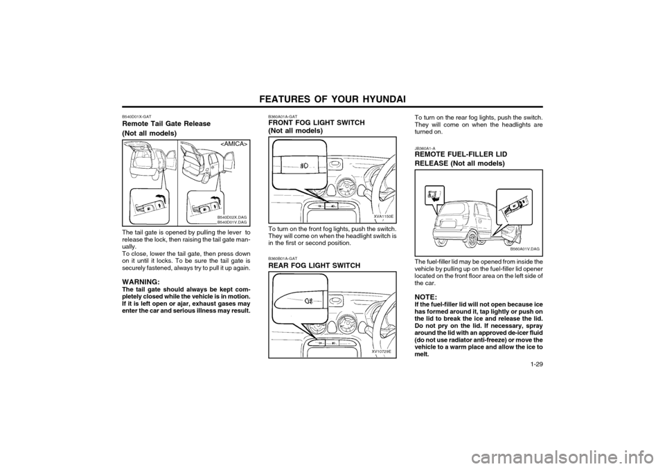
To turn on the rear fog lights, push the switch.
They will come on when the headlights areturned on. JB360A1-A REMOTE FUEL-FILLER LID RELEASE (Not all models) The fuel-filler lid may be opened from inside the
vehicle by pulling up on the fuel-filler lid opener located on the front floor area on the left side ofthe car.
NOTE:If the fuel-filler lid will not open because ice
has formed around it, tap lightly or push onthe lid to break the ice and release the lid.Do not pry on the lid. If necessary, sprayaround the lid with an approved de-icer fluid(do not use radiator anti-freeze) or move thevehicle to a warm place and allow the ice tomelt.
B560A01V.DAG
To turn on the front fog lights, push the switch. They will come on when the headlight switch is in the first or second position.
XV10729E
B360B01A-GAT REAR FOG LIGHT SWITCH
B540D01X-GATRemote Tail Gate Release (Not all models)
The tail gate is opened by pulling the lever to release the lock, then raising the tail gate man-ually.To close, lower the tail gate, then press down
on it until it locks. To be sure the tail gate issecurely fastened, always try to pull it up again. WARNING: The tail gate should always be kept com-
pletely closed while the vehicle is in motion.If it is left open or ajar, exhaust gases may
enter the car and serious illness may result. B360A01A-GAT FRONT FOG LIGHT SWITCH (Not all models)
XVA1150E
B540D02X.DAG B540D01V.DAG
Page 235 of 249
DO-IT-YOURSELF MAINTENANCE 6-17
WARNING: The halogen bulb contains gas under pres-
sure and if impacted could shatter, and re- sulting in flying fragments. Always wear eye
protection when servicing the bulb. Protectthe bulb against abrasions or scratches andagainst liquids when lighted. Turn on thebulb only when installing in a headlight.Replace the headlight if damaged or cracked.Keep the bulb out of the reach of childrenand dispose of the used bulb with care.
G290A01X-EAT
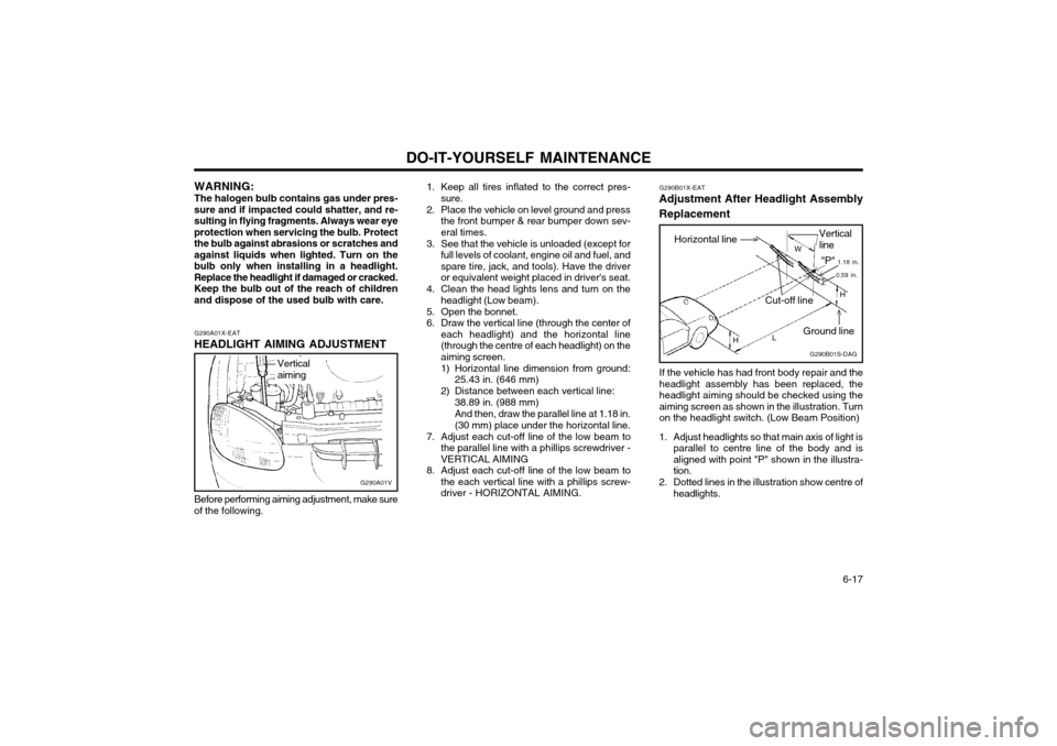
HEADLIGHT AIMING ADJUSTMENT
G290A01V
Before performing aiming adjustment, make sure
of the following.
Vertical aiming
1. Keep all tires inflated to the correct pres- sure.
2. Place the vehicle on level ground and press the front bumper & rear bumper down sev- eral times.
3. See that the vehicle is unloaded (except for full levels of coolant, engine oil and fuel, andspare tire, jack, and tools). Have the driveror equivalent weight placed in driver's seat.
4. Clean the head lights lens and turn on the headlight (Low beam).
5. Open the bonnet.
6. Draw the vertical line (through the center of each headlight) and the horizontal line(through the centre of each headlight) on theaiming screen.
1) Horizontal line dimension from ground:25.43 in. (646 mm)
2) Distance between each vertical line: 38.89 in. (988 mm)And then, draw the parallel line at 1.18 in. (30 mm) place under the horizontal line.
7. Adjust each cut-off line of the low beam to the parallel line with a phillips screwdriver -VERTICAL AIMING
8. Adjust each cut-off line of the low beam to the each vertical line with a phillips screw-driver - HORIZONTAL AIMING. G290B01X-EAT
Adjustment After Headlight Assembly Replacement
If the vehicle has had front body repair and the headlight assembly has been replaced, theheadlight aiming should be checked using theaiming screen as shown in the illustration. Turnon the headlight switch. (Low Beam Position)
1. Adjust headlights so that main axis of light is parallel to centre line of the body and isaligned with point "P" shown in the illustra-tion.
2. Dotted lines in the illustration show centre of headlights. G290B01S-DAG
Horizontal lineVertical line
W
0.59 in.
"P" 1.18 in.
Cut-off line
Ground line H
H L
Page 236 of 249
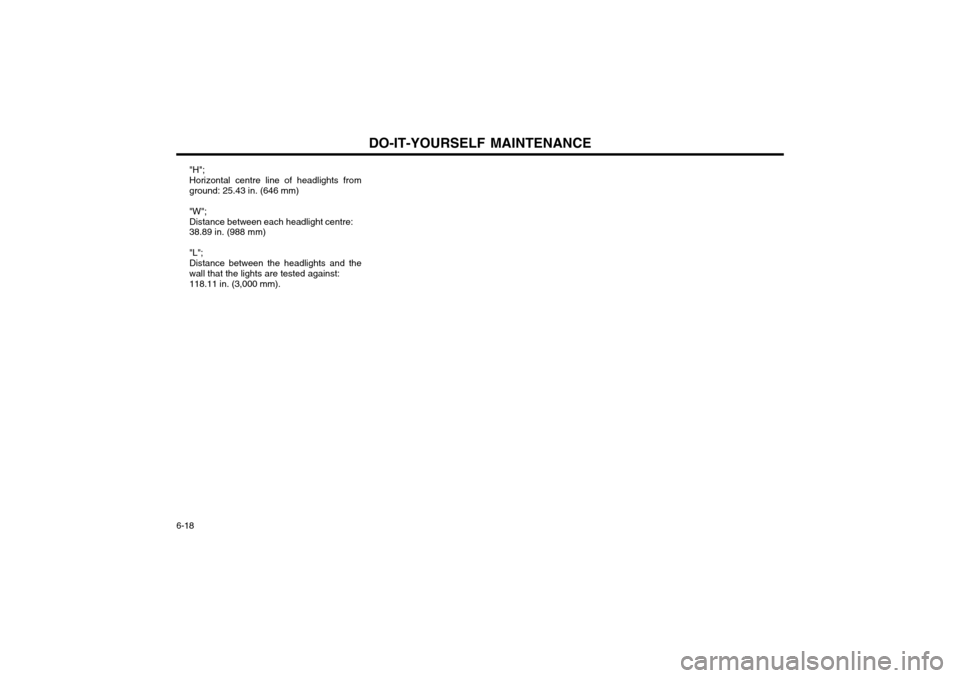
DO-IT-YOURSELF MAINTENANCE
6-18 "H"; Horizontal centre line of headlights from ground: 25.43 in. (646 mm) "W"; Distance between each headlight centre: 38.89 in. (988 mm) "L"; Distance between the headlights and the wall that the lights are tested against: 118.11 in. (3,000 mm).