fuel Hyundai Azera 2010 Owner's Guide
[x] Cancel search | Manufacturer: HYUNDAI, Model Year: 2010, Model line: Azera, Model: Hyundai Azera 2010Pages: 334, PDF Size: 12.24 MB
Page 222 of 334
2
DRIVING YOUR HYUNDAI
19
!
!
WARNING:
USE OF LIGHTSC180A01A-AATCheck your lights regularly for correct op-
eration and always keep them clean. When
driving during the day in conditions of poor
visibility, it is helpful to drive with head-
lights on low beam. This enables you to be
seen, as well as to see.
HIGHER SPEED MOTORINGC170A02A-AATPre-Trip Inspections1. Tires:
Adjust the tire inflation pressures to speci-
fication. Low tire inflation pressures will
result in overheating and possible failure
of the tires.
Avoid using worn or damaged tires which
may result in reduced traction or tire fail-
ure.NOTE:Never exceed the maximum tire infla-
tion pressure shown on the tires.
WARNING:
o Underinflated or overinflated tires can
cause poor handling, loss of vehicle
control, and sudden tire failure lead-
ing to accidents, injuries, and even
death. Always check tires are prop-
erly inflated before driving. Refer to
pages 2-23 and 8-3 for proper tire
pressures and further information.o Driving on tires with no or insufficient
tread is dangerous. Worn-out tires
can result in loss of vehicle control,
collisions, injury, and even death.
Worn-out tires should be replaced as
soon as possible and should never be
used for driving. Always check tire
tread before driving your car. Refer to
8-11 for further information and tread
limits.
2. Fuel, engine coolant and engine oil:
High speed travel consumes more fuel
than urban motoring. Do not forget to check
both engine coolant and engine oil.
3. Drive belt:
A loose or damaged drive belt may result
in overheating of the engine.
Page 225 of 334
2
DRIVING YOUR HYUNDAI
22
!
lbs(kg)
!
Tongue
200 (90)
- With Brake
Without BrakeMaximum Towable Weight
Trailer
2000 (900)
1000 (450)
CAUTION:
The following specifications are recom-
mended when towing a trailer. The loaded
trailer weight cannot safely exceed the
values in the chart below.
WARNING:
o Improperly loading your vehicle and
trailer can seriously affect its steer-
ing and braking performance causing
a crash which could cause serious
injury or death.
o Towing a trailer affects vehicle han-
dling and braking.
o Drive more slowly when towing a trailer
and allow more distance when brak-
ing.
o Be careful when driving in slippery
and windy conditions.
o Be careful when turning and while
driving up and down hills. 3. The front or rear axle weight must not
exceed the Gross Axle Weight Rating
(GAWR) shown on the vehicle identi-
fication plate (see page 8-2). It is pos-
sible that your towing package does
not exceed the GVWR but exceeds
the GAWR. Improper trailer loading
and/or too much luggage in the trunk
can overload the rear axle. Redistrib-
ute the load and check the axle weight
again.
C190F01TG-AATTrailer or Vehicle Towing Tips1. Before towing, check hitch and safety
chain connections as well as proper
operation of the trailer running lights,
brake lights, and turn signals.
2. Always drive your vehicle at a moder-
ate speed. (Less than 60 mph)
3. Trailer towing requires more fuel than
normal conditions.
4. To maintain engine braking efficiency
and electrical charging performance,
do not tow a trailer with the transaxle
engaged in overdrive gear.
5. Always secure items in the trailer to
prevent load shift while driving.
6. Check the condition and air pressure
of all tires on the trailer and your car.
Low tire pressure can seriously affect
the handling. Also check the spare tire.
7. The vehicle/trailer combination is more
affected by crosswind and buffeting.
When being passed by a large vehicle,
keep a constant speed and steer
straight ahead. If there is too much
wind buffeting, slow down to get out of
the other vehicle's air turbulence.
Page 230 of 334
2
DRIVING YOUR HYUNDAI
27
!
WARNING:
o Do not load your vehicle any
heavier than the GVWR, either the
maximum front or rear GAWR and
vehicle capacity weight. If you do,
parts, including tires on your ve-
hicle can break, and it can change
the way your vehicle handles and
braking ability. This could cause
you to lose control and crash.
Also, overloading can shorten the
life of your vehicle.
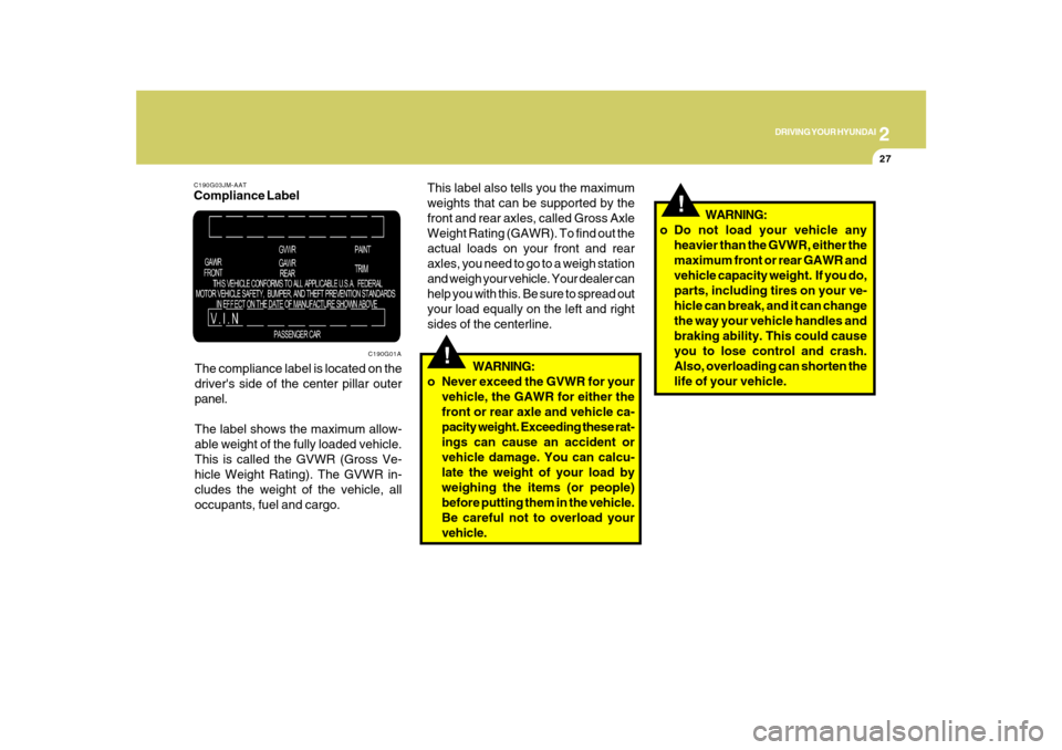
C190G03JM-AATCompliance Label
The compliance label is located on the
driver's side of the center pillar outer
panel.
The label shows the maximum allow-
able weight of the fully loaded vehicle.
This is called the GVWR (Gross Ve-
hicle Weight Rating). The GVWR in-
cludes the weight of the vehicle, all
occupants, fuel and cargo.
C190G01A
!
This label also tells you the maximum
weights that can be supported by the
front and rear axles, called Gross Axle
Weight Rating (GAWR). To find out the
actual loads on your front and rear
axles, you need to go to a weigh station
and weigh your vehicle. Your dealer can
help you with this. Be sure to spread out
your load equally on the left and right
sides of the centerline.
WARNING:
o Never exceed the GVWR for your
vehicle, the GAWR for either the
front or rear axle and vehicle ca-
pacity weight. Exceeding these rat-
ings can cause an accident or
vehicle damage. You can calcu-
late the weight of your load by
weighing the items (or people)
before putting them in the vehicle.
Be careful not to overload your
vehicle.
Page 233 of 334
32WHAT TO DO IN AN EMERGENCY
IF THE ENGINE WILL NOT
START!
D010A01A-AAT
D010B01TG-AATIf Engine Doesn't Turn Over or Turns
Over Slowly
D010C02Y-AATIf Engine Turns Over Normally but
Does Not Start1. Check fuel level.
2. With the key in the "OFF" position, check
all connectors at ignition, coil and spark
plugs. Reconnect any that may be dis-
connected or loose.
3. Check the fuel line in the engine com-
partment.
4. If the engine still does not start, call a
Hyundai dealer or seek other qualified
assistance.
D010D01A-AATIf Engine Stalls While Driving1. Reduce your speed gradually, keeping
a straight line. Move cautiously off the
road to a safe place.
2. Turn on your emergency flashers.
3. Try to start the engine again. If your
vehicle will not start, contact a Hyundai
dealer or seek other qualified assis-
tance.
WARNING:
If the engine will not start, do not push or
pull the car to start it. This could result in
a collision or cause other damage. In
addition, push or pull starting may cause
the catalytic converter to be overloaded
and create a fire hazard.
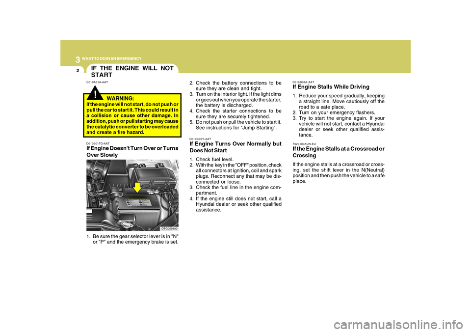
1. Be sure the gear selector lever is in "N"
or "P" and the emergency brake is set.
OTG059400
2. Check the battery connections to be
sure they are clean and tight.
3. Turn on the interior light. If the light dims
or goes out when you operate the starter,
the battery is discharged.
4. Check the starter connections to be
sure they are securely tightened.
5. Do not push or pull the vehicle to start it.
See instructions for "Jump Starting".
F020100AUN-EUIf the Engine Stalls at a Crossroad or
CrossingIf the engine stalls at a crossroad or cross-
ing, set the shift lever in the N(Neutral)
position and then push the vehicle to a safe
place.
Page 236 of 334
3
WHAT TO DO IN AN EMERGENCY
5
TIRE PRESSURE MONITORING SYSTEM (TPMS)
C320A01TG C320A01TG-AAT
(If Installed)
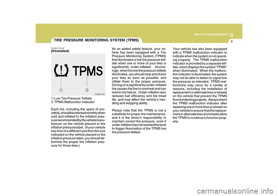
➀ Low Tire Pressure Telltale
➁ TPMS Malfunction Indicator
Each tire, including the spare (if pro-
vided), should be checked monthly when
cold and inflated to the inflation pres-
sure recommended by the vehicle manu-
facturer on the vehicle placard or tire
inflation pressure label. (If your vehicle
has tires of a different size than the size
indicated on the vehicle placard or tire
inflation pressure label, you should de-
termine the proper tire inflation pres-
sure for those tires.)As an added safety feature, your ve-
hicle has been equipped with a Tire
Pressure Monitoring System (TPMS)
that illuminates a low tire pressure tell-
tale when one or more of your tires is
significantly under-inflated. Accord-
ingly, when the low tire pressure telltale
illuminates, you should stop and check
your tires as soon as possible, and
inflate them to the proper pressure.
Driving on a significantly under-inflated
tire causes the tire to overheat and can
lead to tire failure. Under-inflation also
reduces fuel efficiency and tire tread
life, and may affect the vehicle’s han-
dling and stopping ability.
Please note that the TPMS is not a
substitute for proper tire maintenance,
and it is the driver’s responsibility to
maintain correct tire pressure, even if
under-inflation has not reached the level
to trigger illumination of the TPMS low
tire pressure telltale.Your vehicle has also been equipped
with a TPMS malfunction indicator to
indicate when the system is not operat-
ing properly. The TPMS malfunction
indicator is provided by a separate tell-
tale, which displays the symbol "TPMS"
when illuminated. When the malfunc-
tion indicator is illuminated, the system
may not be able to detect or signal low
tire pressure as intended. TPMS mal-
functions may occur for a variety of
reasons, including the installation of
replacement or alternate tires or wheels
on the vehicle that prevent the TPMS
from functioning properly. Always check
the TPMS malfunction indicator after
replacing one or more tires or wheels on
your vehicle to ensure that the replace-
ment or alternate tires and wheels allow
the TPMS to continue to function prop-
erly.
Page 259 of 334
5
VEHICLE MAINTENANCE REQUIREMENTS
3
SCHEDULED MAINTE-
NANCE REQUIREMENTSF020A02Y-AATo Inspection should be performed any
time a malfunction is experienced or
suspected.
o Receipts for all emission control system
services should be retained to demon-
strate compliance with conditions of the
emissions system warranty.
o After 120 months or 150,000 miles
(240,000 km), continue to follow the
prescribed maintenance intervals.
o For severe usage maintenance require-
ments, see page 5-6 of this section.
F010D02A-AATGeneral ChecksThese are the regular checks you should
perform when you drive your Hyundai or
you fill the fuel tank. A list of these items will
be found on page 6-3.F010E01A-AATDo-It-Yourself MaintenanceIf you are mechanically inclined, own a few
tools that are required and want to take the
time to do so, you can inspect and service
a number of items. For more information
about doing it yourself, see Section 6.
F010F01A-AATA Few Tipso Whenever you have your Hyundai ser-
viced, keep copies of the service records
in your glove box. This will help ensure
that you can document that the required
procedures have been performed to
keep your warranties in effect. This is
especially important when service is
not performed by an authorized
Hyundai dealer.
o If you choose to do your own mainte-
nance and repairs, you may find it
helpful to have an official Hyundai Shop
Manual. A copy of this publication may
be purchased at your Hyundai dealer's
parts department.
Page 260 of 334
5
VEHICLE MAINTENANCE REQUIREMENTS4
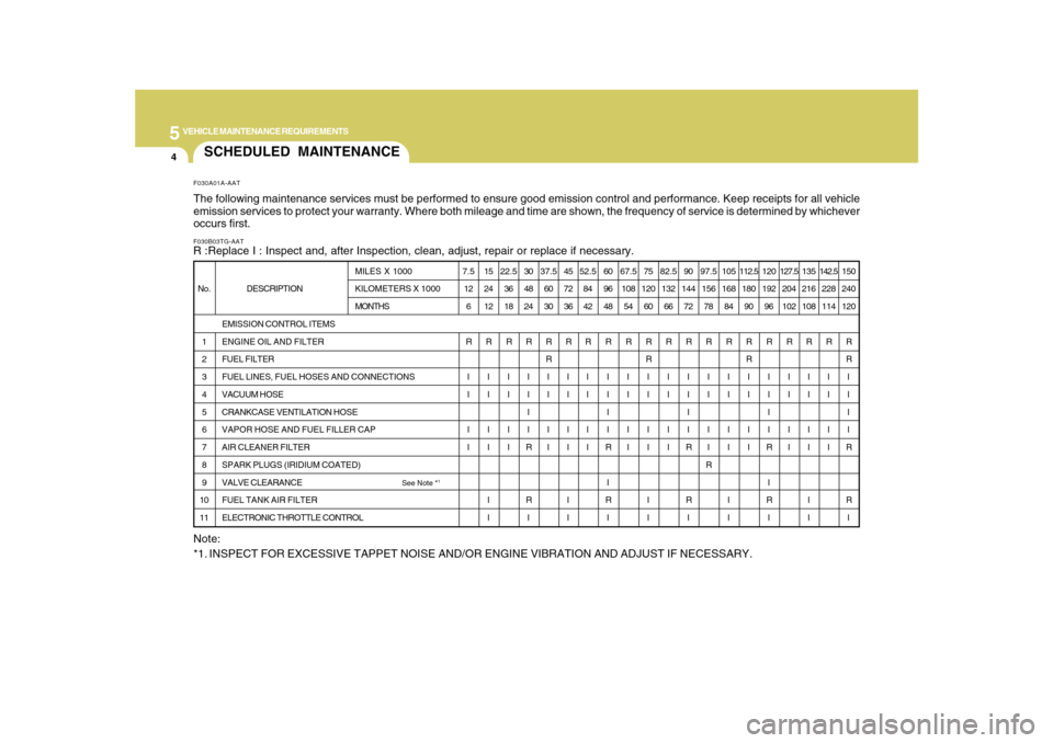
SCHEDULED MAINTENANCEF030B03TG-AATR :Replace I : Inspect and, after Inspection, clean, adjust, repair or replace if necessary.F030A01A-AATThe following maintenance services must be performed to ensure good emission control and performance. Keep receipts for all vehicle
emission services to protect your warranty. Where both mileage and time are shown, the frequency of service is determined by whichever
occurs first.
DESCRIPTION
EMISSION CONTROL ITEMS
ENGINE OIL AND FILTER
FUEL FILTER
FUEL LINES, FUEL HOSES AND CONNECTIONS
VACUUM HOSE
CRANKCASE VENTILATION HOSE
VAPOR HOSE AND FUEL FILLER CAP
AIR CLEANER FILTER
SPARK PLUGS (IRIDIUM COATED)
VALVE CLEARANCE
See Note *
1
FUEL TANK AIR FILTER
ELECTRONIC THROTTLE CONTROL No.
1
2
3
4
5
6
7
8
9
10
11MILES X 1000
KILOMETERS X 1000
MONTHS7.5
12
6
R
I
I
I
I15
24
12
R
I
I
I
I
I
I22.5
36
18
R
I
I
I
I30
48
24
R
I
I
I
I
R
R
I37.5
60
30
R
R
I
I
I
I45
72
36
R
I
I
I
I
I
I52.5
84
42
R
I
I
I
I60
96
48
R
I
I
I
I
R
I
R
I67.5
108
54
R
I
I
I
I75
120
60
R
R
I
I
I
I
I
I82.5
132
66
R
I
I
I
I90
144
72
R
I
I
I
I
R
R
I97.5
156
78
R
I
I
I
I
R105
168
84
R
I
I
I
I
I
I112.5
180
90
R
R
I
I
I
I120
192
96
R
I
I
I
I
R
I
R
I127.5
204
102
R
I
I
I
I135
216
108
R
I
I
I
I
I
I142.5
228
114
R
I
I
I
I150
240
120
R
R
I
I
I
I
R
R
I
Note:
*1. INSPECT FOR EXCESSIVE TAPPET NOISE AND/OR ENGINE VIBRATION AND ADJUST IF NECESSARY.
Page 263 of 334
5
VEHICLE MAINTENANCE REQUIREMENTS
7
F060D01A-AATo Fuel Lines, Fuel Hoses and Con-
nectionsCheck the fuel lines, fuel hoses and con-
nections for leakage and damage. Have a
trained technician replace any damaged
or leaking parts immediately.F060B01NF-GATo Drive BeltsInspect all drive belts for evidence of cuts,
cracks, excessive wear or oil saturation
and replace if necessary. Drive belts should
be checked periodically for proper ten-
sion.
F060M01A-AATo Engine Oil and FilterThe engine oil and filter should be changed
at the intervals specified in the mainte-
nance schedule. If the car is being driven
in severe conditions, more frequent oil and
filter changes are required.F060C01A-AATo Fuel FilterA clogged filter can limit the speed at which
the vehicle may be driven, damage the
emission system and cause hard starting.
If an excessive amount of foreign matter
accumulates in the fuel tank, the filter may
require replacement more frequently.
After installing a new filter, run the engine
for several minutes, and check for leaks at
the connections. Fuel filters should be
installed by trained technicians.
F060F01A-AATo Vacuum, Crankcase Ventilation
HosesInspect the surface of hoses for evidence
of heat and/or mechanical damage. Hard
and brittle rubber, cracking, tears, cuts,
abrasions, and excessive swelling indi-
cate deterioration. Particular attention
should be paid to examine those hose
surfaces nearest to high heat sources,
such as the exhaust manifold.
Inspect the hose routing to assure that the
hoses do not come in contact with any heat
source, sharp edges or moving compo-
nent which might cause heat damage or
mechanical wear. Inspect all hose con-
nections, such as clamps and couplings,
to make sure they are secure, and that no
leaks are present. Hoses should be re-
placed immediately if there is any evi-
dence of deterioration or damage.
EXPLANATION OF SCHEDULED MAINTENANCE ITEMS
Page 264 of 334
5
VEHICLE MAINTENANCE REQUIREMENTS8
F070G02A-AATo Brake FluidCheck brake fluid level in the brake fluid
reservoir. The level should be between
"MIN" and "MAX" marks on the side of the
reservoir. Use only hydraulic brake fluid
conforming to DOT 3 or DOT 4.F070F01A-AATo Brake Hoses and LinesVisually check for proper installation, chaf-
ing, cracks, deterioration and any leak-
age. Replace any deteriorated or dam-
aged parts immediately.
F070E06A-AATo Automatic Transaxle FluidThe fluid level should be in the “HOT”
range of the dipstick, after the engine and
transaxle are at normal operating tem-
perature. Check the automatic transaxle
fluid level with the engine running and the
transaxle in neutral, with the parking brake
properly applied. Use HYUNDAI GENU-
INE ATF SP III, DIAMOND ATF SP III, SK
ATF SP III or other brands meeting the SP
III specification approved by Hyundai Motor
Co. when adding or changing fluid. Using
the wrong ATF may result in damage to the
ATM.F070C01A-AATo CoolantThe coolant should be changed at the
intervals specified in the maintenance
schedule.
F060J01A-AATo Spark PlugsMake sure to install new spark plugs of the
correct heat range.F060H01A-AATo Air Cleaner FilterA Genuine Hyundai air cleaner filter is
recommended when the filter is replaced.F060G01A-AATo Vapor Hose and Fuel Filler CapThe vapor hose and fuel filler cap should
be inspected at those intervals specified in
the maintenance schedule. Make sure that
a new vapor hose or fuel filler cap is cor-
rectly replaced.F060N02E-AATo Valve ClearanceInspect excessive valve noise and/or en-
gine vibration and adjust if necessary. A
qualified technician should perform the
operation.
F070H01TG-AATo Rear Disc Brake /
Linings, Parking BrakeCheck the rear disc brake and linings for
scoring, burning, leaking fluid, broken parts,
and excessive wear. Inspect the parking
brake system including the parking brake
pedal and cables. For detailed service
procedures, refer to the Shop Manual.
Page 300 of 334
6
DO-IT-YOURSELF MAINTENANCE
34
1
2
3
4
5
6
7
8
9
10
11
12
13
14
15
16
17
18
19
20
21
22
23
24
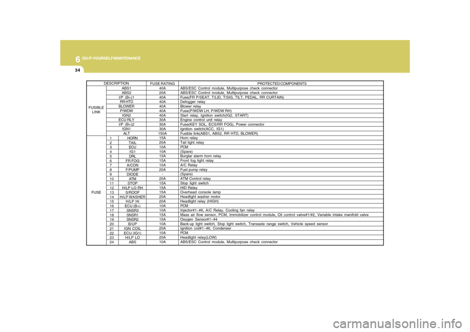
HORN
TAIL
ECU
IG1
DRL
FR FOG
A/CON
F/PUMP
DIODE
ATM
STOP
H/LP LO RH
S/ROOF
H/LP WASHER
H/LP HI
ECU (B+)
SNSR3
SNSR1
SNSR2
B/UP
IGN COIL
ECU (IG1)
H/LP LO
ABSPROTECTED COMPONENTS
ABS/ESC Control module, Multipurpose check connector
ABS/ESC Control module, Multipurpose check connector
Fuse(FR P/SEAT, T/LID, T/SIG, TILT, PEDAL, RR CURTAIN)
Defogger relay
Blower relay
Fuse(P/WDW LH, P/WDW RH)
Start relay, Ignition switch(IG2, START)
Engine control unit relay
Fuse(KEY SOL, ECS/RR FOG), Power connector
Ignition switch(ACC, IG1)
Fusible link(ABS1, ABS2, RR HTD, BLOWER)
Horn relay
Tail light relay
PCM
(Spare)
Burglar alarm horn relay
Front fog light relay
A/C Relay
Fuel pump relay
(Spare)
ATM Control relay
Stop light switch
HID Relay
Overhead console lamp
Headlight washer motor
Headlight relay (HIGH)
PCM
Injector#1~#6, A/C Relay, Cooling fan relay
Mass air flow sensor, PCM, Immobilizer control module, Oil control valve#1/#2, Variable intake manifold valve
Oxygen Sensor#1~#4
Back-up light switch, Stop light switch, Transaxle range switch, Vehicle speed sensor
Ignition coil#1~#6, Condenser
PCM
Headlight relay(LOW)
ABS/ESC Control module, Multipurpose check connector
ABS1
ABS2
I/P (B+)1
RR HTD
BLOWER
P/WDW
IGN2
ECU RLY
I/P (B+)2
IGN1
ALTFUSE RATING
40A
20A
40A
40A
40A
40A
40A
30A
30A
30A
150A
15A
20A
10A
10A
15A
15A
10A
20A
-
20A
15A
15A
15A
20A
20A
10A
10A
15A
15A
10A
20A
10A
20A
10A
DESCRIPTION
FUSIBLE
LINK
FUSE