battery Hyundai Coupe 2002 Owner's Manual
[x] Cancel search | Manufacturer: HYUNDAI, Model Year: 2002, Model line: Coupe, Model: Hyundai Coupe 2002Pages: 140, PDF Size: 1.45 MB
Page 13 of 140
CONTROLS AND EQUIPMENT1- 5
HGK102-D
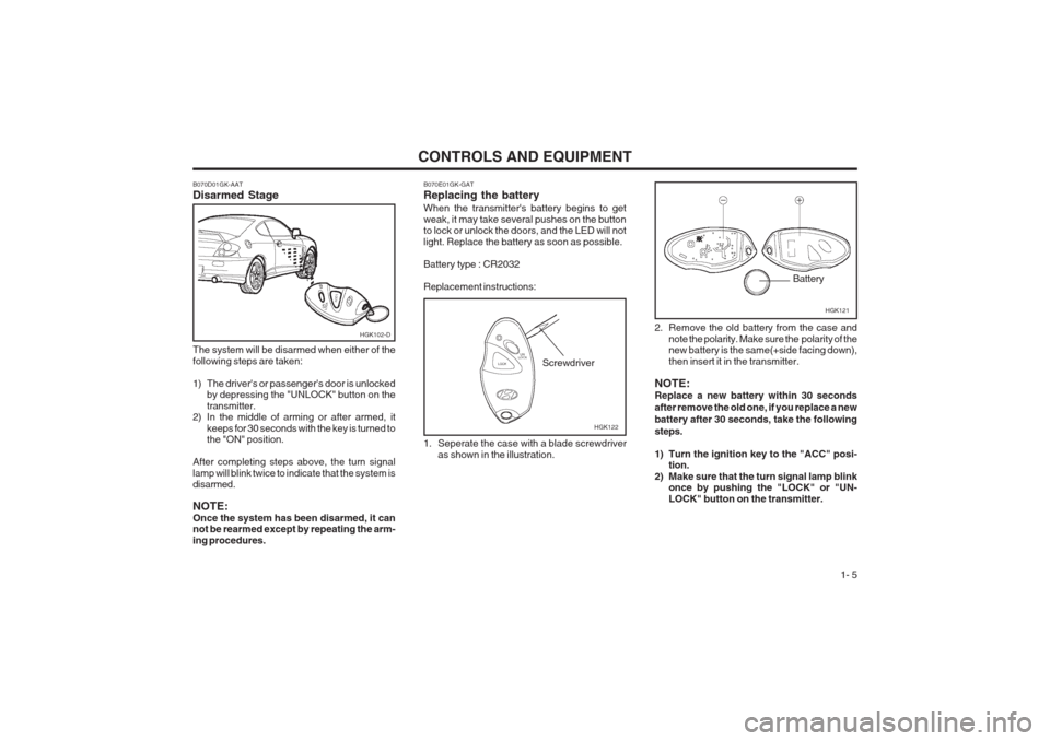
B070E01GK-GAT Replacing the battery When the transmitter's battery begins to get weak, it may take several pushes on the button to lock or unlock the doors, and the LED will not light. Replace the battery as soon as possible. Battery type : CR2032Replacement instructions:
1. Seperate the case with a blade screwdriveras shown in the illustration.
B070D01GK-AAT Disarmed Stage The system will be disarmed when either of the following steps are taken:
1) The driver's or passenger's door is unlocked
by depressing the "UNLOCK" button on the transmitter.
2) In the middle of arming or after armed, it
keeps for 30 seconds with the key is turned to the "ON" position.
After completing steps above, the turn signal lamp will blink twice to indicate that the system is disarmed. NOTE: Once the system has been disarmed, it can not be rearmed except by repeating the arm- ing procedures.
HGK122
Screwdriver 2. Remove the old battery from the case and
note the polarity. Make sure the polarity of the new battery is the same(+side facing down), then insert it in the transmitter.
NOTE: Replace a new battery within 30 seconds after remove the old one, if you replace a newbattery after 30 seconds, take the followingsteps.
1) Turn the ignition key to the "ACC" posi- tion.
2) Make sure that the turn signal lamp blink once by pushing the "LOCK" or "UN- LOCK" button on the transmitter.
HGK121
Battery
Page 29 of 140
CONTROLS AND EQUIPMENT1- 21
WARNING:
o When the SRS is activated, there may be aloud noise and fine dust will be releasedthroughout the vehicle. These conditions are normal and are not hazardous. How- ever, the fine dust generated during airbag deployment may cause skin irritation. Be sure to wash your hands and face thor- oughly with lukewarm water and a mild soap after an accident in which the airbags were deployed.
o The SRS can function only when the igni-
tion key is in the "ON" position. If the SRS SRI does not come on or illuminates continuously when the ignition key is turned to "ON", or continuously remains on after flashing for about 6 seconds when the ignition key is turned to the "ON" position, or after the engine is started, or comes on while driving, the SRS is not working properly. If this occurs, have your vehicle immediately inspected by your Hyundai dealer.
o Before you replace a fuse or disconnect a
battery terminal, turn the ignition key to the "LOCK" position or remove the igni- tion key. Never remove or replace the air bag related fuse(s) when the ignition key is in the "ON" position. Failure to heed this warning will cause the SRS SRI to illumi- nate.
FUD1115A
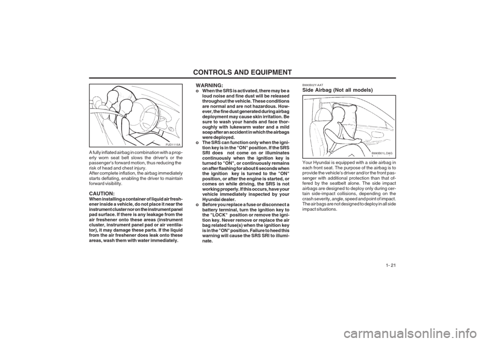
A fully inflated airbag in combination with a prop- erly worn seat belt slows the driver's or the passenger's forward motion, thus reducing the risk of head and chest injury. After complete inflation, the airbag immediately starts deflating, enabling the driver to maintain forward visibility. CAUTION: When installing a container of liquid air fresh- ener inside a vehicle, do not place it near the instrument cluster nor on the instrument panel pad surface. If there is any leakage from the air freshener onto these areas (instrument cluster, instrument panel pad or air ventila- tor), it may damage these parts. If the liquid from the air freshener does leak onto these areas, wash them with water immediately. Your Hyundai is equipped with a side airbag ineach front seat. The purpose of the airbag is to provide the vehicle's driver and/or the front pas- senger with additional protection than that of- fered by the seatbelt alone. The side impact airbags are designed to deploy only during cer- tain side-impact collisions, depending on the crash severity, angle, speed and point of impact. The air bags are not designed to deploy in all side impact situations.
B990B02Y-AAT Side Airbag (Not all models)
B990B01L.DAG
Page 39 of 140
CONTROLS AND EQUIPMENT1- 31
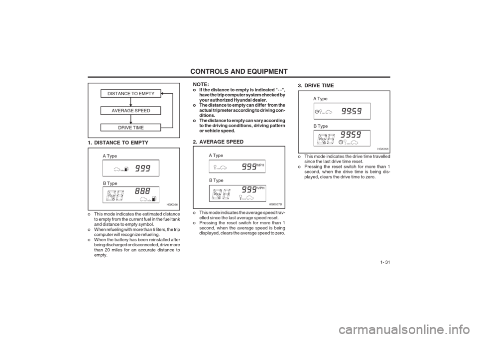
3. DRIVE TIME
HGK058
A Type
B Type
NOTE:
o If the distance to empty is indicated "- -", have the trip computer system checked byyour authorized Hyundai dealer.
o The distance to empty can differ from the
actual tripmeter according to driving con- ditions.
o The distance to empty can vary according to the driving conditions, driving pattern or vehicle speed.
2. AVERAGE SPEED
o This mode indicates the average speed trav- elled since the last average speed reset.
o Pressing the reset switch for more than 1
second, when the average speed is being displayed, clears the average speed to zero. HGK057B
A Type
B Type
1. DISTANCE TO EMPTY DISTANCE TO EMPTY
AVERAGE SPEED DRIVE TIME
o This mode indicates the estimated distanceto empty from the current fuel in the fuel tank and distance to empty symbol.
o When refueling with more than 6 liters, the trip computer will recognize refueling.
o When the battery has been reinstalled after being discharged or disconnected, drive more than 20 miles for an accurate distance to empty. HGK056
A Type
B Type
o This mode indicates the drive time travelled since the last drive time reset.
o Pressing the reset switch for more than 1 second, when the drive time is being dis- played, clears the drive time to zero.
Page 47 of 140
CONTROLS AND EQUIPMENT1- 39
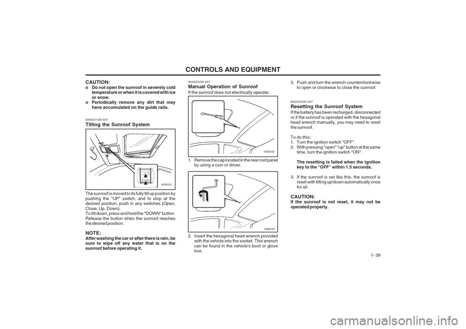
3. Push and turn the wrench counterclockwiseto open or clockwise to close the sunroof.
B460D02GK-AAT Manual Operation of Sunroof If the sunroof does not electrically operate:
HGK032
1. Remove the cap located in the rear roof panel by using a coin or driver.
2. Insert the hexagonal head wrench provided with the vehicle into the socket. This wrench can be found in the vehicle's boot or glove box.
HGK033
CAUTION:
o Do not open the sunroof in severely cold temperature or when it is covered with iceor snow.
o Periodically remove any dirt that may
have accumulated on the guide rails.
B460C01GK-GAT Tilting the Sunroof System
HGK031
The sunroof is moved to its fully tilt up position by pushing the "UP" switch, and to stop at the desired position, push in any switches (Open, Close, Up, Down). To tilt down, press and hold the "DOWN" button. Release the button when the sunroof reaches the desired position. NOTE: After washing the car or after there is rain, be sure to wipe off any water that is on the sunroof before operating it.
B460E02GK-GAT Resetting the Sunroof System If the battery has been recharged, disconnected or if the sunroof is operated with the hexagonal head wrench manually, you may need to reset the sunroof. To do this;
1. Turn the ignition switch "OFF".
2. With pressing "open" "up" button at the same time, turn the ignition switch "ON". The resetting is failed when the ignition key to the "OFF" within 1.5 seconds.
3. If the sunroof is set like this, the sunroof is reset with tilting up/down automatically oncefor all.
CAUTION: If the sunroof is not reset, it may not be operated properly.
Page 65 of 140
CONTROLS AND EQUIPMENT1- 57
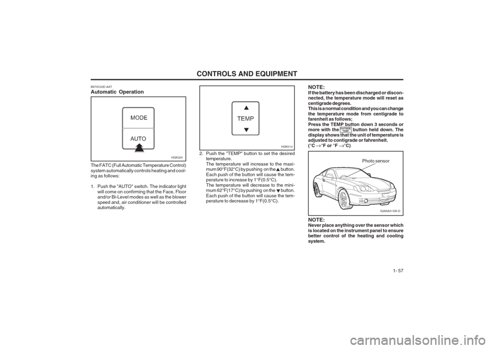
B970C02E-AAT Automatic Operation
HGK020
The FATC (Full Automatic Temperature Control) system automatically controls heating and cool- ing as follows:
1. Push the "AUTO" switch. The indicator light will come on confirming that the Face, Floor and/or Bi-Level modes as well as the blower speed and, air conditioner will be controlled automatically. 2. Push the "TEMP" button to set the desired
temperature. The temperature will increase to the maxi- mum 90°F(32°C) by pushing on the button. Each push of the button will cause the tem- perature to increase by 1°F(0.5°C). The temperature will decrease to the mini- mum 62°F(17°C) by pushing on the button. Each push of the button will cause the tem- perature to decrease by 1°F(0.5°C).
G280A01GK-D
Photo sensor
HGK014
NOTE: Never place anything over the sensor which is located on the instrument panel to ensure better control of the heating and cooling system.
NOTE:If the battery has been discharged or discon- nected, the temperature mode will reset as centigrade degrees. This is a normal condition and you can change the temperature mode from centigrade to farenheit as follows; Press the TEMP button down 3 seconds or more with the button held down. The display shows that the unit of temperature is adjusted to contigrade or fahrenheit. (°C °F or °F °C)
OUTSIDE
TEMP
Page 76 of 140
DRIVING YOUR HYUNDAI
2- 2
SC030A1-E BEFORE STARTING THE ENGINEBefore you start the engine, you should always:
1. Look around the vehicle to be sure there are
no flat tires, puddles of oil or water or otherindications of possible trouble.
2. After entering the car, check to be sure the parking brake is engaged.
3. Check that all windows, and lights are clean.
4. Check that the interior and exterior mirrors are clean and in position.
5. Check your seat, seatback and head re- straint to be sure they are in their proper positions.
6. Lock all the doors.
7. Fasten your seat belt and be sure that all other occupants have fastened theirs.
8. Turn off all lights and accessories that are
not needed.
9. When you turn the ignition switch to "ON' check that all appropriate warning lights areoperating and that you have sufficient fuel.
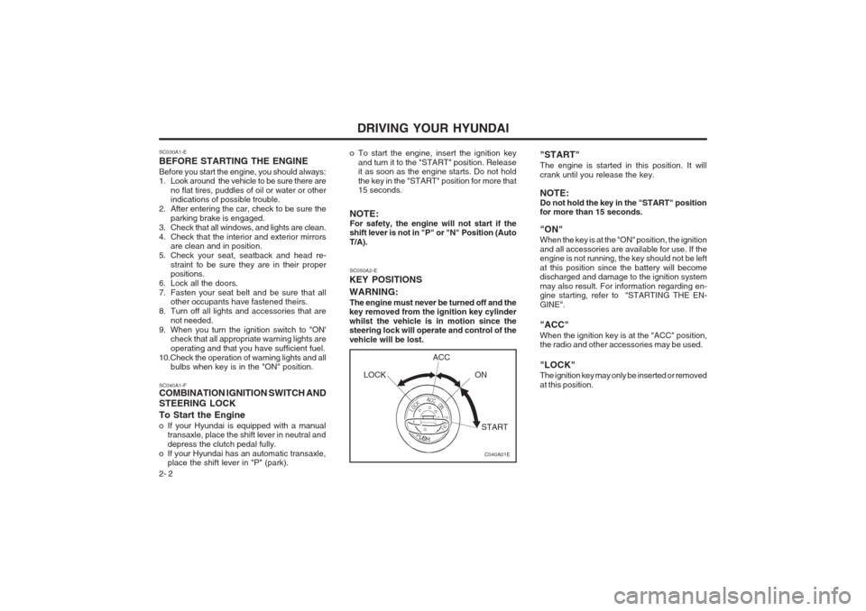
10.Check the operation of warning lights and all bulbs when key is in the "ON" position. o To start the engine, insert the ignition key
and turn it to the "START" position. Release it as soon as the engine starts. Do not hold the key in the "START" position for more that 15 seconds.
NOTE: For safety, the engine will not start if the shift lever is not in "P" or "N" Position (Auto T/A).
SC040A1-F COMBINATION IGNITION SWITCH AND STEERING LOCK To Start the Engine
o If your Hyundai is equipped with a manual transaxle, place the shift lever in neutral and depress the clutch pedal fully.
o If your Hyundai has an automatic transaxle, place the shift lever in "P" (park). SC050A2-E
KEY POSITIONS WARNING:
The engine must never be turned off and the
key removed from the ignition key cylinder whilst the vehicle is in motion since the steering lock will operate and control of the vehicle will be lost. "START" The engine is started in this position. It will crank until you release the key. NOTE: Do not hold the key in the "START" position for more than 15 seconds. "ON" When the key is at the "ON" position, the ignition and all accessories are available for use. If the engine is not running, the key should not be left at this position since the battery will become discharged and damage to the ignition system may also result. For information regarding en- gine starting, refer to "STARTING THE EN- GINE". "ACC" When the ignition key is at the "ACC" position, the radio and other accessories may be used. "LOCK" The ignition key may only be inserted or removed at this position.
C040A01E
LOCK
ACC
ON
START
Page 80 of 140
DRIVING YOUR HYUNDAI
2- 6 The first few shifts on a new vehicle, or if the
battery has been disconnected, may be somewhat abrupt. This is a normal condi- tion, and the shifting sequence will adjust after shifts are cycled a few times by the T.C.M (Transmission Control Module).
CAUTION:Never shift into "R" or "P" position while
the vehicle is moving.
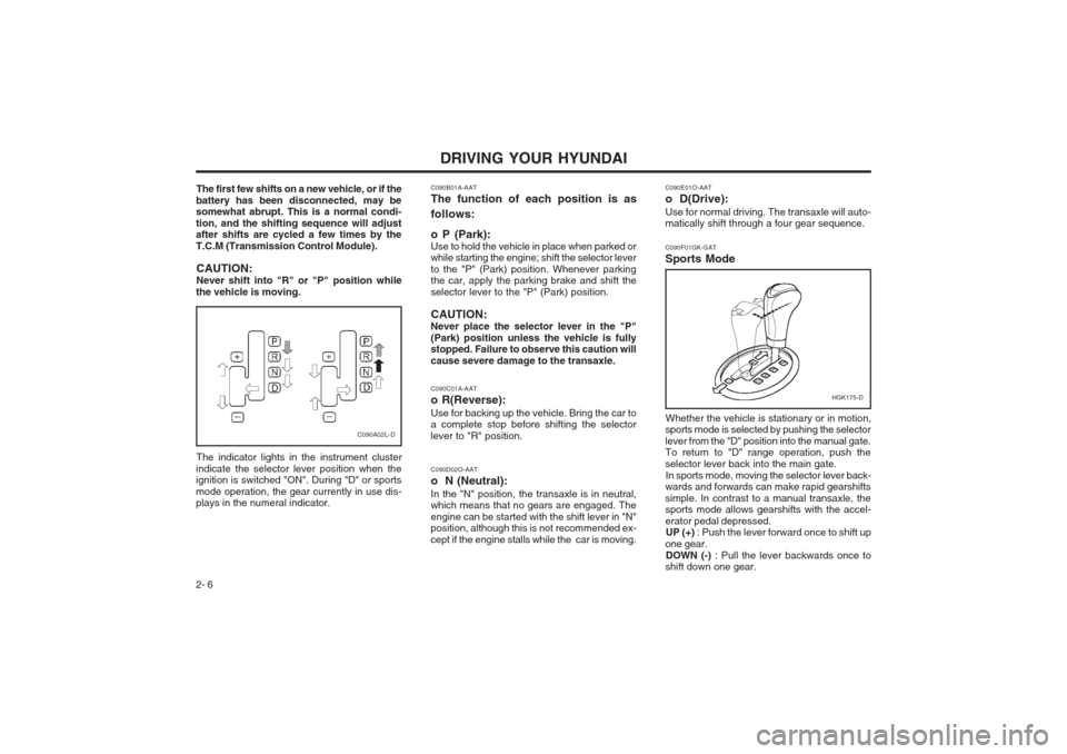
The indicator lights in the instrument cluster
indicate the selector lever position when the ignition is switched "ON". During "D" or sports mode operation, the gear currently in use dis- plays in the numeral indicator.
C090A02L-D C090F01GK-GAT Sports Mode
HGK175-D
Whether the vehicle is stationary or in motion,
sports mode is selected by pushing the selector lever from the "D" position into the manual gate. To return to "D" range operation, push the selector lever back into the main gate.
In sports mode, moving the selector lever back-
wards and forwards can make rapid gearshiftssimple. In contrast to a manual transaxle, the sports mode allows gearshifts with the accel- erator pedal depressed. UP (+) : Push the lever forward once to shift up
one gear. DOWN (-) : Pull the lever backwards once to
shift down one gear.
C090E01O-AAT
o D(Drive):Use for normal driving. The transaxle will auto- matically shift through a four gear sequence.
C090B01A-AAT The function of each position is as follows: o P (Park): Use to hold the vehicle in place when parked or while starting the engine; shift the selector lever to the "P" (Park) position. Whenever parking the car, apply the parking brake and shift the selector lever to the "P" (Park) position. CAUTION: Never place the selector lever in the "P"(Park) position unless the vehicle is fully stopped. Failure to observe this caution will cause severe damage to the transaxle. C090C01A-AAT o R(Reverse):Use for backing up the vehicle. Bring the car to a complete stop before shifting the selector lever to "R" position. C090D02O-AAT o N (Neutral):In the "N" position, the transaxle is in neutral, which means that no gears are engaged. The engine can be started with the shift lever in "N" position, although this is not recommended ex- cept if the engine stalls while the car is moving.
Page 85 of 140
DRIVING YOUR HYUNDAI 2- 11
o Remember, your car does not require ex-
tended warm-up. As soon as the engine is running smoothly, you can drive away. In very cold weather, however, give your en- gine a slightly longer warm-up period.
o Don't "lug" or "over-rev" the engine. Lugging
is driving too slowly in too high a gearresulting in the engine bucking. If this hap- pens to you, shift to a lower gear. Over-revving is racing the engine beyond its safe limit. This can be avoided by shifting at the recommended speeds.
o Use your air conditioning sparingly. The air conditioning system is operated by the en-gine power so your fuel economy is reduced when you use it.
SC160A1-F SMOOTH CORNERINGAvoid braking or gear changing in corners, especially when roads are wet. Ideally, corners should always be taken under gentle accelera- tion. If you follow these suggestions, tire wear will be held to a minimum. SC170A1-E WINTER MOTORINGThe onset of winter conditions subject motor vehicles to greater operating demands. There- fore, the following suggestions will assist in maintaining peak performance and reliability during these periods: ZC170B1-E Electrical SystemWinter conditions impose severe demands upon vehicle electrical systems, particularly the charg- ing circuit. The battery condition and perfor- mance along with the alternator performance and drive belt condition should be checked prior to the onset of winter. ZC170C1-E Anti-freeze/Corrosion inhibitorThe cooling system must always contain an Ethylene-Glycol based anti-freeze solution. The system is filled during manufacture with solu- tion of the correct strength which should be checked before the onset of winter and adjust- ed or changed as required. NOTE: The anti-freeze solution contains a corro- sion inhibitor to prevent degradation of the aluminum castings contained within the engine. Therefore, never, drain the system and refill with water only. In addition, anti-freeze solution must ALWAYS be used in vehicles fitted with air conditioning, to prevent the heater matrix from freezing and subsequently bursting with the refrigeration sys- tem in use.
ZC170D1-E Door LocksShould the door lock mechanism become fro- zen, a proprietary lock de-icer should be used. Alternatively, warming the door key may thaw the door lock. However, the key should be handled carefully to avoid burning the fingers. Never attempt to thaw a frozen door lock using hot water, since the water will eventually freeze and compound the problem. NOTE: The proper temperature for using the immo-bilizer key is from -40°F (-40°C) to 176°F (80°C). If you heat the immobilizer key over 176°F (80°C) to open the frozen lock, it may cause damage to the transponder in its head. SC170E1-E Windscreen Washers and WipersThe windscreen washer bottle should be filled with a solution of water and a proprietary winter screen wash additive. The windscreen wipers should not be used if the blades are frozen to the windscreen or if they are covered with snow, before this is removed. NOTE: Never allow undiluted screen washer fluid additive to spill upon the paintwork or use engine coolant anti-freeze since damage to the paintwork may result.
Page 89 of 140
3-1
IN CASE OF EMERGENCY
that the transmission selector is at the "P" or"N" position.
2. Check the battery terminals and connections
to ensure that these are clean and also tight.
3. If the ignition warning lamps dim when the
engine is cranked and the battery terminals have been checked, a discharged battery is indicated.
4. Do not attempt to push or tow start the ve-
hicle, refer to "Jump Starting" for information regarding engine starting when the battery is discharged.
SD000A1-E
3. IN CASE OF EMER-
GENCY
SD020A1-E IF THE ENGINE WILL NOT START Seek assistance from the nearest Hyundai dealer with regard to the method of ignition and fuel system diagnosis. CAUTION: If the engine refuses to start, no attempt should be made to push or tow start the vehicle. Vehicles with automatic transmis- sion or fuel injection will not be able to be started in this manner since no drive is trans- mitted through the automatic transmission whilst the engine is not running, and in the case of fuel injected derivatives, the fuel pump will not operate under tow start conditions. In addition, if the vehicle is equipped with an exhaust catalyst, damage to the catalyst may result if the vehicle is tow started. SD020B1-E IF THE ENGINE CANNOT BECRANKED
1. If the vehicle is fitted with manual transmis- sion, ensure that the clutch pedal is depressedwhilst cranking the engine. If the vehicle is fitted with automatic transmission, ensure SD020C1-F If Engine Turns Over Normally but Does Not Start
1. Check fuel Level
2. Check all connectors at ignition coil and spark
plugs.Replace any that may be disconnected or loose.
3. Check fuel line in the engine room.
4. If engine still refuses to start, call a Hyundai dealer or seek other qualified assistance.
AD020D1-A If Engine Stalls While Driving
1. Reduce your speed gradually, keeping a straight line. Move cautionsly off the road to a safe place.
2. Turn on your emergency flashers.
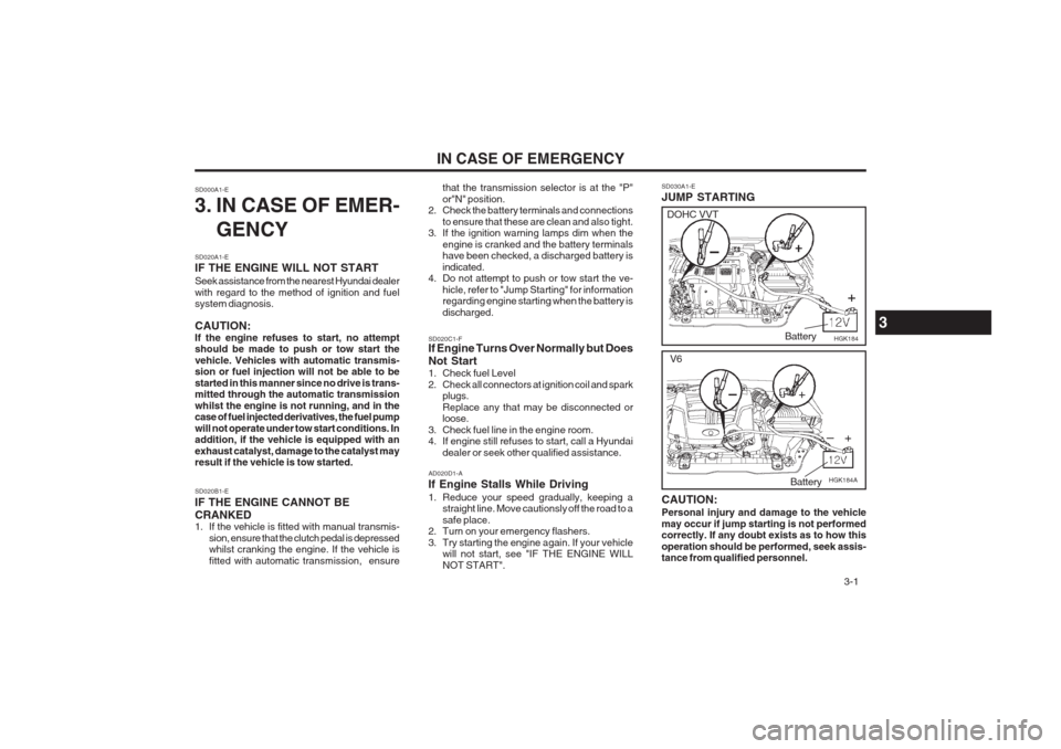
3. Try starting the engine again. If your vehicle will not start, see "IF THE ENGINE WILLNOT START". SD030A1-E JUMP STARTING
3
HGK184
Battery
DOHC VVT
HGK184A
V6
Battery
CAUTION: Personal injury and damage to the vehicle may occur if jump starting is not performed correctly. If any doubt exists as to how this operation should be performed, seek assis- tance from qualified personnel.
Page 90 of 140
IN CASE OF EMERGENCY
3-2 4. Check to see if the water pump drive belt is
missing. If it is not missing, check to see that it is tight. If the drive belt seems to be satisfac- tory, check for coolant leaking from the radia- tor, hoses or under the car. (If the air condi- tioning had been in use, it is normal for cold water to be draining from it).
WARNING: Whilst the engine is running, keep hands and clothing away from moving parts such as the fan and drive belts to prevent injury.
5. If the water pump drive belt is broken or coolant is leaking out, stop the engine imme- diately and call the nearest Hyundai dealer for assistance.
WARNING:Do not remove the radiator cap when the engine is hot since steam and boiling water may be ejected from the radiator resulting in burns or scalding.
6. If the cause of the overheating cannot be found, wait until the engine temperature has returned to normal. Then, if coolant has been lost, carefully remove the radiator cap and add water to bring the fluid level in the reser- voir up to the base of the radiator fill opening. Fill the coolant expansion tank to the halfway mark.
WARNING: Motor vehicle batteries contain sulphuric acid and emit hydrogen gas. Protective clothing should be worn and care exercised to prevent the acid from coming into contact with skin or clothing and the vehicle. Naked lights should not be permitted in the vicinity of the battery. Care should be exercised to prevent sparks occurring during connection. If acid acciden- tally comes into contact with skin or eyes, the affected area should immediately be flushed with copious amounts of water and medical assistance sought.
1. Ensure that the booster battery is 12 volt type.
If the booster battery is installed in another vehicle, ensure that the two vehicles are not touching.
2. Turn off all unnecessary electrical equipment in both vehicles.
3. Ensure that the engine of the vehicle provid- ing the jump start is running prior to connec- tion of the jump cables.
4. Connect the red jump cable to the positive (+)
terminal of the booster battery and the other end to the positive (+) terminal of the dis- charged battery.
5. Attach the black jump cable to the negative
(-) terminal of the booster battery, and the other end to a ground point within the engine compartment of the vehicle with the flat bat- tery. Do not connect to the negative battery terminal of the flat battery since sparks may be generated with the subsequent risk of explosion. 6. Raise the booster vehicle engine speed to
2,000 r.p.m. and start the engine of the vehi- cle with the flat battery.
7. Remove jump cables in the reverse order of installation (black cable first).
CAUTION: If the jump cable is incorrectly installed, dam- age to the vehicle electrical system may oc- cur, in particular the electronic components such as the Fuel Injection system computer and the Automatic Transmission computer. The battery must never be disconnected whilst the engine is running. SD040A1-E IF THE ENGINE OVERHEATSIf the temperature gauge indicates overheating:
1. Pull off the road and stop as soon as it is safe to do so.
2. Place the gear selector lever in "P" (auto- matic), or neutral (manual transaxle) and set the parking brake. If the air conditioning is on, turn it off.
3. If coolant is running out under the car or steam is coming out from under the bonnet stop the engine. Do not open the bonnet until the cool-ant has stopped running or the steam- ing has stopped. If there is no visible loss of coolant and no steam, leave the engine run- ning and check to be sure the engine cooling fan is operating. If the fan is not running, turn the engine off.