clock Hyundai Coupe 2002 Owner's Manual
[x] Cancel search | Manufacturer: HYUNDAI, Model Year: 2002, Model line: Coupe, Model: Hyundai Coupe 2002Pages: 140, PDF Size: 1.45 MB
Page 30 of 140
CONTROLS AND EQUIPMENT
1- 22 WARNING:
o Extreme Hazard! Do not use a rearward
facing child restraint on a seat protectedby an airbag in front of it!
o Modification to SRS components or wir-ing,
including the addition of any kind of badges to the pad cover or modifications to the body structure, can adversely affect SRS performance and lead to possible injury.
o For cleaning the horn pad, use only a soft, dry cloth or one which has been moist- ened with plain water. Solvents or clean- ers could adversely affect the airbag cover and proper deployment of the system.
o No objects should be placed over or near
the airbag module on the steering wheel, because any such object could cause harm if the vehicle is in a crash severe enough to cause the airbag to inflate.
o If the airbag inflates, it must be replaced by an authorized Hyundai dealer.
o Do not tamper with or disconnect SRS wiring, or other components of the SRS system. Doing so could result in injury, due to accidental firing of the airbag or by rendering the SRS inoperative.
o If components of the airbag system must
be discarded, or if the vehicle must be scrapped, certain safety precautions must be observed. Your Hyundai dealer knows these precautions and can give you the necessary information. Failure to follow these precautions and procedures could increase the risk of personal injury.
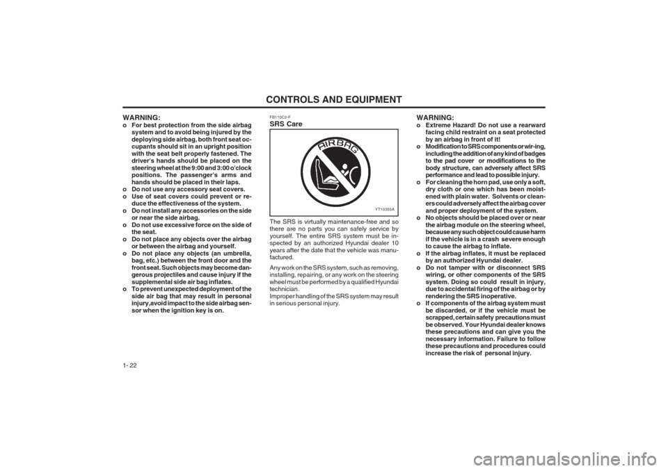
WARNING:
o For best protection from the side airbag
system and to avoid being injured by thedeploying side airbag, both front seat oc- cupants should sit in an upright position with the seat belt properly fastened. The driver's hands should be placed on the steering wheel at the 9:00 and 3:00 o'clock positions. The passenger's arms and hands should be placed in their laps.
o Do not use any accessory seat covers.
o Use of seat covers could prevent or re- duce the effectiveness of the system.
o Do not install any accessories on the side or near the side airbag.
o Do not use excessive force on the side of the seat.
o Do not place any objects over the airbag or between the airbag and yourself.
o Do not place any objects (an umbrella, bag, etc.) between the front door and thefront seat. Such objects may become dan- gerous projectiles and cause injury if the supplemental side air bag inflates.
o To prevent unexpected deployment of the
side air bag that may result in personal injury,avoid impact to the side airbag sen- sor when the ignition key is on. FB110C2-F SRS Care
YT10355A
The SRS is virtually maintenance-free and so there are no parts you can safely service by yourself. The entire SRS system must be in- spected by an authorized Hyundai dealer 10 years after the date that the vehicle was manu- factured. Any work on the SRS system, such as removing, installing, repairing, or any work on the steering wheel must be performed by a qualified Hyundai technician. Improper handling of the SRS system may result in serious personal injury.
Page 32 of 140
CONTROLS AND EQUIPMENT
1- 24 8
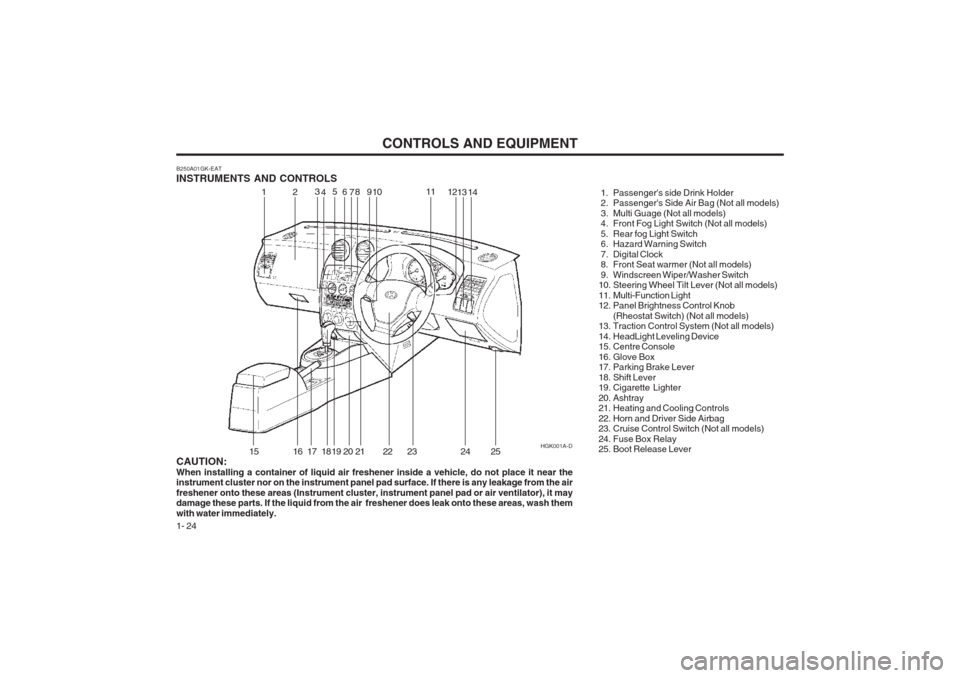
B250A01GK-EAT INSTRUMENTS AND CONTROLS
1. Passenger's side Drink Holder
2. Passenger's Side Air Bag (Not all models)
3. Multi Guage (Not all models)
4. Front Fog Light Switch (Not all models)
5. Rear fog Light Switch
6. Hazard Warning Switch
7. Digital Clock
8. Front Seat warmer (Not all models)
9. Windscreen Wiper/Washer Switch
10. Steering Wheel Tilt Lever (Not all models)
11. Multi-Function Light
12. Panel Brightness Control Knob(Rheostat Switch) (Not all models)
13. Traction Control System (Not all models)
14. HeadLight Leveling Device
15. Centre Console
16. Glove Box
17. Parking Brake Lever
18. Shift Lever
19. Cigarette Lighter
20. Ashtray
21. Heating and Cooling Controls
22. Horn and Driver Side Airbag
23. Cruise Control Switch (Not all models)
24. Fuse Box Relay
25. Boot Release Lever
CAUTION: When installing a container of liquid air freshener inside a vehicle, do not place it near the instrument cluster nor on the instrument panel pad surface. If there is any leakage from the air freshener onto these areas (Instrument cluster, instrument panel pad or air ventilator), it may damage these parts. If the liquid from the air freshener does leak onto these areas, wash them with water immediately. HGK001A-D
12
3
4 5
69 10 11
1213
15
16 17 18 19 20 21 22 23 24
714
25
Page 44 of 140
CONTROLS AND EQUIPMENT
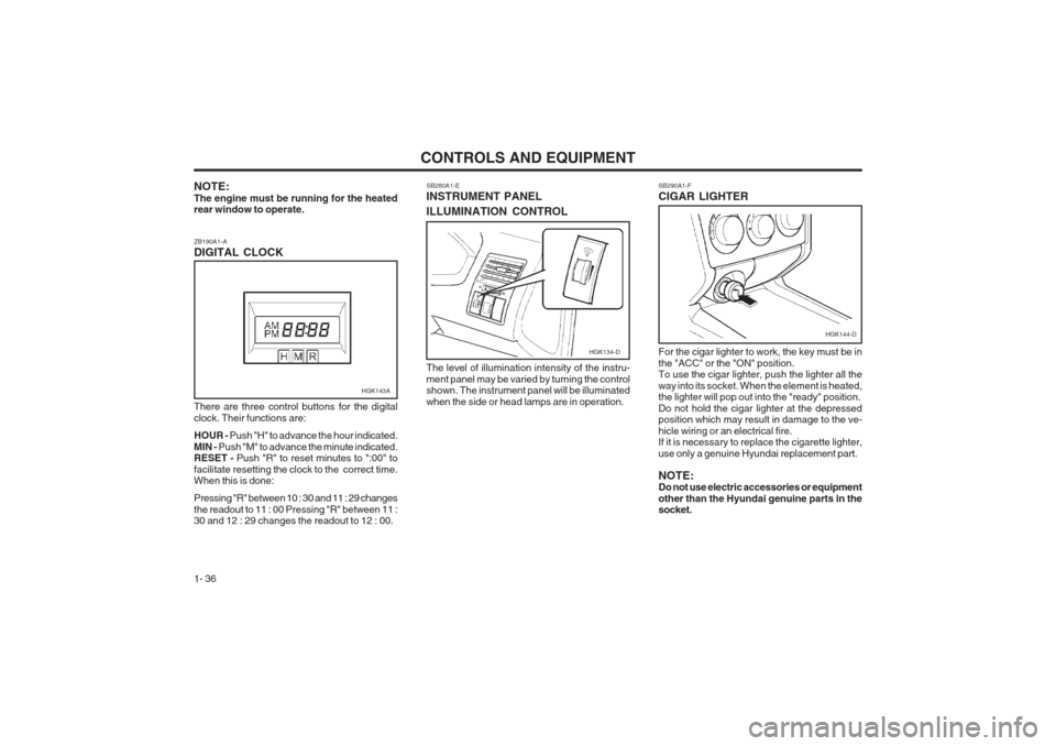
1- 36 SB290A1-F CIGAR LIGHTER
NOTE: The engine must be running for the heated rear window to operate. ZB190A1-A DIGITAL CLOCK SB280A1-EINSTRUMENT PANEL ILLUMINATION CONTROL
There are three control buttons for the digital clock. Their functions are: HOUR - Push "H" to advance the hour indicated.
MIN - Push "M" to advance the minute indicated.
RESET - Push "R" to reset minutes to ":00" to
facilitate resetting the clock to the correct time. When this is done: Pressing "R" between 10 : 30 and 11 : 29 changes the readout to 11 : 00 Pressing "R" between 11 : 30 and 12 : 29 changes the readout to 12 : 00. The level of illumination intensity of the instru- ment panel may be varied by turning the control shown. The instrument panel will be illuminated when the side or head lamps are in operation.
For the cigar lighter to work, the key must be inthe "ACC" or the "ON" position. To use the cigar lighter, push the lighter all the way into its socket. When the element is heated, the lighter will pop out into the "ready" position. Do not hold the cigar lighter at the depressed position which may result in damage to the ve- hicle wiring or an electrical fire. If it is necessary to replace the cigarette lighter, use only a genuine Hyundai replacement part. NOTE: Do not use electric accessories or equipment other than the Hyundai genuine parts in the socket.
HGK143A
HGK134-D
HGK144-D
Page 47 of 140
CONTROLS AND EQUIPMENT1- 39
3. Push and turn the wrench counterclockwiseto open or clockwise to close the sunroof.
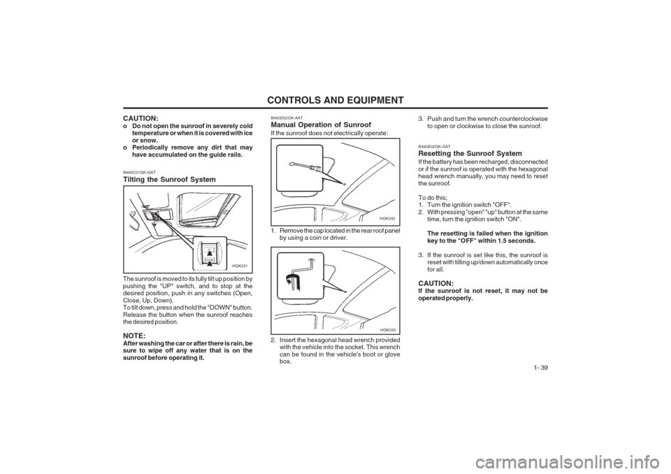
B460D02GK-AAT Manual Operation of Sunroof If the sunroof does not electrically operate:
HGK032
1. Remove the cap located in the rear roof panel by using a coin or driver.
2. Insert the hexagonal head wrench provided with the vehicle into the socket. This wrench can be found in the vehicle's boot or glove box.
HGK033
CAUTION:
o Do not open the sunroof in severely cold temperature or when it is covered with iceor snow.
o Periodically remove any dirt that may
have accumulated on the guide rails.
B460C01GK-GAT Tilting the Sunroof System
HGK031
The sunroof is moved to its fully tilt up position by pushing the "UP" switch, and to stop at the desired position, push in any switches (Open, Close, Up, Down). To tilt down, press and hold the "DOWN" button. Release the button when the sunroof reaches the desired position. NOTE: After washing the car or after there is rain, be sure to wipe off any water that is on the sunroof before operating it.
B460E02GK-GAT Resetting the Sunroof System If the battery has been recharged, disconnected or if the sunroof is operated with the hexagonal head wrench manually, you may need to reset the sunroof. To do this;
1. Turn the ignition switch "OFF".
2. With pressing "open" "up" button at the same time, turn the ignition switch "ON". The resetting is failed when the ignition key to the "OFF" within 1.5 seconds.
3. If the sunroof is set like this, the sunroof is reset with tilting up/down automatically oncefor all.
CAUTION: If the sunroof is not reset, it may not be operated properly.
Page 54 of 140
CONTROLS AND EQUIPMENT
1- 46
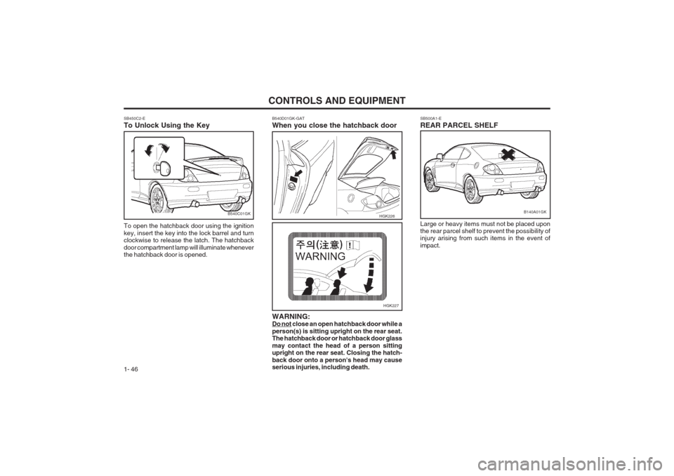
SB450C2-E To Unlock Using the Key To open the hatchback door using the ignition key, insert the key into the lock barrel and turn clockwise to release the latch. The hatchback door compartment lamp will illuminate whenever the hatchback door is opened.
SB500A1-E REAR PARCEL SHELF Large or heavy items must not be placed upon the rear parcel shelf to prevent the possibility ofinjury arising from such items in the event of impact.
B540C01GK
B540D01GK-GAT
When you close the hatchback door
HGK226
HGK227
WARNING:
Do not close an open hatchback door while a person(s) is sitting upright on the rear seat. The hatchback door or hatchback door glass may contact the head of a person sitting upright on the rear seat. Closing the hatch- back door onto a person's head may cause serious injuries, including death.
B140A01GK
Page 74 of 140
CONTROLS AND EQUIPMENT
1- 66
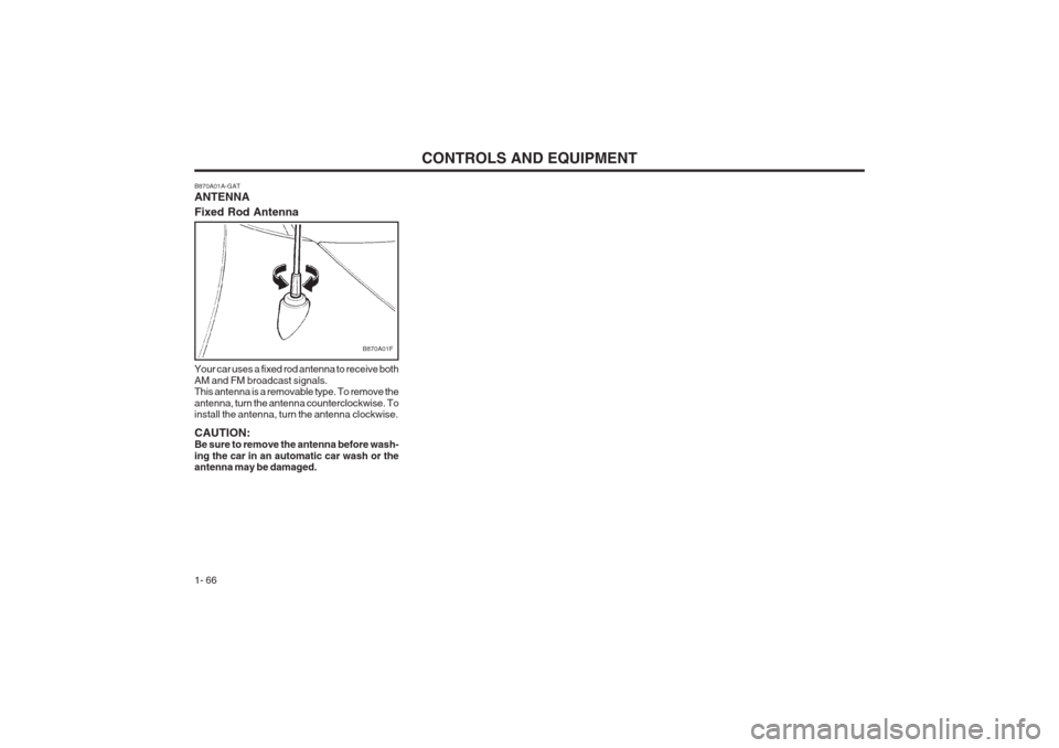
B870A01A-GAT ANTENNA Fixed Rod Antenna Your car uses a fixed rod antenna to receive both AM and FM broadcast signals. This antenna is a removable type. To remove the antenna, turn the antenna counterclockwise. To install the antenna, turn the antenna clockwise. CAUTION: Be sure to remove the antenna before wash- ing the car in an automatic car wash or the antenna may be damaged.
B870A01F
Page 78 of 140
DRIVING YOUR HYUNDAI
2- 4 CAUTION:
o Do not attempt to engage reverse gear
when the car is in motion.
o To avoid damaging the selector mecha- nism, do not use the gear shift lever as a hand rest. Release the lever immediately the shift is completed.
o To avoid premature clutch wear, do not use the clutch pedal as a foot rest, and donot hold the vehicle on a gradient using the clutch.
o Ensure that the engine is not over-revved by upshifting before the tachometer needleenters the red zone.
o Do not coast with the shift lever at the neutral position.
o When descending long gradients, make use of the engine braking to assist thefootbrake to avoid brake fade or over- heating.
o When slippery conditions are encountered, increased caution should be exercisedwhen gear changing, braking or ac- celerating. Abrupt changes in speed may cause a loss of traction or control of the vehicle.
o The starter motor will not operate unless the clutch pedal is depressed whilst theengine is being started.
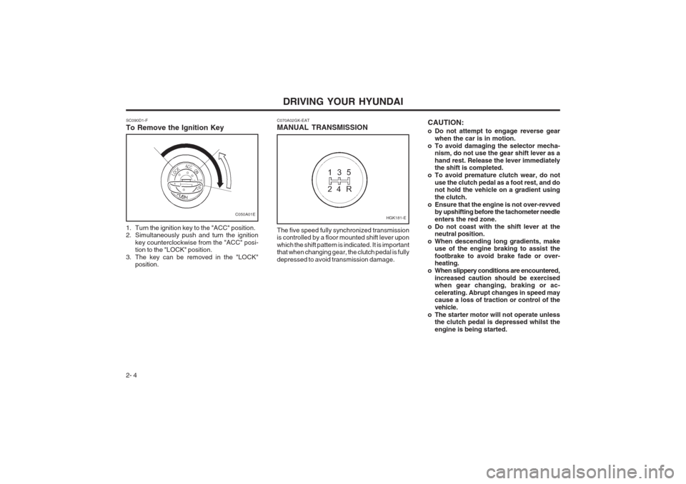
C070A02GK-EAT MANUAL TRANSMISSION The five speed fully synchronized transmission is controlled by a floor mounted shift lever upon which the shift pattern is indicated. It is important that when changing gear, the clutch pedal is fully depressed to avoid transmission damage.
SC090D1-F To Remove the Ignition Key
1. Turn the ignition key to the "ACC" position.
2. Simultaneously push and turn the ignition
key counterclockwise from the "ACC" posi-tion to the "LOCK" position.
3. The key can be removed in the "LOCK" position.
C050A01EHGK181-E
Page 92 of 140
IN CASE OF EMERGENCY
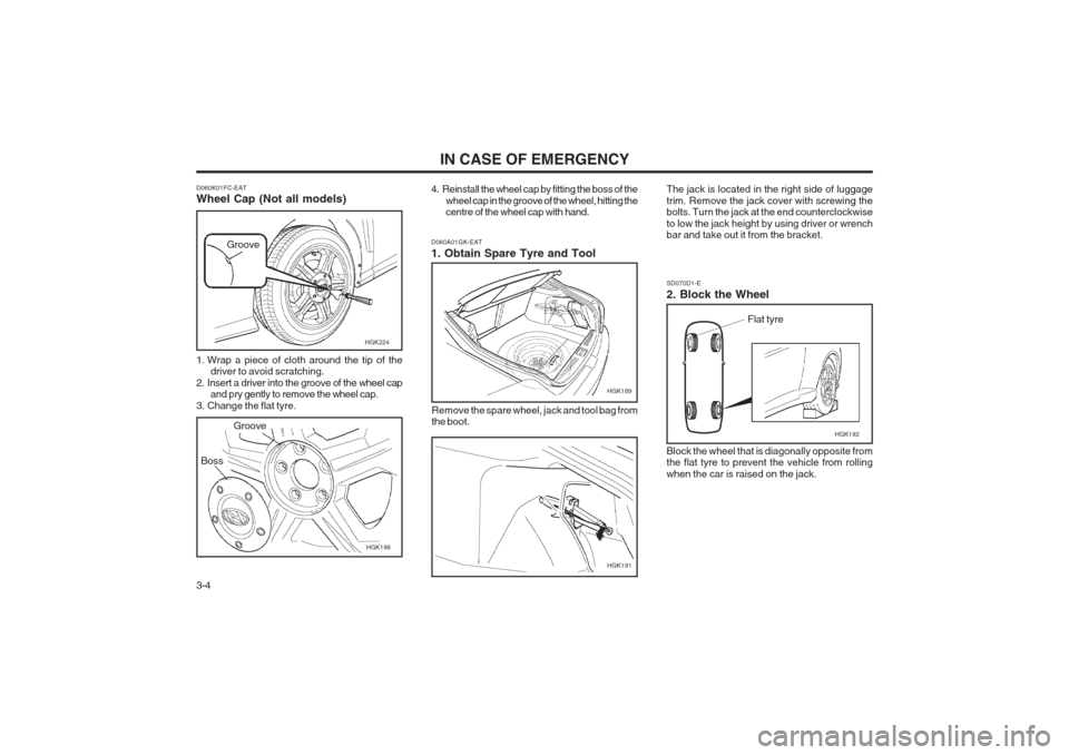
3-4 Remove the spare wheel, jack and tool bag from the boot.
SD070D1-E 2. Block the Wheel Block the wheel that is diagonally opposite from the flat tyre to prevent the vehicle from rolling when the car is raised on the jack.
D060A01GK-EAT 1. Obtain Spare Tyre and Tool
D060K01FC-EAT Wheel Cap (Not all models)
1. Wrap a piece of cloth around the tip of the
driver to avoid scratching.
2. Insert a driver into the groove of the wheel cap and pry gently to remove the wheel cap.
3. Change the flat tyre. 4. Reinstall the wheel cap by fitting the boss of the
wheel cap in the groove of the wheel, hitting the
centre of the wheel cap with hand.
Boss
HGK196
HGK224
Groove
Groove
HGK189
HGK191
The jack is located in the right side of luggage trim. Remove the jack cover with screwing the bolts. Turn the jack at the end counterclockwise to low the jack height by using driver or wrench bar and take out it from the bracket.
Flat tyre
HGK192
Page 93 of 140
3-5
IN CASE OF EMERGENCY
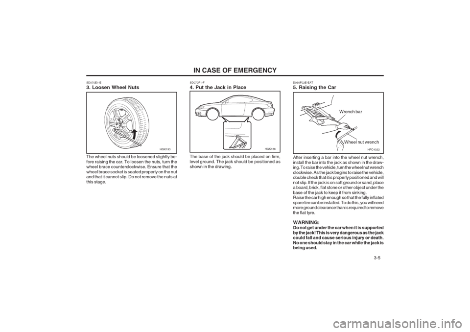
SD070E1-E 3. Loosen Wheel Nuts The wheel nuts should be loosened slightly be- fore raising the car. To loosen the nuts, turn the wheel brace counterclockwise. Ensure that the wheel brace socket is seated properly on the nut and that it cannot slip. Do not remove the nuts at this stage. SD070F1-F 4. Put the Jack in Place The base of the jack should be placed on firm, level ground. The jack should be positioned as shown in the drawing.
HGK193HGK186
D060F02E-EAT 5. Raising the Car After inserting a bar into the wheel nut wrench, install the bar into the jack as shown in the draw- ing. To raise the vehicle, turn the wheel nut wrench clockwise. As the jack begins to raise the vehicle, double check that it is properly positioned and will
not slip. If the jack is on soft ground or
sand, place
a board, brick, flat stone or other object under thebase of the jack to keep it from sinking. Raise the car high enough so that the fully inflated spare tire can be installed. To do this, you will need more ground clearance than is required to remove
the flat tyre. WARNING: Do not get under the car when it is supported by the jack! This is very dangerous as the jack could fall and cause serious injury or death. No one should stay in the car while the jack is being used.
HFC4022
Wrench bar
Wheel nut wrench
Page 95 of 140
3-7
IN CASE OF EMERGENCY
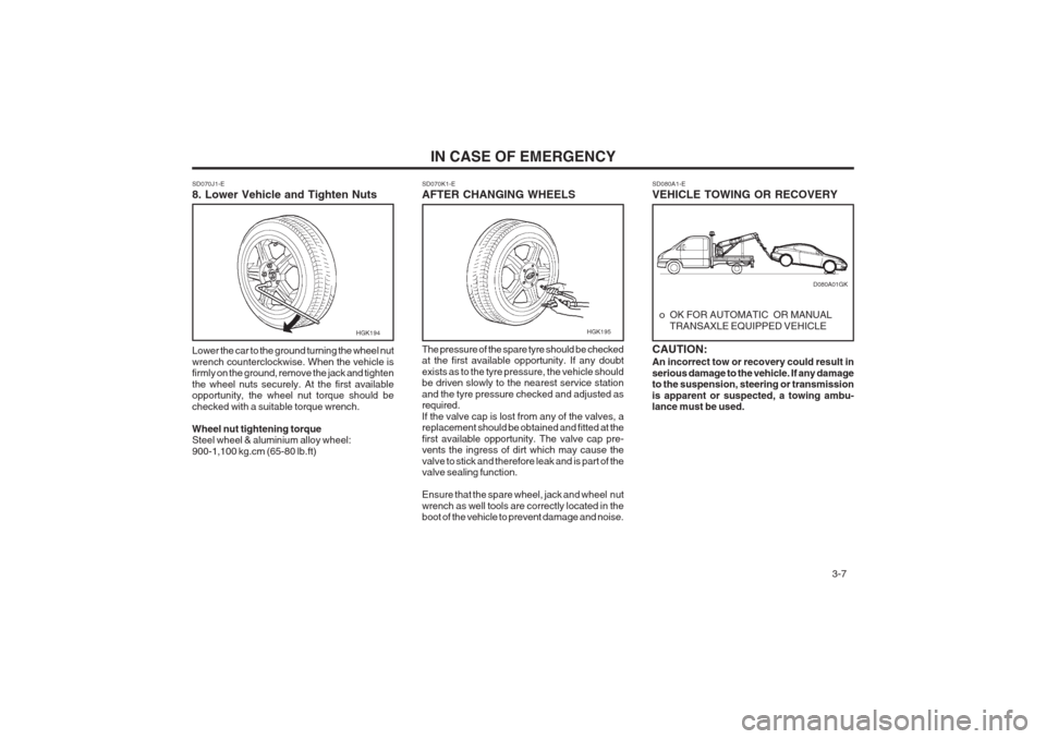
SD080A1-E VEHICLE TOWING OR RECOVERY
o OK FOR AUTOMATIC OR MANUALTRANSAXLE EQUIPPED VEHICLE
CAUTION: An incorrect tow or recovery could result in serious damage to the vehicle. If any damage to the suspension, steering or transmission is apparent or suspected, a towing ambu- lance must be used.
HGK194
SD070J1-E 8. Lower Vehicle and Tighten Nuts Lower the car to the ground turning the wheel nut wrench counterclockwise. When the vehicle is firmly on the ground, remove the jack and tighten the wheel nuts securely. At the first available opportunity, the wheel nut torque should be checked with a suitable torque wrench. Wheel nut tightening torque Steel wheel & aluminium alloy wheel: 900-1,100 kg.cm (65-80 lb.ft) SD070K1-E AFTER CHANGING WHEELS The pressure of the spare tyre should be checked at the first available opportunity. If any doubt exists as to the tyre pressure, the vehicle should be driven slowly to the nearest service station and the tyre pressure checked and adjusted as required. If the valve cap is lost from any of the valves, a replacement should be obtained and fitted at the first available opportunity. The valve cap pre- vents the ingress of dirt which may cause the valve to stick and therefore leak and is part of the valve sealing function. Ensure that the spare wheel, jack and wheel nut wrench as well tools are correctly located in the boot of the vehicle to prevent damage and noise.
D080A01GK
HGK195