radiator Hyundai Coupe 2002 Owner's Manual
[x] Cancel search | Manufacturer: HYUNDAI, Model Year: 2002, Model line: Coupe, Model: Hyundai Coupe 2002Pages: 140, PDF Size: 1.45 MB
Page 37 of 140
CONTROLS AND EQUIPMENT1- 29
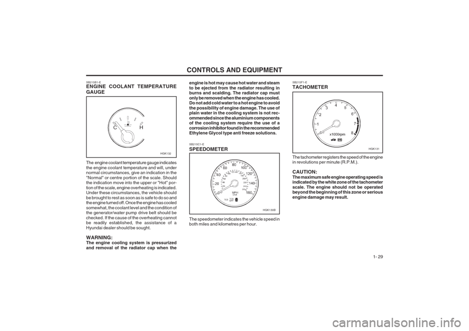
SB215F1-E TACHOMETER
SB215B1-E ENGINE COOLANT TEMPERATURE GAUGE engine is hot may cause hot water and steam to be ejected from the radiator resulting in burns and scalding. The radiator cap must only be removed when the engine has cooled. Do not add cold water to a hot engine to avoid the possibility of engine damage. The use of plain water in the cooling system is not rec- ommended since the aluminium components of the cooling system require the use of a corrosion inhibitor found in the recommended Ethylene Glycol type anti freeze solutions.
The engine coolant temperature gauge indicates the engine coolant temperature and will, under normal circumstances, give an indication in the "Normal" or centre portion of the scale. Should the indication move into the upper or "Hot" por- tion of the scale, engine overheating is indicated. Under these circumstances, the vehicle should be brought to rest as soon as is safe to do so and the engine turned off. Once the engine has cooled somewhat, the coolant level and the condition of the generator/water pump drive belt should be checked. If the cause of the overheating cannot be readily established, the assistance of a Hyundai dealer should be sought. WARNING: The engine cooling system is pressurized and removal of the radiator cap when the The tachometer registers the speed of the engine in revolutions per minute (R.P.M.). CAUTION: The maximum safe engine operating speed is indicated by the white zone of the tachometer scale. The engine should not be operated beyond the beginning of this zone or serious engine damage may result.
SB215C1-E SPEEDOMETER The speedometer indicates the vehicle speed in both miles and kilometres per hour.
HGK132HGK131
HGK130B
Page 53 of 140
CONTROLS AND EQUIPMENT1- 45
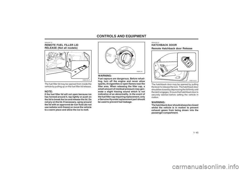
SB450A2-E HATCHBACK DOOR Remote Hatchback door Release The hatchback door may be opened by pulling the lever to release the lock. The hatchback door should be closed by depressing the lid firmly until the latch engages. Ensure that hatchback door is securely latched before setting the vehicle in motion. WARNING: The hatchback door should always be closed whilst the vehicle is in motion to prevent exhaust gases from being drawn into the passenger compartment.
HGK103-D
SB440A1-E REMOTE FUEL FILLER LID RELEASE (Not all models) The fuel filler lid may be opened from inside the vehicle by pulling up on the fuel filler lid release. NOTE: If the fuel filler lid will not open because ice has formed around it, tap lightly or push on the lid to break the ice and release the lid. Do not pry on the lid. If necessary, spray around the lid with an approved de-icer fluid (do not use radiator anti-freeze) or move the vehicle to a warm place and allow the ice to melt.
HGK105-D
HGK124
WARNING: Fuel vapours are dangerous. Before refuel- ling, turn off the engine and never allow sparks, lit cigarettes or open flames near the filler area. When releasing the filler cap, a small amount of residual pressure may gen- erate a slight hissing sound which is not indicative of an abnormality. In the event of the fuel filler cap requiring replacement, only a Genuine Hyundai replacement part should be used to prevent fuel leakage.
Page 90 of 140
IN CASE OF EMERGENCY
3-2 4. Check to see if the water pump drive belt is
missing. If it is not missing, check to see that it is tight. If the drive belt seems to be satisfac- tory, check for coolant leaking from the radia- tor, hoses or under the car. (If the air condi- tioning had been in use, it is normal for cold water to be draining from it).
WARNING: Whilst the engine is running, keep hands and clothing away from moving parts such as the fan and drive belts to prevent injury.
5. If the water pump drive belt is broken or coolant is leaking out, stop the engine imme- diately and call the nearest Hyundai dealer for assistance.
WARNING:Do not remove the radiator cap when the engine is hot since steam and boiling water may be ejected from the radiator resulting in burns or scalding.
6. If the cause of the overheating cannot be found, wait until the engine temperature has returned to normal. Then, if coolant has been lost, carefully remove the radiator cap and add water to bring the fluid level in the reser- voir up to the base of the radiator fill opening. Fill the coolant expansion tank to the halfway mark.
WARNING: Motor vehicle batteries contain sulphuric acid and emit hydrogen gas. Protective clothing should be worn and care exercised to prevent the acid from coming into contact with skin or clothing and the vehicle. Naked lights should not be permitted in the vicinity of the battery. Care should be exercised to prevent sparks occurring during connection. If acid acciden- tally comes into contact with skin or eyes, the affected area should immediately be flushed with copious amounts of water and medical assistance sought.
1. Ensure that the booster battery is 12 volt type.
If the booster battery is installed in another vehicle, ensure that the two vehicles are not touching.
2. Turn off all unnecessary electrical equipment in both vehicles.
3. Ensure that the engine of the vehicle provid- ing the jump start is running prior to connec- tion of the jump cables.
4. Connect the red jump cable to the positive (+)
terminal of the booster battery and the other end to the positive (+) terminal of the dis- charged battery.
5. Attach the black jump cable to the negative
(-) terminal of the booster battery, and the other end to a ground point within the engine compartment of the vehicle with the flat bat- tery. Do not connect to the negative battery terminal of the flat battery since sparks may be generated with the subsequent risk of explosion. 6. Raise the booster vehicle engine speed to
2,000 r.p.m. and start the engine of the vehi- cle with the flat battery.
7. Remove jump cables in the reverse order of installation (black cable first).
CAUTION: If the jump cable is incorrectly installed, dam- age to the vehicle electrical system may oc- cur, in particular the electronic components such as the Fuel Injection system computer and the Automatic Transmission computer. The battery must never be disconnected whilst the engine is running. SD040A1-E IF THE ENGINE OVERHEATSIf the temperature gauge indicates overheating:
1. Pull off the road and stop as soon as it is safe to do so.
2. Place the gear selector lever in "P" (auto- matic), or neutral (manual transaxle) and set the parking brake. If the air conditioning is on, turn it off.
3. If coolant is running out under the car or steam is coming out from under the bonnet stop the engine. Do not open the bonnet until the cool-ant has stopped running or the steam- ing has stopped. If there is no visible loss of coolant and no steam, leave the engine run- ning and check to be sure the engine cooling fan is operating. If the fan is not running, turn the engine off.
Page 104 of 140
VEHICLE MAINTENANCE REQUIREMENTS
5- 6
6ZF070D1-A
o Manual transaxle oil Inspect the manual transaxle oil according to the maintenance schedule. NOTE: If the oil level is low, check for possible leaks before adding oil. Do not overfill.
6ZF070H1-A
o Rear brake drums and linings/
parking brake
Check the rear brake drums and linings for scoring, burning, leaking fluid, broken parts, and excessive wear. Inspect the parking brake sys- tem including the parking brake lever and cables. For detailed service procedures, refer to the Shop Manual. 6ZF070J1-A
o Brake pads, calipers and rotorsCheck the pads for excessive wear, discs for run out and wear, and calipers for fluid leakage. 6ZF070K1-A
o Exhaust pipe and muffler Visually inspect the exhaust pipes, muffler and hangers for cracks, deterioration, or damage. Start the engine and listen carefully for any exhaust gas leakage. Tighten connections or replace parts as necessary. 6ZF070L1-A
o Suspension mounting bolts Check the suspension connections for loose- ness or damage. Retighten to the specified torque.
F070E03A-AAT
o Automatic transaxle fluid The fluid level should be in the "HOT" range of the dipstick, after engine and transaxle are at normal operating temperature. Check the Automatic Transaxle Fluid level with the engine running and the transaxle in neutral, with the parking brake properly applied. Use DIAMOND ATF SP- III,
SK ATF SP- III when adding or changing fluid. 6ZF070M1-A
o Steering gear box, linkage & boots/
lower arm ball joint
With the vehicle stopped and engine off, check for excessive freeplay in the steering wheel. Check the linkage for bends or damage. Check the dust boots and ball joints for deterioration, cracks, or damage. Replace any damaged parts. 6ZF070N1-A
o Power steering pump, belt and hos-
es
Check the power steering pump and hoses for leakage and damage. Replace any damaged or leaking parts immediately. Inspect the power steering belt for evidence of cuts, cracks, exces- sive wear, oiliness and proper tension. Replace or adjust it if necessary.
6ZF070F1-A o Brake hoses and lines Visually check for proper installation, chafing, cracks, deterioration and any leakage. Replace any deteriorated or damaged parts immediately. 6ZF070G2-A
o Brake fluidCheck brake fluid level in the brake fluid reser- voir. The level should be between "MIN" and "MAX" marks on the side of the reservoir. Use only hydraulic brake fluid conforming to DOT 3 or DOT 4.
6ZF070B1-A
o Cooling system Check the cooling system part, such as radiator, coolant reservoir, hoses and connections for leakage and damage. Replace any damaged parts. 6ZF070C1-A
o CoolantThe coolant should be changed at the intervals specified in the maintenance schedule.
Page 106 of 140
OWNER MAINTENANCE 6-1
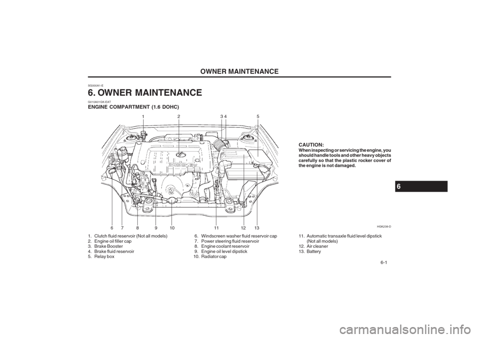
CAUTION: When inspecting or servicing the engine, you should handle tools and other heavy objects carefully so that the plastic rocker cover of the engine is not damaged.
SG000A1-E
6. OWNER MAINTENANCE
6
G010A01GK-EAT ENGINE COMPARTMENT (1.6 DOHC)
1. Clutch fluid reservoir (Not all models)
2. Engine oil filler cap
3. Brake Booster
4. Brake fluid reservoir
5. Relay box
6. Windscreen washer fluid reservoir cap
7. Power steering fluid reservoir
8. Engine coolant reservoir
9. Engine oil level dipstick
10. Radiator cap11. Automatic transaxle fluid level dipstick
(Not all models)
12. Air cleaner
13. Battery HGK238-D
1
23
45
6 7 8 9 10 11 12 13
Page 107 of 140
OWNER MAINTENANCE
6-2
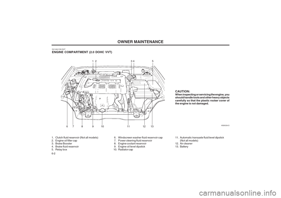
G010A01GK-EAT ENGINE COMPARTMENT (2.0 DOHC VVT) HGK059-D
CAUTION: When inspecting or servicing the engine, you should handle tools and other heavy objects carefully so that the plastic rocker cover of the engine is not damaged.
1. Clutch fluid reservoir (Not all models)
2. Engine oil filler cap
3. Brake Booster
4. Brake fluid reservoir
5. Relay box 6. Windscreen washer fluid reservoir cap
7. Power steering fluid reservoir
8. Engine coolant reservoir
9. Engine oil level dipstick
10. Radiator cap11. Automatic transaxle fluid level dipstick
(Not all models)
12. Air cleaner
13. Battery
12 3 45
6 7 8 9 10 11 12 13
Page 108 of 140
OWNER MAINTENANCE 6-3
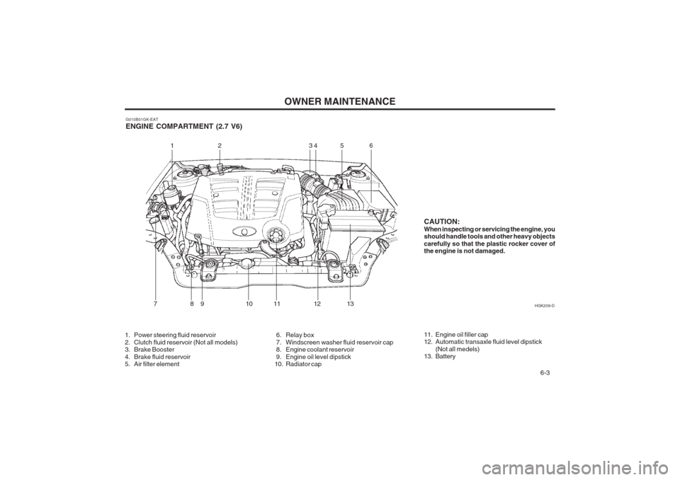
G010B01GK-EAT ENGINE COMPARTMENT (2.7 V6) HGK209-D
1. Power steering fluid reservoir
2. Clutch fluid reservoir (Not all models)
3. Brake Booster
4. Brake fluid reservoir
5. Air filter element 6. Relay box
7. Windscreen washer fluid reservoir cap
8. Engine coolant reservoir
9. Engine oil level dipstick
10. Radiator cap11. Engine oil filler cap
12. Automatic transaxle fluid level dipstick
(Not all medels)
13. Battery
12 3 45
7 8 9 10 11 126
13CAUTION: When inspecting or servicing the engine, you should handle tools and other heavy objects carefully so that the plastic rocker cover of the engine is not damaged.
Page 112 of 140
OWNER MAINTENANCE 6-7
ways wash thoroughly after any contact. Keep used oils out of reach of children. It is illegal to pollute drains, water courses and soil. Use only authorized waste collection facilities including civic amenity sites and garages for the disposal of used oil and oil filters. If in doubt, contact the local authority for dis- posal instructions. SG050A1-E ENGINE COOLANT CHECKING AND REPLACING WARNING: Do not remove the radiator cap when the engine is hot, since the system is pressurized and coolant may be ejected from the radiator resulting in scalding. SG050B1-E Coolant recommendations
Only ethylene glycol based coolant with a corro- sion inhibitor suited to aluminium alloy engine components should be used in the cooling sys- tem. No further additives or inhibitors should be used. The coolant specific gravity should be checked as prescribed in the maintenance sched- ule to ensure adequate frost and corrosion pro- tection. In addition, the engine coolant must be replaced at the specified interval since the corro- sion inhibitor properties deteriorate with time. It is important to note that whilst an increase in the concentration of anti freeze gives an increase in the level of frost protection, a solution which is in excess of 65% anti freeze will result in reduced frost protection and engine overheating. There- fore the recommended concentration of 50% should not be exceeded for general use. The use of methanol based anti freeze com- pounds may result in engine overheating and will invalidate the vehicle warranty. NOTE: It is imperative that vehicles fitted with an air conditioning system have a coolant concen- tration of the recommended strength at all times. The use of the air conditioning system when the cooling system is filled with water only will result in the heater matrix freezing and subsequently bursting.SG050C1-E Engine Coolant Level The engine coolant level may be observed through the side of the plastic coolant reservoir (expansion tank) when the engine is cold. If the level is below the "LOW" mark, add coolant of the correct concentration until the level is between the "LOW" and "Full" marks. If the level falls below the "LOW" mark on a regular basis despite being topped up, consult a Hyundai dealer. SG050D1-E To Change the Engine Coolant The engine coolant should be changed at those intervals specified in the vehicle maintenance schedule in Section 5. NOTE: Care should be taken to ensure that coolant is not allowed to spill onto the paintwork since the finish may become damaged. If coolant spillage occurs, the affected area should be rinsed thoroughly with water.
1. Park the vehicle on level ground and ensure
that the parking brake is firmly applied, and the engine allowed to cool. DO NOT ATTEMPT THIS OPERATION WHILST THE ENGINE IS HOT SINCE BURN-ING OR SCALDING MAY RESULT.
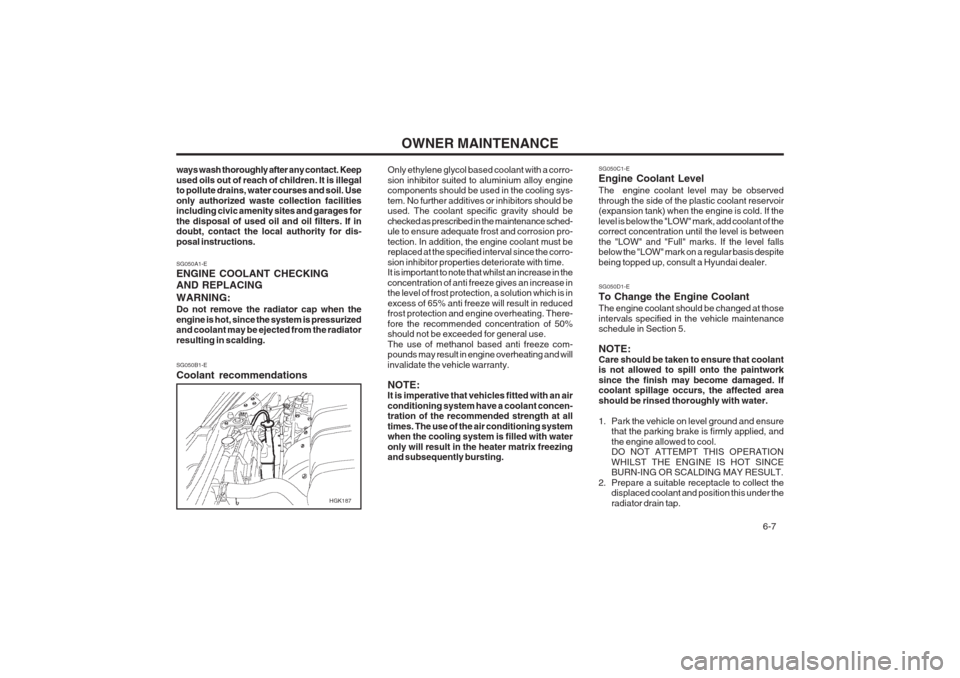
2. Prepare a suitable receptacle to collect the displaced coolant and position this under the radiator drain tap.
HGK187
Page 113 of 140
OWNER MAINTENANCE
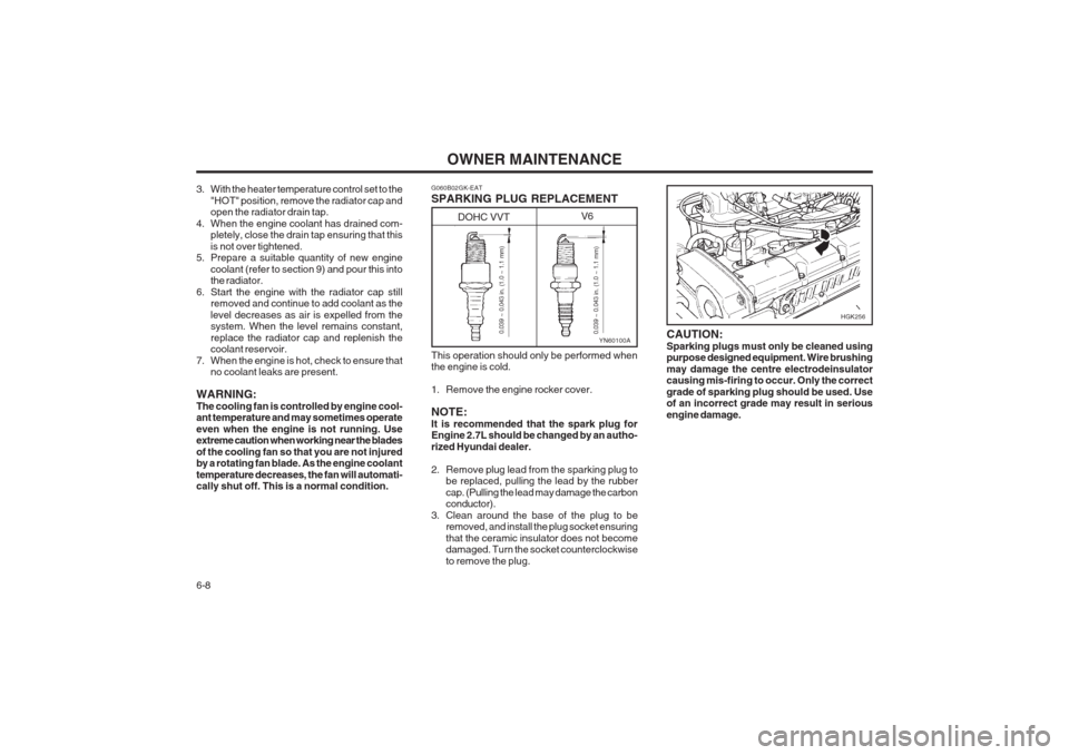
6-8 CAUTION: Sparking plugs must only be cleaned using purpose designed equipment. Wire brushing may damage the centre electrodeinsulator causing mis-firing to occur. Only the correct grade of sparking plug should be used. Use of an incorrect grade may result in serious engine damage.
3. With the heater temperature control set to the
"HOT" position, remove the radiator cap and open the radiator drain tap.
4. When the engine coolant has drained com- pletely, close the drain tap ensuring that this is not over tightened.
5. Prepare a suitable quantity of new engine
coolant (refer to section 9) and pour this into the radiator.
6. Start the engine with the radiator cap still removed and continue to add coolant as the level decreases as air is expelled from the system. When the level remains constant, replace the radiator cap and replenish the coolant reservoir.
7. When the engine is hot, check to ensure that no coolant leaks are present.
WARNING: The cooling fan is controlled by engine cool- ant temperature and may sometimes operate even when the engine is not running. Use extreme caution when working near the blades of the cooling fan so that you are not injured by a rotating fan blade. As the engine coolant temperature decreases, the fan will automati- cally shut off. This is a normal condition. G060B02GK-EAT SPARKING PLUG REPLACEMENT This operation should only be performed when the engine is cold.
1. Remove the engine rocker cover.NOTE: It is recommended that the spark plug for Engine 2.7L should be changed by an autho- rized Hyundai dealer.
2. Remove plug lead from the sparking plug to
be replaced, pulling the lead by the rubber cap. (Pulling the lead may damage the carbon conductor).
3. Clean around the base of the plug to be removed, and install the plug socket ensuring that the ceramic insulator does not become damaged. Turn the socket counterclockwise to remove the plug.
YN60100A0.039 ~ 0.043 in. (1.0 ~ 1.1 mm)
0.039 ~ 0.043 in. (1.0 ~ 1.1 mm)
DOHC VVT V6
HGK256
Page 127 of 140
OWNER MAINTENANCE
6-22
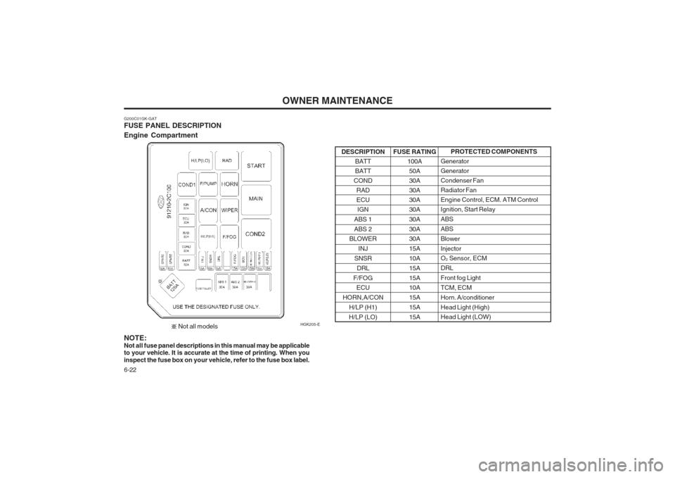
G200C01GK-GAT FUSE PANEL DESCRIPTION Engine Compartment HGK205-EPROTECTED COMPONENTS
GeneratorGeneratorCondenser FanRadiator FanEngine Control, ECM. ATM ControlIgnition, Start Relay ABSABSBlowerInjector O 2 Sensor, ECM
DRL Front fog LightTCM, ECMHorn. A/conditionerHead Light (High) Head Light (LOW)
FUSE RATING
100A50A30A30A30A30A 30A30A 30A 15A10A15A15A 10A 15A15A15A
DESCRIPTION
BATT BATT
COND RADECUIGN
ABS 1 ABS 2
BLOWER
INJ
SNSR DRL
F/FOG ECU
HORN,A/CON H/LP (H1)
H/LP (LO)
NOTE:
Not all fuse panel descriptions in this manual may be applicable
to your vehicle. It is accurate at the time of printing. When youinspect the fuse box on you r vehicle, refer to the fuse box label.
Not all models