air condition Hyundai Coupe 2003 Repair Manual
[x] Cancel search | Manufacturer: HYUNDAI, Model Year: 2003, Model line: Coupe, Model: Hyundai Coupe 2003Pages: 310, PDF Size: 2.87 MB
Page 289 of 310

OWNER MAINTENANCE
6-14 SG140B1-E Compressor Drive Belt The air conditioning compressor drive belt should be checked to ensure freedom from damage or excessive wear and correct tension. The belt tension is correct when the belt deflects by about0.3 inches (8 mm) when a force of 98 N is appliedto the belt halfway between the compressor andcrankshaft pulleys. Adjustment of the belt shouldbe entrusted to a Hyundai dealer.
SG140C2-E Checking the Refrigerant
1. Start the engine and run at idle for several
minutes with the refrigeration system running at the coldest setting.
2. If the air coming out of the in-dash vents is not cold, have the air conditioning system in-spected by your Hyundai dealer.
CAUTION:Running the air conditioning system for ex-tended periods of time with a low refrigerantlevel may damage the compressor. A/C
CRANK PULLEY
TENSION PULLEY 0.315 in. (8mm)
G140D01GK
V6
DOHC
Auto tensioner
Eng.pulley COMP
SG140D1-E Off Season Maintenance The air conditioning must be run for ten minutes or so weekly during periods when the systemwould not normally be used to ensure that thecompressor and seals are lubricated. If this pre-caution is not observed the compressor sealsmay become stuck to the compressor shaft anddamaged when the system is next used resultingin a loss of refrigerant and damage to the com-pressor. B760B01GK-GAT Replacement of air conditioner filter:
HGK250-D
1. Remove the mounting screws on the down- side of the glove box.
2. Open the glove box and remove the mounting screws on the upside of the glove box.
HGK251-D
Page 293 of 310
OWNER MAINTENANCE
6-18 NOTE: Grinding noise from power steering pumpmay be heard immediately after the engine isstarted in extremely cold condition (below-20°C). In this case, if the noise stops duringwarm up, there is no abnormal function in thesystem. This is due to a power steering fluidcharacteristic in extremely cold conditions. FLUID RECOMMENDATION
Only automatic transaxle fluid meeting the speci-
fication of PSF-3 or Dexron 2 oil should be used in the power steering system.
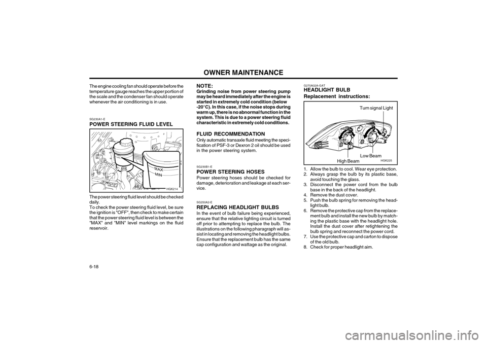
SG230A1-E POWER STEERING FLUID LEVEL The power steering fluid level should be checked daily.To check the power steering fluid level, be surethe ignition is "OFF", then check to make certainthat the power steering fluid level is between the"MAX" and "MIN" level markings on the fluidreservoir.
SG250A2-E REPLACING HEADLIGHT BULBSIn the event of bulb failure being experienced, ensure that the relative lighting circuit is turnedoff prior to attempting to replace the bulb. Theillustrations on the following pharagraph will as-sist in locating and removing the headlight bulbs.Ensure that the replacement bulb has the samecap configuration and wattage as the original.
SG230B1-E POWER STEERING HOSESPower steering hoses should be checked for damage, deterioration and leakage at each ser-vice.
The engine cooling fan should operate before thetemperature gauge reaches the upper portion ofthe scale and the condenser fan should operatewhenever the air conditioning is in use.
HGK214 G270A02A-GAT HEADLIGHT BULB Replacement instructions:
HGK225
1. Allow the bulb to cool. Wear eye protection.
2. Always grasp the bulb by its plastic base, avoid touching the glass.
3. Disconnect the power cord from the bulb base in the back of the headlight.
4. Remove the dust cover.
5. Push the bulb spring for removing the head- light bulb.
6. Remove the protective cap from the replace- ment bulb and install the new bulb by match-ing the plastic base with the headlight hole.Install the dust cover after retightening thebulb spring and reconnect the power cord.
7. Use the protective cap and carton to dispose of the old bulb.
8. Check for proper headlight aim.High Beam Low Beam
Turn signal Light
Page 298 of 310
OWNER MAINTENANCE 6-23
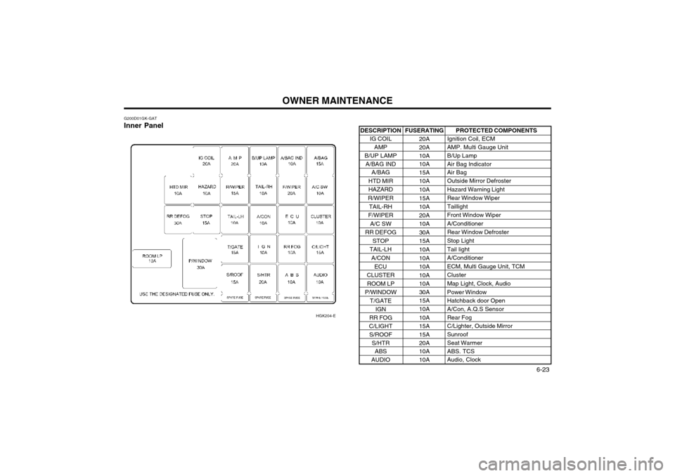
DESCRIPTION
IG COIL
AMP
B/UP LAMP
A/BAG IND A/BAG
HTD MIR
HAZARD
R/WIPER
TAIL-RH
F/WIPER A/C SW
RR DEFOG STOP
TAIL-LH
A/CON ECU
CLUSTER
ROOM LP
P/WINDOW T/GATE IGN
RR FOG
C/LIGHT S/ROOF
S/HTR ABS
AUDIO
G200D01GK-GAT Inner Panel
HGK204-E
PROTECTED COMPONENTS
Ignition Coil, ECM
AMP. Multi Gauge Unit B/Up Lamp Air Bag Indicator Air Bag Outside Mirror Defroster Hazard Warning LightRear Window WiperTaillightFront Window WiperA/ConditionerRear Window Defroster Stop Light Tail lightA/ConditionerECM, Multi Gauge Unit, TCMClusterMap Light, Clock, Audio Power Window Hatchback door OpenA/Con, A.Q.S Sensor Rear Fog C/Lighter, Outside MirrorSunroof Seat Warmer ABS. TCS Audio, Clock
FUSERATING
20A20A 10A 10A 15A10A 10A 15A10A20A10A30A15A 10A 10A10A10A 10A 30A 15A10A 10A 15A15A20A 10A 10A
Page 299 of 310
EMISSION CONTROL SYSTEM 7-1
SH010A1-E EMISSION CONTROL SYSTEMS (Not all models) Depending upon the market for which the vehicleis destined, the emission control system willcomprise one or more of the following emissioncontrol devices. (1) Crankcase emission control system (2) Evaporative emission control system(3) Exhaust emission control system In order that the proper functioning of the emis- sion control systems may be ensured, it isrecommended that the vehicle is inspected andmaintained by an authorized Hyundai dealer inaccordance with the maintenance schedule inthis manual.
SH000A1-E
7. EMISSION
CONTROL SYSTEM
SH010B1-E
1. CRANKCASE EMISSION CONTROL SYSTEM
The positive crankcase ventilation system is employed to prevent air pollution caused byblow-by gases being emitted from the crankcase by introducing fresh air to the crankcase throughthe air cleaner where this mixes with blow-bygases and then passes through the PCV valveinto the intake manifold from where it subse-quently enters the combustion chamber and isburned.
SH010D1-E
3. EXHAUST EMISSION CONTROL SYSTEM The exhaust emission control system is a highlyeffective system which controls exhaust emis-sion while maintaining good vehicle performance.
SH010C1-E
2. EVAPORATIVE EMISSION CONTROL SYSTEM
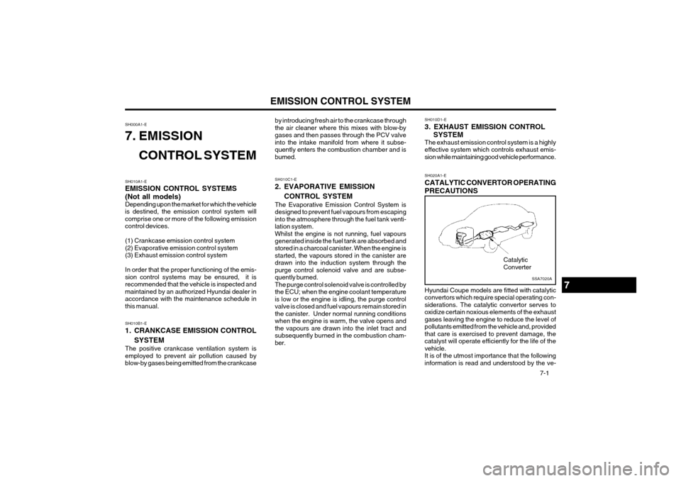
The Evaporative Emission Control System is designed to prevent fuel vapours from escapinginto the atmosphere through the fuel tank venti-lation system.Whilst the engine is not running, fuel vapours generated inside the fuel tank are absorbed and stored in a charcoal canister. When the engine isstarted, the vapours stored in the canister aredrawn into the induction system through thepurge control solenoid valve and are subse-quently burned.The purge control solenoid valve is controlled bythe ECU; when the engine coolant temperatureis low or the engine is idling, the purge controlvalve is closed and fuel vapours remain stored inthe canister. Under normal running conditionswhen the engine is warm, the valve opens andthe vapours are drawn into the inlet tract andsubsequently burned in the combustion cham-ber. SH020A1-E CATALYTIC CONVERTOR OPERATING PRECAUTIONS Hyundai Coupe models are fitted with catalytic convertors which require special operating con-siderations. The catalytic convertor serves tooxidize certain noxious elements of the exhaustgases leaving the engine to reduce the level ofpollutants emitted from the vehicle and, providedthat care is exercised to prevent damage, thecatalyst will operate efficiently for the life of thevehicle.It is of the utmost importance that the followinginformation is read and understood by the ve-
7
Catalytic Converter
SSA7020A
Page 307 of 310
INDEX10-1
C CARE OF CAS
SETTE TAPE ........................................................... 1-65
CARE OF DISC ................................................................................ 1-65
CARE OF SEAT BELTS .................................................................. 1-12
CATALYTIC CONVERTOR OPERATING PRECAUTIONS .......7-1~7-2
CENTRAL DOOR LOCK .................................................................... 1-4
CHANGING A FLAT TYPE ................................................................ 3-3
CHECKING THE CLUTCH FLUID ................................................... 6-13
CHILD RESTRAINT SYSTEM ......................................................... 1-14
CIGAR LIGHTER .............................................................................. 1-37
CLUTCH PEDAL FREEPLAY .......................................................... 6-15
COMBINATION IGNITION SWITCH AND STEERING LOCK .......... 2-2
CRUISE CONTROL ......................................................................... 1-49
D DAILY OPERATING CHECKS ........................................................... 6-4
DEFROSTING/DEFOGGING ........................................................... 1-55
DIGITAL CLOCK .............................................................................. 1-37
DOOR LOCKS .................................................................................... 1-2 DOOR WINDOWS .............................................................................. 1-6
DRINK HOLDER .............................................................................. 1-38
DRIVE BELTS .................................................................................. 6-16
DRIVING FOR ECONOMY .............................................................. 2-10
JK000A2-EAT 10. INDEX
A AIR BAG ........................................................................................... 1-19
AIR CONDITIONING SWITCH ......................................................... 1-56
AIR CONDITIONING SYSTEM MAINTENANCE ............................6-13
AIR CLEANER ELEMENT REPLACEMENT ..................................... 6-9
AIR CONDITIONER FILTER ............................................................ 1-62
ANTENNA ......................................................................................... 1-67
ANTI-LOCK BRAKE SYSTEM ........................................................... 2-8
AUTOMATIC TRANSMISSION FLUID ............................................. 6-11
AUTOMATIC TRANSMISSION .......................................................... 2-5
BBATTERY MAINTENANCE .............................................................. 6-17
BEFORE FOLDING THE REAR SEATS ......................................... 1-10
BEFORE STARTING THE ENGINE .................................................. 2-2
BONNET RELEASE ......................................................................... 1-45
BRAKE PEDAL FREEPLAY ............................................................. 6-16
BRAKE SYSTEM CHECKING ......................................................... 6-12
10