low beam Hyundai Coupe 2004 User Guide
[x] Cancel search | Manufacturer: HYUNDAI, Model Year: 2004, Model line: Coupe, Model: Hyundai Coupe 2004Pages: 389, PDF Size: 10.22 MB
Page 219 of 389

1
CONTROLS AND EQUIPMENT
39
1. Speedometer
2. Turn Signal Indicator Light
3. Odometer/Trip Odometer
4. Automatic Transaxle Position Indicator Light (Not all models)
5. Coolant Temperature Gauge
6. Trip Computer
7. Fuel Gauge
8. Tachometer
9. Electronic Stability Program (ESP) Indicator Light (Not all models)
10.Immobiliser Warning Light
11.Odometer/Trip Odometer Reset Knob 12.Charging System Warning Light
13.SRS (Airbag) Warning Light
14.Seat Belt Warning Light
15.High Beam Indicator Light
16.Oil Pressure Warning Light
17.Malfuction Indicator Light (Not all models)
18.Low Fuel Warning Light
19.Parking Brake/Brake Fluide Level Warning Light
20.Trip Computer Reset Knob21.CRUISE Indicator Light (Not all models)
22.CRUISE SET Indicator Light (Not all models)
23.Hatchback door Open Warning Light
24.Door Ajar Warning Light
25.Anti-Lock Brake Warning Light (Not all models)
Page 220 of 389
1CONTROLS AND EQUIPMENT
40
!
!
WARNING AND INDICATOR LIGHTS
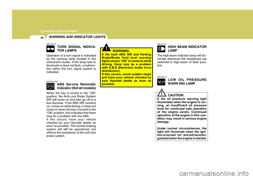
SB210K1-ELOW OIL PRESSURE WARN ING LAMP
SB210G1-ETURN SIGNAL INDICA- TOR LAMPS
Operation of a turn signal is indicated by the warning lamp located in theinstrument cluster. If the lamp fails to illuminate or does not flash, a malfunc- tion within the turn signal system isindicated. 260P02Y-EAT ABS Service Reminder Indicator (Not all models)
When the key is turned to the "ON" position, the Anti-Lock Brake System SRI will come on and then go off in afew seconds. If the ABS SRI remains on, comes on while driving, or does not come on when the key is turned to the"ON" position, this indicates that there may be a problem with the ABS. If this occurs, have your vehiclechecked by your Hyundai dealer as soon as possible. The normal braking system will still be operational, butwithout the assistance of the anti-lock brake system. WARNING:
If the both ABS SRI and ParkingBrake/Brake fluid level warning lights remain "ON" or come on whiledriving, there may be a problem with E.B.D (Electronic brake force distribution).If this occurs, avoid sudden stops and have your vehicle checked by your Hyundai dealer as soon aspossible.SB210J1-E HIGH BEAM INDICATOR LAMP
The high beam indicator lamp will illu- minate whenever the headlamps areswitched to high beam of flash posi- tion.
CAUTION:
If the oil pressure warning light illuminates when the engine is run- ning, an insufficient oil pressure level for continued safe operationof the engine exists. Continued operation of the engine in this con- dition may result in serious enginedamage. Under normal circumstances, the light will illuminate when the igni- tion is turned "on" and will be extin- guished when the engine is started.
Page 231 of 389
1
CONTROLS AND EQUIPMENT
51
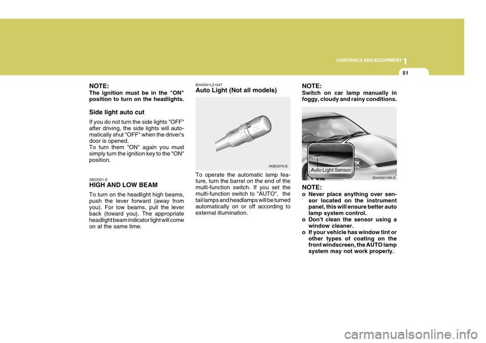
NOTE: The ignition must be in the "ON" position to turn on the headlights. Side light auto cut If you do not turn the side lights "OFF" after driving, the side lights will auto-matically shut "OFF" when the driver's door is opened. To turn them "ON" again you mustsimply turn the ignition key to the "ON" position. SB220D1-E HIGH AND LOW BEAM To turn on the headlight high beams, push the lever forward (away fromyou). For low beams, pull the lever back (toward you). The appropriate headlight beam indicator light will comeon at the same time. B340G01LZ-GAT Auto Light (Not all models) To operate the automatic lamp fea- ture, turn the barrel on the end of the multi-function switch. If you set themulti-function switch to "AUTO", the tail lamps and headlamps will be turned automatically on or off according toexternal illumination.
HGK2075-ENOTE: Switch on car lamp manually in foggy, cloudy and rainy conditions. NOTE:
o Never place anything over sen-
sor located on the instrument panel, this will ensure better auto lamp system control.
o Don't clean the sensor using a window cleaner.
o If your vehicle has window tint or other types of coating on the front windscreen, the AUTO lamp system may not work properly. B340G01GK-E
Auto Light Sensor
Page 238 of 389
1CONTROLS AND EQUIPMENT
58
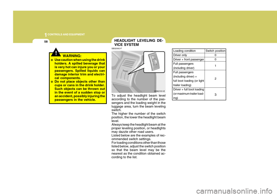
Switch position
0 0 1 2
3Loading condition Driver only Driver + front passenger Full passengers(including driver) Full passengers (including driver) +full boot loading (or light trailer loading) Driver + full boot loading(or maximum trailer load-ing)
!WARNING:
o Use caution when using the drink holders. A spilled beverage that is very hot can injure you or your passengers. Spilled liquids can damage interior trim and electri-cal components.
o Do not place objects other than
cups or cans in the drink holder.Such objects can be thrown out in the event of a sudden stop or an accident, possibly injuring thepassengers in the vehicle.
HEADLIGHT LEVELING DE- VICE SYSTEM
SB320A2-F To adjust the headlight beam level according to the number of the pas- sengers and the loading weight in theluggage area, turn the beam leveling switch. The higher the number of the switchposition, the lower the headlight beam level. Always keep the headlight beam at theproper leveling position, or headlights may dazzle other road users. Listed below are the examples of rec-ommended switch settings. For loading conditions other than those listed below, adjust the switch positionso that the beam level may be the nearest as the condition obtained ac- cording to the list. HGK2151-E
Page 357 of 389
6
OWNER MAINTENANCE
31
HGK5011
G230A03A-EAT
Power Steering Fluid Level Fluid Recommendation
Only automatic transaxle fluid meet-
ing the specification of PSF-3 or ATF DEXRON 2 should be used in thepower steering system.
The power steering fluid level should
be checked regularly.
To check the power steering fluid
level, be sure the ignition is "OFF",then check to make certain that thepower steering fluid level is between the "MAX" and "MIN" level markings on the fluid reservoir.
NOTE: Do not check whilst the engine is
running. Do not start when power steering fluid reservoir is empty.High Beam
G290A01GK
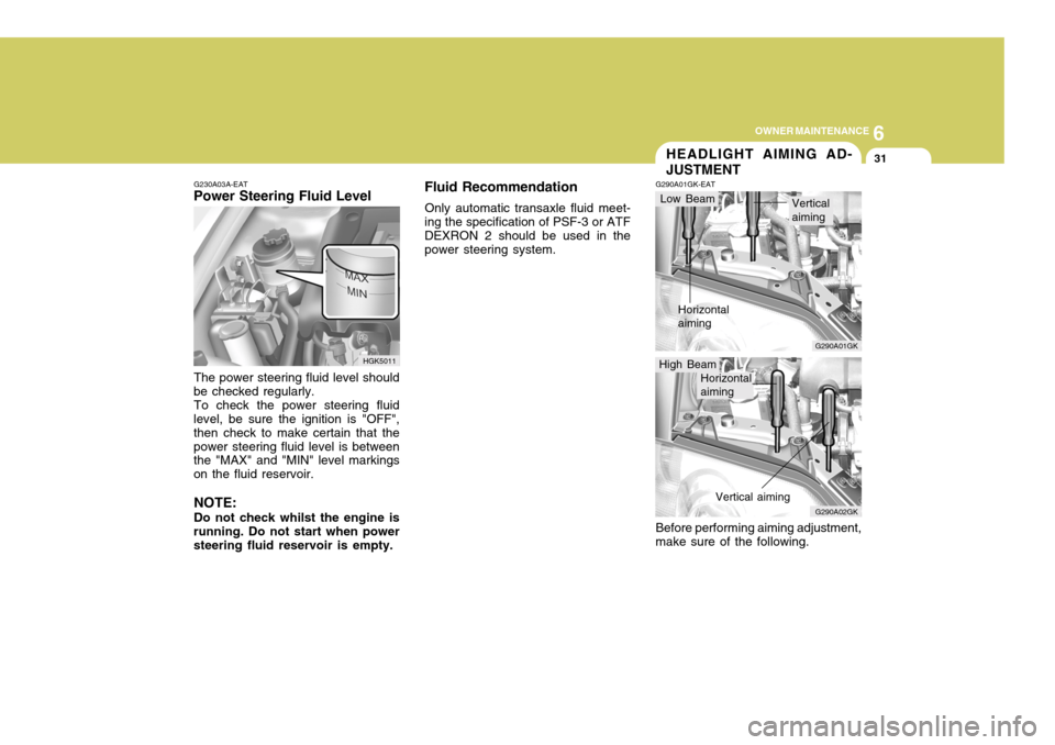
G290A01GK-EAT HEADLIGHT AIMING AD- JUSTMENT
Before performing aiming adjustment, make sure of the following.
G290A02GK
Low Beam
Horizontal aiming Verticalaiming
Horizontal aiming Vertical aiming
Page 358 of 389
6OWNER MAINTENANCE
32
G290B01GK-EAT
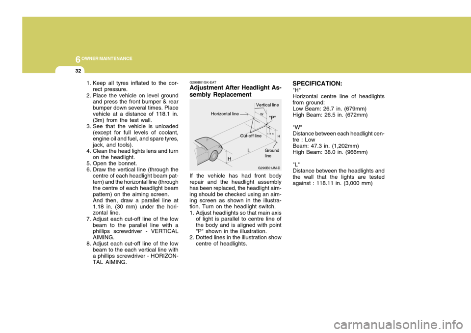
Adjustment After Headlight As- sembly Replacement
If the vehicle has had front body
repair and the headlight assembly has been replaced, the headlight aim- ing should be checked using an aim-ing screen as shown in the illustra- tion. Turn on the headlight switch.
1. Adjust headlights so that main axis of light is parallel to centre line of the body and is aligned with point"P" shown in the illustration.
2. Dotted lines in the illustration show centre of headlights. SPECIFICATION:
"H" Horizontal centre line of headlights from ground: Low Beam: 26.7 in. (679mm) High Beam: 26.5 in. (672mm) "W" Distance between each headlight cen- tre : Low Beam: 47.3 in. (1,202mm) High Beam: 38.0 in. (966mm) "L" Distance between the headlights and the wall that the lights are tested against : 118.11 in. (3,000 mm)
1. Keep all tyres inflated to the cor-
rect pressure.
2. Place the vehicle on level ground and press the front bumper & rearbumper down several times. Placevehicle at a distance of 118.1 in. (3m) from the test wall.
3. See that the vehicle is unloaded (except for full levels of coolant, engine oil and fuel, and spare tyres,jack, and tools).
4. Clean the head lights lens and turn on the headlight.
5. Open the bonnet.
6. Draw the vertical line (through the centre of each headlight beam pat- tern) and the horizontal line (through the centre of each headlight beampattern) on the aiming screen.And then, draw a parallel line at1.18 in. (30 mm) under the hori- zontal line.
7. Adjust each cut-off line of the low beam to the parallel line with aphillips screwdriver - VERTICAL AIMING.
8. Adjust each cut-off line of the low beam to the each vertical line witha phillips screwdriver - HORIZON- TAL AIMING. L
G290B01JM-D
W
H
H Cut-off line"P"
Vertical lineHorizontal line
Ground line
1.18 in.