glove box Hyundai Coupe 2005 User Guide
[x] Cancel search | Manufacturer: HYUNDAI, Model Year: 2005, Model line: Coupe, Model: Hyundai Coupe 2005Pages: 478, PDF Size: 13.44 MB
Page 220 of 478

6 DO-IT-YOURSELF MAINTENANCE
22
!
CHANGING THE AIR CONDI- TIONER FILTER
G145A02GK-GAT (In front of blower unit) (If installed) The air conditioner filter is located in front of the blower unit behind the glove box.It helps to decrease the amount ofpollutants entering the car.
2. Open the glove box and removethe mounting screws on the upside of the glove box.
1. Remove the mounting screws on the downside of the glove box. 4. Replace the air conditioner filter
with a new one.
5. Installation is the reverse order of disassembly.
CAUTION:
Be sure to install the air condi-
tioner filter in the direction of thearrow sign. Otherwise, it may cause noise or deterioration.
HGK2111
HGK2112
HGK2114
HGK2115
3. Remove the filter cover.
Page 235 of 478

6
DO-IT-YOURSELF MAINTENANCE
37
G270G01GK-AAT
Map Light
1. Remove the cover with a flat-blade screwdriver.
2. Replace with a new bulb.
HGK5047
HGK5048HGK2112
2. Open the glove box and remove the mounting screws on the upside of the glove box.
G270H01GK-GAT
Glove Box Illuminated Light
1. Remove the mounting screws on
the downside of the glove box. HGK2111
3. Remove the glove box by pulling
strongly.
CAUTION:
Be careful not to damage the glove box when pulling the glove box.
!
HGK5052
Page 236 of 478

6 DO-IT-YOURSELF MAINTENANCE
38
HTB284
HGK5053
Clip Power Cord
4. Disconnect the power cord.
5. Remove the glove box illuminated light by pushing the clip.
6. Replace with a new bulb.
Page 241 of 478
6
DO-IT-YOURSELF MAINTENANCE
43
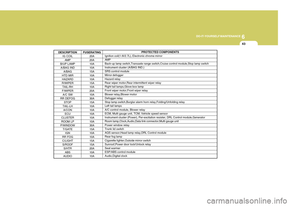
DESCRIPTION IG COIL
AMP
B/UP LAMP
A/BAG IND A/BAG
HTD MIR HAZARD
R/WIPER TAIL-RH
F/WIPER A/C SW
RR DEFOG STOP
TAIL-LH A/CON
ECU
CLUSTER
ROOM LP
P/WINDOW
T/GATE IGN
RR FOG C/LIGHT
S/ROOF S/HTR
ABS
AUDIO
PROTECTED COMPONENTS
Ignition coil(1.6l/2.7L), Electronic chrome mirror AMP Back-up lamp switch,Transaxle range switch,Cruise control module,Stop lamp switch Instrument cluster (A/BAG IND.) SRS control module Mirror defogger Hazard relay Rear wiper motor,Rear intermittent wiper relay Right tail lamps,Glove box lamp Front wiper motor,Front wiper relay Blower relay,Blower motor Defogger relay Stop lamp switch,Burglar alarm horn relay,Folding/Unfolding relay Left tail lamps A/C control module, Blower relay ECM, Multi gauge unit, TCM, Vehicle speed sensor Instrument cluster (Power), Per-excitation resister, DRL Control module,Generator Room lamp,Clock,Audio,Data link connector,Multi gauge unit Power window relay Trunk lid switch AQS sensor,Head lamp relay,DRL Control module Rear fog lamp Cigarette lighter,Outside mirror switch Sunroof,Power door lock/Unlock relay Seat warmer ESP/ABS control module Audio,Digital clock
FUSERATING
20A20A 10A 10A 15A 10A 10A 15A 10A 20A 10A 30A 15A 10A 10A 10A 10A 10A 30A 15A 10A 10A 15A 15A 20A 10A 10A
Page 257 of 478
10
INDEX
3
D Defrosting/Defogging ................................................... 1-82
Door
Central door lock ...................................................... 1-8
Door locks ................................................................ 1-7Locking and unlocking front door with a key ............ 1-7
Drink Holder ................................................................ 1-59
Drive Belts .................................................................. 6-24
Driving
Economical driving .................................................. 2-16
Smooth corneri ng ..................................................... 2-17
Winter driving ........................................................... 2-18
E
Emissions Control Systems ........................................ 7-2 Engine
Before starting the engine ........................................ 2-3
Changing the oil and filter ......................................... 6-8 Compartment (1.6L, 2.0L, 2.7L) ................................ 6-2
Coolant .................................................................... 6-10
Coolant temperature gauge ......................................1-46
If the engine overheats ............................................. 3-4
Number ..................................................................... 8-2
Oil ............................................................................. 6-6Oil consumption ........................................................ 6-7
Starting ..................................................................... 2-4
Engine Exhaust Can Be Dangerous ............................ 2-2 FFog Light
.................................................................... 1-56
Front Seats
Adjustable front seats .............................................. 1-13
Adjustable headrests ............................................... 1-14
Adjusting seat forward and rearward ........................1-13
Adjusting seatback angle .. ......................................1-14
Lumbar support control ............................................ 1-15
Seat cushion height adjustment .............................. 1-16
Seat warmer ............................................................ 1-16
Fuel
Capacity ................................................................... 9-2
Gauge ...................................................................... 1-46
Recommendations .................................................... 1-2
Fuel Filler Lid
Remote release ....................................................... 1-68
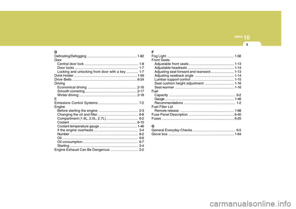
Fuse Panel Description .............................................. 6-40
Fuses ......................................................................... 6-25
G
General Everyday Checks ..... ...................................... 6-5
Glove box ................................................................... 1-64
Page 270 of 478
CAUTION:
When installing a container of liquid air freshener inside the vehicle, do not place it near the instrument cluster nor on the instrument panel surface. If there is any leakage from the air freshener onto these areas (Instrument cluster, instrument panel or air ventilator), it may damage these parts. If the liquid from the air freshener does leak onto these areas, wash themwith water immediately.!
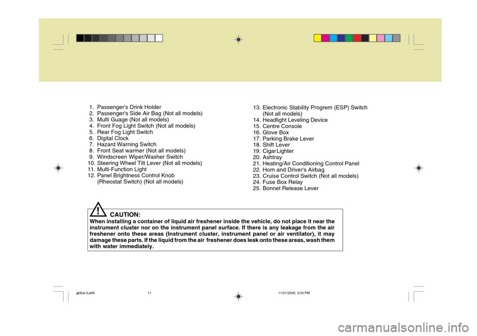
1. Passenger's Drink Holder
2. Passenger's Side Air Bag (Not all models)
3. Multi Guage (Not all models)
4. Front Fog Light Switch (Not all models)
5. Rear Fog Light Switch
6. Digital Clock
7. Hazard Warning Switch
8. Front Seat warmer (Not all models)
9. Windscreen Wiper/Washer Switch
10. Steering Wheel Tilt Lever (Not all models)
11. Multi-Function Light
12. Panel Brightness Control Knob
(Rheostat Switch) (Not all models) 13. Electronic Stability Progrem (ESP) Switch
(Not all models)
14. Headlight Leveling Device
15. Centre Console
16. Glove Box
17. Parking Brake Lever
18. Shift Lever
19. Cigar Lighter
20. Ashtray
21. Heating/Air Conditioning Control Panel
22. Horn and Driver's Airbag
23. Cruise Control Switch (Not all models)
24. Fuse Box Relay
25. Bonnet Release Lever
gkfluk-0.p65 11/21/2005, 3:03 PM
11
Page 301 of 478
1CONTROLS AND EQUIPMENT
30
o Improper handling of the pre-
tensioner seat belt assemblies, and failure to heed the warnings to not strike, modify, inspect, re-place, service or repair the pre- tensioner seat belt assemblies may lead to improper operationor inadvertent activation and se- rious injury.
o Always wear seat belts when driv- ing or riding in a motor vehicle.
SUPPLEMENTAL RESTRAINT (AIRBAG) SYSTEM (SRS)
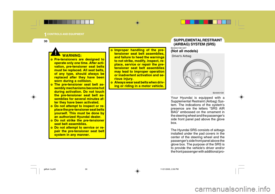
B240A01GK-GAT (Not all models) Your Hyundai is equipped with a Supplemental Restraint (Airbag) Sys- tem. The indications of the system'spresence are the letters "SRS AIR BAG" embossed on the ornament in the steering wheel and the passenger'sside front panel pad above the glove box. The Hyundai SRS consists of airbags installed under the pad covers in the center of the steering wheel and thepassenger's side front panel above the glove box. The purpose of the SRS is to provide the vehicle's driver and/orthe front passenger with additional pro- Driver's Airbag
B240A01GK
!WARNING:
o Pre-tensioners are designed to operate only one time. After acti- vation, pre-tensioner seat belts must be replaced. All seat belts, of any type, should always bereplaced after they have been worn during a collision.
o The pre-tensioner seat belt as- sembly mechanisms become hotduring activation. Do not touch the pre-tensioner seat belt as-semblies for several minutes af- ter they have been activated.
o Do not attempt to inspect or re- place the pre-tensioner seat beltsyourself. This must be done by an authorized Hyundai dealer.
o Do not strike the pre-tensioner seat belt assemblies.
o Do not attempt to service or re- pair the pre-tensioner seat belt system in any manner.
gkfluk-1a.p65 11/21/2005, 2:56 PM
30
Page 302 of 478
1
CONTROLS AND EQUIPMENT
31
!
tection than that offered by the seat belt system alone, in case of a frontalimpact of sufficient severity. NOTE: Be sure to read information about the SRS on the labels provided onthe front side of the sun visor and in the glove box.
WARNING:
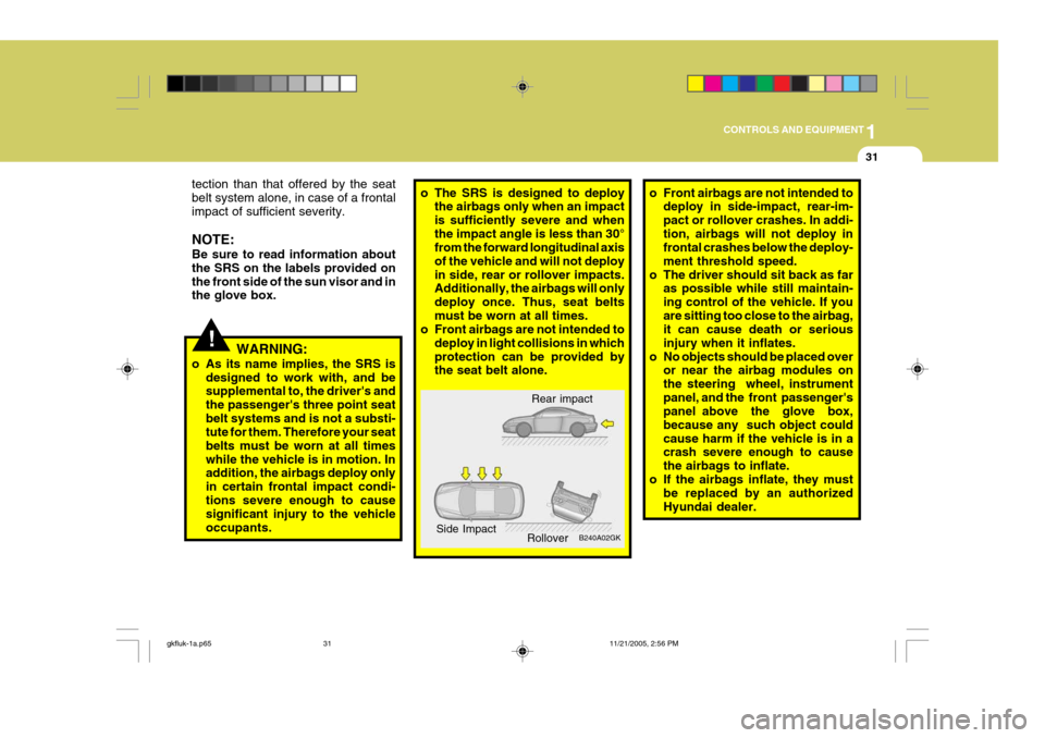
o As its name implies, the SRS is designed to work with, and besupplemental to, the driver's and the passenger's three point seatbelt systems and is not a substi- tute for them. Therefore your seat belts must be worn at all timeswhile the vehicle is in motion. In addition, the airbags deploy only in certain frontal impact condi-tions severe enough to cause significant injury to the vehicle occupants.o The SRS is designed to deploy the airbags only when an impact is sufficiently severe and whenthe impact angle is less than 30° from the forward longitudinal axis of the vehicle and will not deployin side, rear or rollover impacts. Additionally, the airbags will only deploy once. Thus, seat beltsmust be worn at all times.
o Front airbags are not intended to
deploy in light collisions in whichprotection can be provided by the seat belt alone. o Front airbags are not intended to
deploy in side-impact, rear-im- pact or rollover crashes. In addi-tion, airbags will not deploy in frontal crashes below the deploy- ment threshold speed.
o The driver should sit back as far as possible while still maintain-ing control of the vehicle. If youare sitting too close to the airbag, it can cause death or serious injury when it inflates.
o No objects should be placed over or near the airbag modules onthe steering wheel, instrumentpanel, and the front passenger's panel above the glove box, because any such object couldcause harm if the vehicle is in a crash severe enough to cause the airbags to inflate.
o If the airbags inflate, they must be replaced by an authorizedHyundai dealer.
Rear impact
B240A02GK
Side Impact
Rollover
gkfluk-1a.p65 11/21/2005, 2:56 PM
31
Page 304 of 478

1
CONTROLS AND EQUIPMENT
33
The SRS service reminder indicator (SRI) on the instrument panel will comeon for approximately 6 seconds after the ignition key is turned to the "ON" position or after the engine is started,after which the SRI should go out. The airbag modules are located both in the centre of the steering wheel and in the front passenger's panel above the glove box. When the SRSCM detects aconsiderable impact to the front of the vehicle, it will automatically deploy the airbags. B240B02L-R Passenger's Airbag
Upon deployment, tear seams moldeddirectly into the pad covers will sepa-rate under pressure from the expan- sion of the airbags. Further opening of the covers then allows full inflation ofthe airbags. A fully inflated airbag in combination with a properly worn seat belt slows the driver's or the passenger's forward motion, thus reducing the risk of headand chest injury. After complete inflation, the airbag immediately starts deflating, enabling the driver to maintain forward visibility. B240B03L-R
B240B01GK-E
!
CAUTION:
Do not install or place any accesso- ries (drink holder, cassette holder, sticker, etc) on the front passenger'spanel above the glove box in the vehicle with passenger's side air bag. Such objects may becomedangerous projectiles and cause injury if the passenger's side air bag inflates.
gkfluk-1a.p65 11/21/2005, 2:56 PM
33
Page 331 of 478

1CONTROLS AND EQUIPMENT
60
2. Insert the hexagonal head wrenchprovided with the vehicle into the socket. This wrench can be found in the vehicle's boot or glove box.
3. Push and turn the wrench clockwise
to open or counterclockwise to closethe sunroof.
HGK2025
B460D03GK-AAT Manual Operation of Sunroof If the sunroof does not electrically op- erate:
1. Remove the cap located in the rear
roof panel by using a coin or driver.
HGK2024
B460C01S-GAT Tilting the Sunroof System The sunroof can be tilted by pushing the "UP" button with the sunroof closed. Release the button when the sunroofreaches the desired position. To close the sunroof, press the "DOWN" but- ton. NOTE: After washing the car or after there is rain, be sure to wipe off any waterthat is on the sunroof before oper- ating it.
HGK2023
gkfluk-1a.p65 11/21/2005, 2:56 PM
60