instrument cluster Hyundai Coupe 2006 User Guide
[x] Cancel search | Manufacturer: HYUNDAI, Model Year: 2006, Model line: Coupe, Model: Hyundai Coupe 2006Pages: 483, PDF Size: 12.73 MB
Page 255 of 483

10
INDEX
3
Driving Economical driving .................................................. 2-16
Smooth corneri ng ..................................................... 2-17
Winter driving ........................................................... 2-17
E Electronic Stability Program (ESP) ............................2-13
Emissions Control Systems ........................................ 7-2 Engine Before starting the engine ........................................ 2-3
Changing the oil and filter ......................................... 6-6Compartment (1.6L, 2.0L, 2.7L) ................................ 6-2
Coolant ..................................................................... 6-9
Coolant temperature gauge ......................................1-50
If the engine overheats ............................................. 3-4
Number ..................................................................... 8-2
Oil ............................................................................. 6-6Oil consumption ........................................................ 6-8
Starting ..................................................................... 2-5
Engine Exhaust Can Be Dangerous ............................ 2-2
FFog Light .................................................................... 1-60
Front Seats Adjustable front seats .............................................. 1-13
Adjustable headrests ............................................... 1-14
Adjusting seat forward and rearward ........................ 1-13
Adjusting seatback angle ........................................ 1-14
Lumbar support control ............................................ 1-16
Seat cushion height adjustment .............................. 1-16Seat warmer
............................................................ 1-16
Fuel Capacity ................................................................... 9-2
Gauge ...................................................................... 1-50
Recommendations .................................................... 1-2
Fuel Filler Lid Remote release ....................................................... 1-74
Fuse Panel Description .............................................. 6-37
Fuses ......................................................................... 6-21
G
General Everyday Checks ..... ...................................... 6-5
Glove box ................................................................... 1-69
H Hazard Warning System ............................................. 1-61
Headlight Leveling Device S ystem .............................1-64
Heating and Air Conditioning Control Rotary type .............................................................. 1-84
Automatic type ........................................................ 1-93
High-mounted rear stoplight .. ......................................1-72
Hood Release ............................................................. 1-73
Horn ............................................................................ 1-78
I Ignition Switch ............................................................. 2-4
Immobilizer System ..................................................... 1-4
Instrument Cluster and Indicator Lights ...................... 1-42
Instrument Panel Light Control (Rheostat) .................. 1-62
Intermittent Wiper ....................................................... 1-59
Page 266 of 483
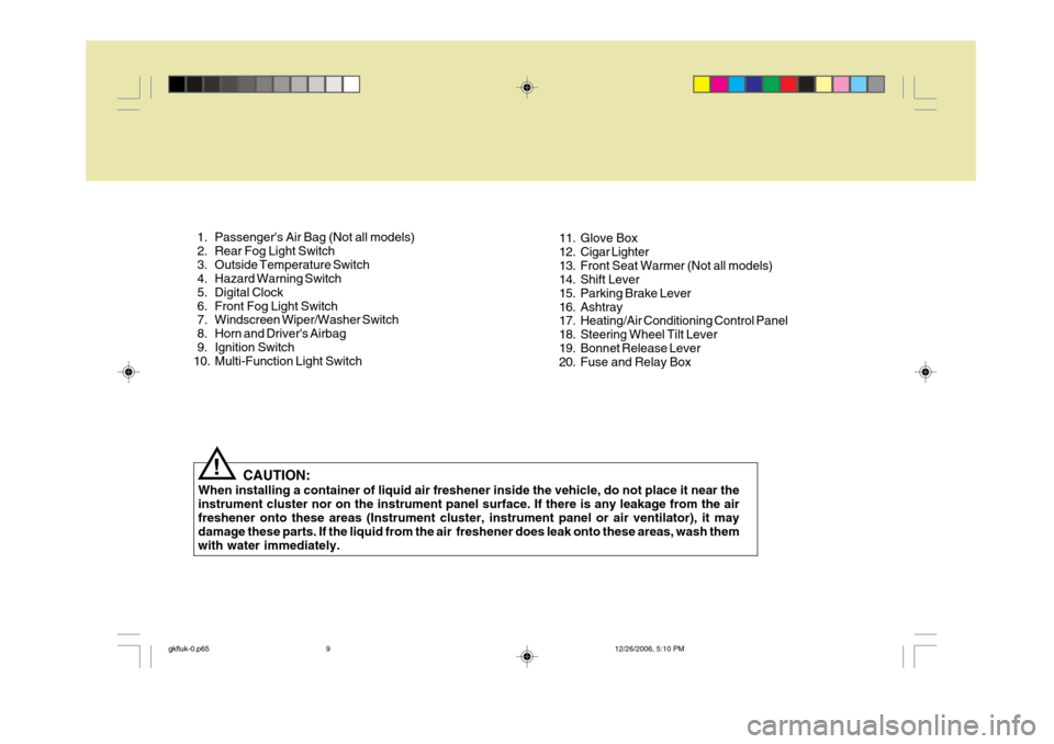
CAUTION:
When installing a container of liquid air freshener inside the vehicle, do not place it near the instrument cluster nor on the instrument panel surface. If there is any leakage from the air freshener onto these areas (Instrument cluster, instrument panel or air ventilator), it may damage these parts. If the liquid from the air freshener does leak onto these areas, wash themwith water immediately.!
1. Passenger's Air Bag (Not all models)
2. Rear Fog Light Switch
3. Outside Temperature Switch
4. Hazard Warning Switch
5. Digital Clock
6. Front Fog Light Switch
7. Windscreen Wiper/Washer Switch
8. Horn and Driver's Airbag
9. Ignition Switch
10. Multi-Function Light Switch
11. Glove Box
12. Cigar Lighter
13. Front Seat Warmer (Not all models)
14. Shift Lever
15. Parking Brake Lever
16. Ashtray
17. Heating/Air Conditioning Control Panel
18. Steering Wheel Tilt Lever
19. Bonnet Release Lever
20. Fuse and Relay Box
gkfluk-0.p65
12/26/2006, 5:10 PM
9
Page 268 of 483
1
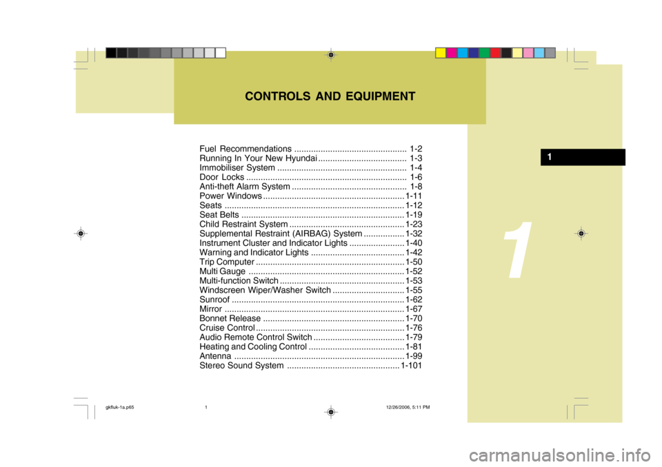
Fuel Recommendations ............................................... 1-2
Running In Your New Hyundai ..................................... 1-3
Immobiliser System ...................................................... 1-4
Door Locks ................................................................... 1-6
Anti-theft Alarm System ................................................ 1-8Power Windows........................................................... 1-11
Seats ........................................................................... 1-12
Seat Belts .................................................................... 1-19
Child Restraint System ................................................ 1-23
Supplemental Restraint (AIRBAG ) System................. 1-32
Instrument Cluster and Indicator Lights .......................1-40
Warning and Indicator Lights....................................... 1-42
Trip Computer .............................................................. 1-50
Multi Gauge ................................ ................................. 1-52
Multi-function Switch .................................................... 1-53
Windscreen Wiper/Washer Switch ..............................1-55
Sunroof ........................................................................ 1-62
Mirror ........................................................................... 1-67
Bonnet Release ........................................................... 1-70
Cruise Co ntrol.............................................................. 1-76
Audio Remote Contro l Switch ...................................... 1-79
Heating and Cooling Control .......... ..............................1-81
Antenna ....................................................................... 1-99
Stereo Sound System ............................................... 1-101
CONTROLS AND EQUIPMENT
1
gkfluk-1a.p65
12/26/2006, 5:11 PM
1
Page 302 of 483
1
CONTROLS AND EQUIPMENT
35
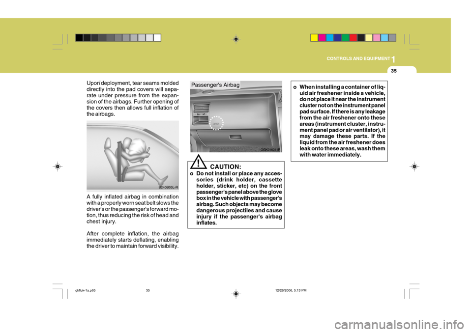
Passenger's Airbag
Upon deployment, tear seams molded directly into the pad covers will sepa-rate under pressure from the expan- sion of the airbags. Further opening of the covers then allows full inflation ofthe airbags. A fully inflated airbag in combination with a properly worn seat belt slows the driver's or the passenger's forward mo- tion, thus reducing the risk of head andchest injury. After complete inflation, the airbag immediately starts deflating, enabling the driver to maintain forward visibility. B240B03L-R
OGK016241R
!
CAUTION:
o Do not install or place any acces- sories (drink holder, cassette holder, sticker, etc) on the frontpassenger's panel above the glove box in the vehicle with passenger's airbag. Such objects may becomedangerous projectiles and cause injury if the passenger's airbag inflates.
o When installing a container of liq-
uid air freshener inside a vehicle, do not place it near the instrument cluster not on the instrument panelpad surface. If there is any leakage from the air freshener onto these areas (instrument cluster, instru-ment panel pad or air ventilator), it may damage these parts. If the liquid from the air freshener doesleak onto these areas, wash them with water immediately.
gkfluk-1a.p65 12/26/2006, 5:13 PM
35
Page 307 of 483
1CONTROLS AND EQUIPMENT
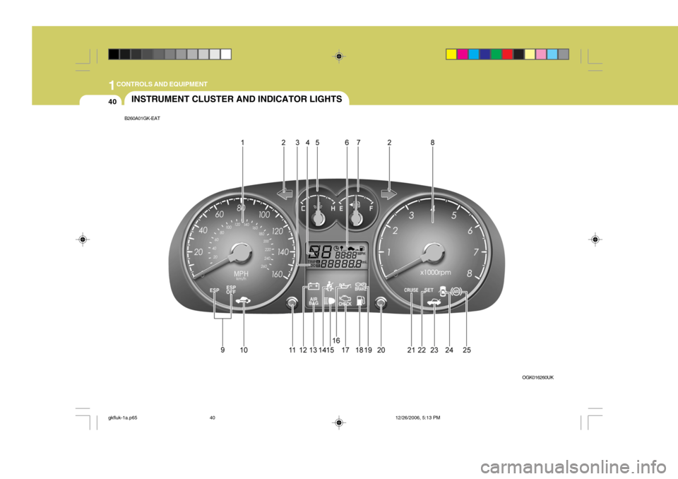
40INSTRUMENT CLUSTER AND INDICATOR LIGHTS
B260A01GK-EAT
OGK016260UK
gkfluk-1a.p6512/26/2006, 5:13 PM
40
Page 313 of 483
1CONTROLS AND EQUIPMENT
46
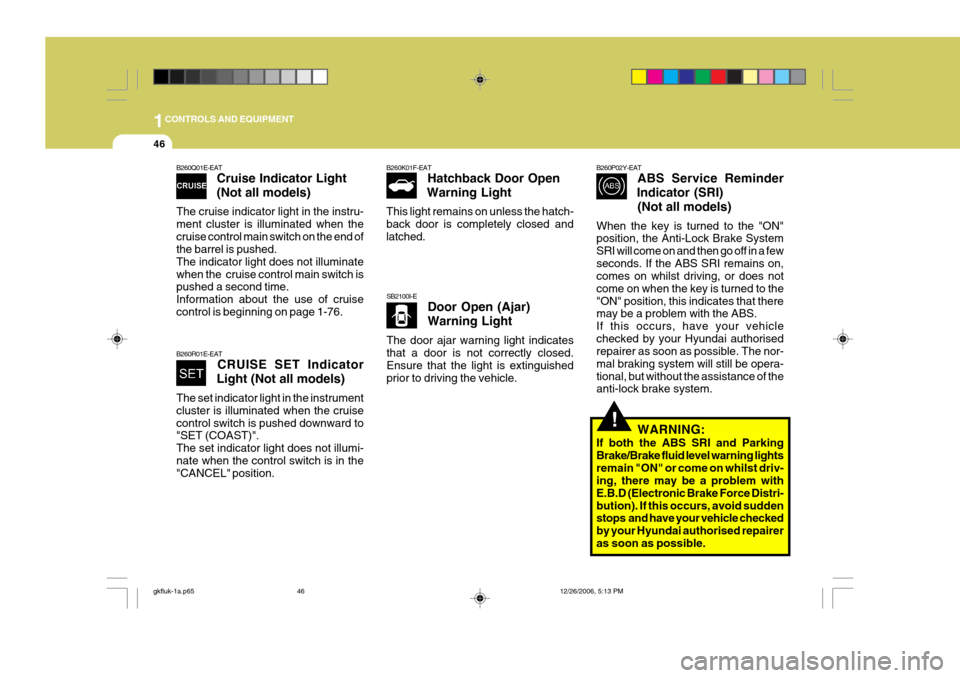
B260Q01E-EAT
Cruise Indicator Light (Not all models)
The cruise indicator light in the instru- ment cluster is illuminated when thecruise control main switch on the end of the barrel is pushed. The indicator light does not illuminatewhen the cruise control main switch is pushed a second time. Information about the use of cruisecontrol is beginning on page 1-76.
B260R01E-EAT CRUISE SET Indicator
Light (Not all models)
The set indicator light in the instrument cluster is illuminated when the cruisecontrol switch is pushed downward to "SET (COAST)". The set indicator light does not illumi-nate when the control switch is in the "CANCEL" position. B260K01F-EAT
Hatchback Door Open
Warning Light
This light remains on unless the hatch- back door is completely closed andlatched.
SB2100I-E Door Open (Ajar) Warning Light
The door ajar warning light indicates that a door is not correctly closed. Ensure that the light is extinguishedprior to driving the vehicle.
B260P02Y-EAT ABS Service Reminder
Indicator (SRI)
(Not all models)
When the key is turned to the "ON" position, the Anti-Lock Brake System SRI will come on and then go off in a fewseconds. If the ABS SRI remains on, comes on whilst driving, or does not come on when the key is turned to the"ON" position, this indicates that there may be a problem with the ABS. If this occurs, have your vehiclechecked by your Hyundai authorised repairer as soon as possible. The nor- mal braking system will still be opera-tional, but without the assistance of the anti-lock brake system.
WARNING:
If both the ABS SRI and Parking Brake/Brake fluid level warning lightsremain "ON" or come on whilst driv- ing, there may be a problem with E.B.D (Electronic Brake Force Distri-bution). If this occurs, avoid sudden stops and have your vehicle checked by your Hyundai authorised repaireras soon as possible.
!
gkfluk-1a.p65 12/26/2006, 5:13 PM
46
Page 314 of 483
1
CONTROLS AND EQUIPMENT
47
!
INSTRUMENT CLUSTER
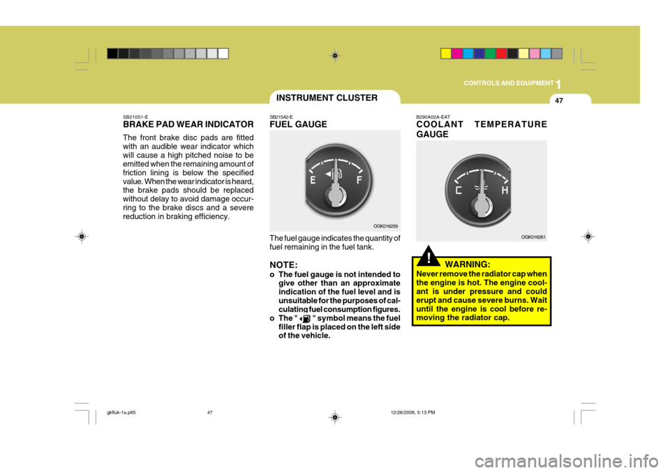
SB210S1-E BRAKE PAD WEAR INDICATOR The front brake disc pads are fitted with an audible wear indicator whichwill cause a high pitched noise to be emitted when the remaining amount of friction lining is below the specifiedvalue. When the wear indicator is heard, the brake pads should be replaced without delay to avoid damage occur-ring to the brake discs and a severe reduction in braking efficiency. SB215A2-E FUEL GAUGE The fuel gauge indicates the quantity of fuel remaining in the fuel tank. NOTE:
o The fuel gauge is not intended to
give other than an approximate indication of the fuel level and isunsuitable for the purposes of cal- culating fuel consumption figures.
o The "
" symbol means the fuel
filler flap is placed on the left side of the vehicle. B290A02A-EAT COOLANT TEMPERATURE GAUGE
WARNING:
Never remove the radiator cap when the engine is hot. The engine cool- ant is under pressure and could erupt and cause severe burns. Waituntil the engine is cool before re- moving the radiator cap.
OGK016259
OGK016261
gkfluk-1a.p65 12/26/2006, 5:13 PM
47
Page 320 of 483
1
CONTROLS AND EQUIPMENT
53MULTI FUNCTION SWITCH
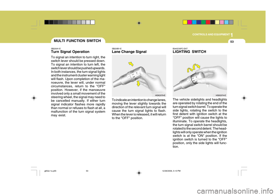
SB220A1-E Turn Signal Operation To signal an intention to turn right, the switch lever should be pressed down. To signal an intention to turn left, the switch lever should be pushed upwards.In both instances, the turn signal lights and the instrument cluster warning light will flash. Upon completion of the ma-noeuvre, the lever will, under normal circumstances, return to the "OFF" position. However, if the manoeuvreinvolved only a small movement of the steering wheel, the signal may need to be cancelled manually. If either turnsignal indicator flashes more rapidly than normal or refuses to flash at all, a malfunction of the turn signal systemmay exist. SB220B1-E Lane Change Signal To indicate an intention to change lanes, moving the lever slightly towards the direction of the relevant turn signal will cause the turn signal lights to flash.When the lever is released, it will return to the "OFF" position.B340C05FC-EAT LIGHTING SWITCH The vehicle sidelights and headlights are operated by rotating the end of the turn signal switch barrel. To operate theside lights, rotating the switch to the first detent with ignition switch at the "OFF" position will cause the lights toilluminate. To operate the headlights, the turn signal switch barrel should be rotated to the second detent. The head-lights will only operate when the ignition switch is at the "ON" position. If the ignition switch is turned to the "OFF"position, only the side lights will func- tion.
HGK2079-EHGK2074-E
gkfluk-1a.p65
12/26/2006, 5:13 PM
53
Page 345 of 483
1CONTROLS AND EQUIPMENT
78
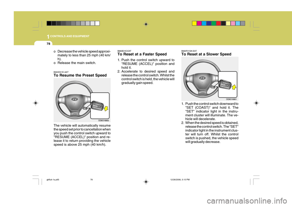
B660E01E-EAT To Reset at a Faster Speed
1. Push the control switch upward to
"RESUME (ACCEL)" position and hold it.
2. Accelerate to desired speed and
release the control switch. Whilst thecontrol switch is held, the vehicle will gradually gain speed. B660F01GK-EAT To Reset at a Slower Speed
1. Push the control switch downward to
"SET (COAST)" and hold it. The "SET" indicator light in the instru-ment cluster will illuminate. The ve- hicle will decelerate.
2. When the desired speed is obtained, release the control switch. The "SET"indicator light in the instrument clus- ter will turn off. Whilst the controlswitch is pushed, the vehicle speed will gradually decrease. OGK016661
o Decrease the vehicle speed approxi-
mately to less than 25 mph (40 km/ h).
o Release the main switch. B660D01E-AAT To Resume the Preset Speed The vehicle will automatically resume the speed set prior to cancellation when you push the control switch upward to"RESUME (ACCEL)" position and re- lease it to return providing the vehicle speed is above 25 mph (40 km/h).
OGK016663
gkfluk-1a.p65 12/26/2006, 5:15 PM
78
Page 382 of 483
2DRIVING YOUR HYUNDAI
10
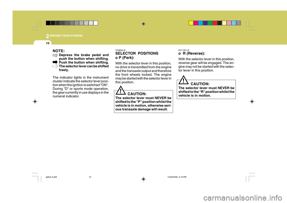
NOTE:Depress the brake pedal and push the button when shifting. Push the button when shifting.The selector lever can be shifted freely.
The indicator lights in the instrumentcluster indicate the selector lever posi- tion when the ignition is switched "ON".During "D" or sports mode operation, the gear currently in use displays in the numeral indicator.
YC090A1-E SELECTOR POSITIONS o P (Park): With the selector lever in this position, no drive is transmitted from the engineand the transaxle output and therefore the front wheels locked. The engine may be started with the selector lever inthis position.
CAUTION:
The selector lever must NEVER beshifted to the "P" position whilst thevehicle is in motion, otherwise seri- ous transaxle damage will result.
! DC110C1-E o R (Reverse): With the selector lever in this position, reverse gear will be engaged. The en-gine may not be started with the selec- tor lever in this position.
CAUTION:
The selector lever must NEVER be shifted to the "R" position whilst thevehicle is in motion.
!
gkfluk-2.p65 12/26/2006, 5:19 PM
10