check oil Hyundai Coupe 2006 Owner's Guide
[x] Cancel search | Manufacturer: HYUNDAI, Model Year: 2006, Model line: Coupe, Model: Hyundai Coupe 2006Pages: 483, PDF Size: 12.73 MB
Page 226 of 483
6
DO-IT-YOURSELF MAINTENANCE
27
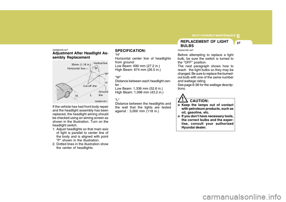
G290B02GK-GAT
Adjustment After Headlight As- sembly Replacement
If the vehicle has had front body repair and the headlight assembly has been replaced, the headlight aiming should be checked using an aiming screen asshown in the illustration. Turn on the headlight switch.
1. Adjust headlights so that main axis of light is parallel to center line of the body and is aligned with point"P" shown in the illustration.
2. Dotted lines in the illustration show the center of headlights. SPECIFICATION:
"H" Horizontal center line of headlights
from ground:
Low Beam: 690 mm (27.2 in.) High Beam: 674 mm (26.5 in.) "W" Distance between each headlight cen-
ter :
Low Beam: 1,336 mm (52.6 in.) High Beam: 1,098 mm (43.2 in.) "L" Distance between the headlights and
the wall that the lights are tested against : 3,000 mm (118 in.)
G290B01HR-1
H
Ground line
30mm (1.18 in.)
L
Cut-off line "P"
Horizontal line
H
W
Vertical line
REPLACEMENT OF LIGHT BULBS
G260A01MC-AAT Before attempting to replace a light
bulb, be sure the switch is turned to the "OFF" position.
The next paragraph shows how to
reach the light bulbs so they may bechanged. Be sure to replace the burned- out bulb with one of the same number and wattage rating.
See page 6-36 for the wattage descrip-
tions.
CAUTION:
o Keep the lamps out of contact with petroleum products, such asoil, gasoline, etc.
o If you don't have necessary tools, the correct bulbs and the exper- tise, consult your authorized Hyundai dealer.
!
Page 255 of 483

10
INDEX
3
Driving Economical driving .................................................. 2-16
Smooth corneri ng ..................................................... 2-17
Winter driving ........................................................... 2-17
E Electronic Stability Program (ESP) ............................2-13
Emissions Control Systems ........................................ 7-2 Engine Before starting the engine ........................................ 2-3
Changing the oil and filter ......................................... 6-6Compartment (1.6L, 2.0L, 2.7L) ................................ 6-2
Coolant ..................................................................... 6-9
Coolant temperature gauge ......................................1-50
If the engine overheats ............................................. 3-4
Number ..................................................................... 8-2
Oil ............................................................................. 6-6Oil consumption ........................................................ 6-8
Starting ..................................................................... 2-5
Engine Exhaust Can Be Dangerous ............................ 2-2
FFog Light .................................................................... 1-60
Front Seats Adjustable front seats .............................................. 1-13
Adjustable headrests ............................................... 1-14
Adjusting seat forward and rearward ........................ 1-13
Adjusting seatback angle ........................................ 1-14
Lumbar support control ............................................ 1-16
Seat cushion height adjustment .............................. 1-16Seat warmer
............................................................ 1-16
Fuel Capacity ................................................................... 9-2
Gauge ...................................................................... 1-50
Recommendations .................................................... 1-2
Fuel Filler Lid Remote release ....................................................... 1-74
Fuse Panel Description .............................................. 6-37
Fuses ......................................................................... 6-21
G
General Everyday Checks ..... ...................................... 6-5
Glove box ................................................................... 1-69
H Hazard Warning System ............................................. 1-61
Headlight Leveling Device S ystem .............................1-64
Heating and Air Conditioning Control Rotary type .............................................................. 1-84
Automatic type ........................................................ 1-93
High-mounted rear stoplight .. ......................................1-72
Hood Release ............................................................. 1-73
Horn ............................................................................ 1-78
I Ignition Switch ............................................................. 2-4
Immobilizer System ..................................................... 1-4
Instrument Cluster and Indicator Lights ...................... 1-42
Instrument Panel Light Control (Rheostat) .................. 1-62
Intermittent Wiper ....................................................... 1-59
Page 270 of 483
1
CONTROLS AND EQUIPMENT
3RUNNING IN YOUR NEW HYUNDAI
B020A01S-EAT The longevity and performance of the vehicle are greatly affected by the care exercised during the first 1,000 miles of motoring. Because of modern manu-facturing techniques, rigid guidelines regarding maximum road speeds have become unnecessary. However, cer-tain precautions should be observed in order to obtain the best possible per- formance and useful life from the ve-hicle.
1) Do not race the engine without a
load (i.e revving the engine in neu- tral).
2) During the first 500 miles the maxi- mum engine speed should be re-stricted to 3,000 rpm and gradually increased thereafter.
3) Avoid prolonged constant speed operation. The internal componentsof the engine will become morequickly run in if the operation speed is varied during the running in pe- riod.
4) Never allow the engine to labour. Use the gearbox freely and avoidlarge throttle openings when theengine speed is below 1,500 rpm.BEFORE ENTERING THE VEHICLEAFTER ENTERING THE VEHICLE
YB020A1-E
o Ensure that all windows, mirrors
and lamps are clean.
o Check condition of all tyres.
o Ensure that no fluid leaks are evi-
dent.
o Ensure that the area around the vehicle is clear before driving off. YB020B1-E
o Ensure that all occupants fasten
and correctly adjust seat belts.
o Ensure that seat and head restraint positions are adjusted for optimum safety, control and comfort.
o Adjust interior and exterior rear view mirrors.
o Verify correct operation of lamps, horn and other electrical equipment.
o Ensure that warning lamps illumi-
nate when ignition is turned on.
NOTE: Fluid levels such as engine oil, en- gine coolant, brake and windscreenwasher fluid should be checked daily or at each refuelling, which- ever occurs sooner.
gkfluk-1a.p65 12/26/2006, 5:11 PM
3
Page 310 of 483
1
CONTROLS AND EQUIPMENT
43
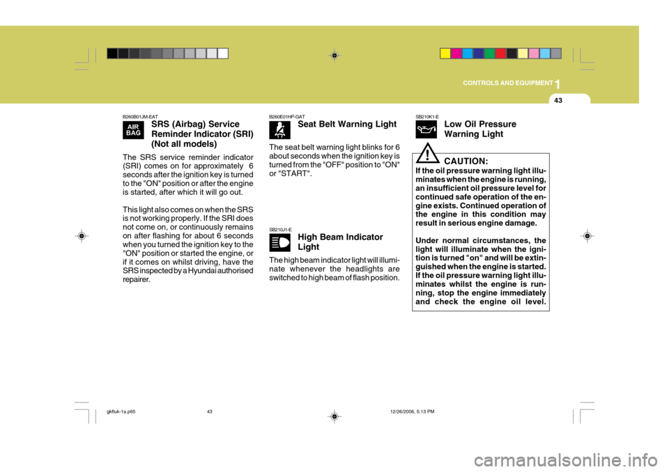
B260B01JM-EAT SRS (Airbag) Service Reminder Indicator (SRI)(Not all models)
The SRS service reminder indicator (SRI) comes on for approximately 6 seconds after the ignition key is turnedto the "ON" position or after the engine is started, after which it will go out. This light also comes on when the SRS is not working properly. If the SRI does not come on, or continuously remainson after flashing for about 6 seconds when you turned the ignition key to the "ON" position or started the engine, orif it comes on whilst driving, have the SRS inspected by a Hyundai authorised repairer.
B260E01HP-GAT Seat Belt Warning Light
The seat belt warning light blinks for 6 about seconds when the ignition key isturned from the "OFF" position to "ON" or "START".
SB210J1-E High Beam Indicator Light
The high beam indicator light will illumi- nate whenever the headlights areswitched to high beam of flash position.
SB210K1-E Low Oil Pressure Warning Light
!CAUTION:
If the oil pressure warning light illu- minates when the engine is running, an insufficient oil pressure level for continued safe operation of the en-gine exists. Continued operation of the engine in this condition may result in serious engine damage. Under normal circumstances, the light will illuminate when the igni- tion is turned "on" and will be extin- guished when the engine is started.If the oil pressure warning light illu- minates whilst the engine is run- ning, stop the engine immediatelyand check the engine oil level.
gkfluk-1a.p65 12/26/2006, 5:13 PM
43
Page 311 of 483
1CONTROLS AND EQUIPMENT
44
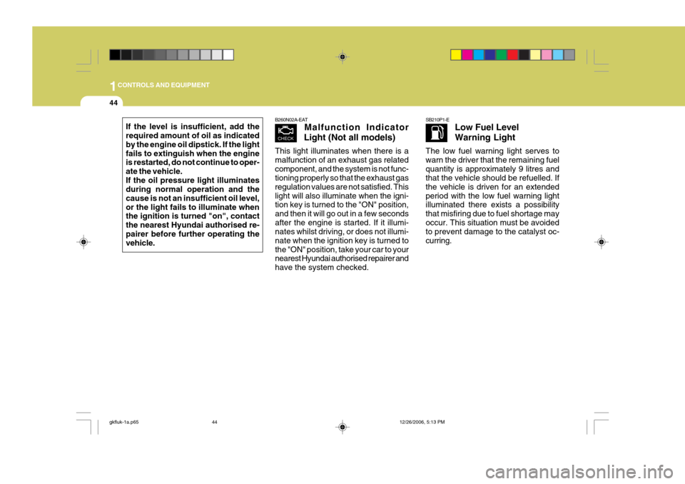
If the level is insufficient, add the required amount of oil as indicated by the engine oil dipstick. If the lightfails to extinguish when the engine is restarted, do not continue to oper- ate the vehicle.If the oil pressure light illuminates during normal operation and the cause is not an insufficient oil level,or the light fails to illuminate when the ignition is turned "on", contact the nearest Hyundai authorised re-pairer before further operating the vehicle.
B260N02A-EAT Malfunction Indicator
Light (Not all models)
This light illuminates when there is a malfunction of an exhaust gas relatedcomponent, and the system is not func- tioning properly so that the exhaust gas regulation values are not satisfied. Thislight will also illuminate when the igni- tion key is turned to the "ON" position, and then it will go out in a few secondsafter the engine is started. If it illumi- nates whilst driving, or does not illumi- nate when the ignition key is turned tothe "ON" position, take your car to your nearest Hyundai authorised repairer and have the system checked.SB210P1-E Low Fuel Level Warning Light
The low fuel warning light serves to warn the driver that the remaining fuelquantity is approximately 9 litres and that the vehicle should be refuelled. If the vehicle is driven for an extendedperiod with the low fuel warning light illuminated there exists a possibility that misfiring due to fuel shortage mayoccur. This situation must be avoided to prevent damage to the catalyst oc- curring.
gkfluk-1a.p65 12/26/2006, 5:13 PM
44
Page 375 of 483
2
DRIVING YOUR HYUNDAI
3TO START THE ENGINEBEFORE STARTING THE ENGINE
SC030A2-E Before you start the engine, you should always:
1. Look around the vehicle to be sure
there are no flat tyres, puddles of oil or water or other indications of pos- sible trouble.
2. After entering the car, check to be sure the parking brake is engaged.
3. Check that all windows, and lights
are clean.
4. Check that the interior and exterior mirrors are clean and in position.
5. Check your seat, seatback and head restraint to be sure they are intheir proper positions.
6. Close all the doors.
7. Fasten your seat belt and be sure that all other occupants have fas-tened theirs.
8. Turn off all lights and accessories that are not needed.
9. When you turn the ignition switch to "ON" check that all appropriate warn- ing lights are operating and that you have sufficient fuel.
10.Check the operation of warning lights and all bulbs when key is inthe "ON" position.
!WARNING:
Always wear appropriate shoes when operating your vehicle.Unsuitable shoes (high heels, ski boots, etc.) may interfere with your ability to use the brake and accelera-tor pedal, and the clutch (Not all models). C030A01A-EAT COMBINATION IGNITION SWITCH AND STEERING LOCK
o If your Hyundai is equipped with a
manual transaxle, place the gear- shift lever in neutral and depress the clutch pedal fully.
o If your Hyundai has an automatic
transaxle, place the selector lever in"P" (park).
o To start the engine, insert the ignition key and turn it to the "START" posi-tion. Release it as soon as the en- gine starts. Do not hold the key in the"START" position for more than 15 seconds.
NOTE: For safety, the engine will not start if the shift lever is not in "P" or "N" position (Automatic Transaxle).
gkfluk-2.p65 12/26/2006, 5:19 PM
3
Page 400 of 483
3
IN CASE OF EMERGENCY
3
!
!
D010C01A-EAT If Engine Turns Over Normally but Does Not Start
1. Check fuel level.
2. With the key in the off position,
Check all connectors at ignition coils and spark plugs. Reconnect any that may be disconnected or loose.
3. Check the fuel line in the engine room.
4. If engine still refuses to start, call a Hyundai authorised repairer or seek other qualified assistance.
D010D01A-EAT If Engine Stalls While Driving
1. Reduce your speed gradually, keep- ing a straight line. Move cautiously off the road to a safe place.
2. Turn on your hazard lights.
3. Try to start the engine again. If your vehicle will not start, contact aHyundai authorised repairer or seekother qualified assistance. SD030A2-E
CAUTION:
Personal injury and damage to thevehicle may occur if jump startingis not performed correctly. If any doubt exists as to how this opera- tion should be performed, seek as-sistance from qualified personnel.
JUMP STARTING
WARNING:
Motor vehicle batteries contain sulphuric acid and emit hydrogen gas. Protective clothing should beworn and care exercised to prevent the acid from coming into contact with skin or clothing and the ve-hicle. Naked lights should not be permitted in the vicinity of the bat- tery. Care should be exercised toprevent sparks occurring during connection. If acid accidentally comes into contact with skin oreyes, the affected area should im- mediately be flushed with copious amounts of water and medical as-sistance sought.
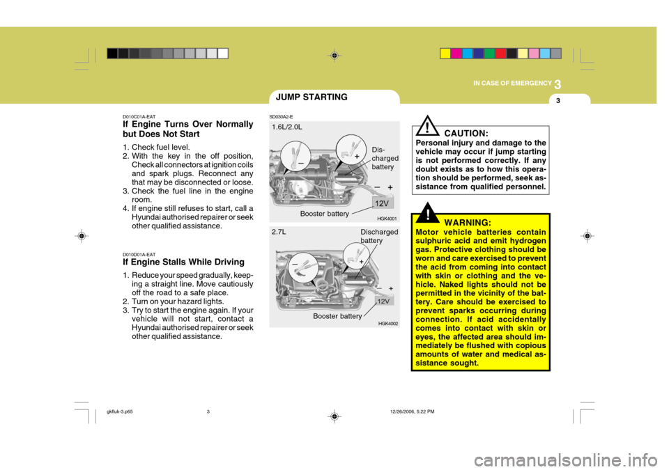
1.6L/2.0L
HGK4001
HGK4002
Dis- chargedbattery
2.7L Booster battery
Discharged battery
Booster battery
gkfluk-3.p65 12/26/2006, 5:22 PM
3
Page 402 of 483
3
IN CASE OF EMERGENCY
5
!
!WARNING:
Whilst the engine is running, keep hands and clothing away from mov- ing parts such as the fan and drive belts to prevent injury.
5. If the water pump drive belt is broken or coolant is leaking out, stop the engine immediately and call the near- est Hyundai authorised repairer forassistance.
WARNING:
Do not remove the radiator cap when the engine is hot since steam and boiling water may be ejected fromthe radiator resulting in burns or scalding.
!
6. If the cause of the overheating can- not be found, wait until the engine temperature has returned to normal. Then, if coolant has been lost, care- fully add coolant to the reservoir(page 6-10) to bring the fluid level in the reservoir up to the base of the radiator fill opening. Fill the coolantexpansion tank to the halfway mark. To ensure the correct water to cool- ant mix is obtained after top up,testing by an authorised repairer is required.
7. Proceed with caution until it is estab- lished that the engine is operatingnormally. If the engine overheats repeatedly, the advice of a Hyundaiauthorised repairer should be sought.
CAUTION:
Serious loss of coolant indicates there is a leak in the cooling system and this should be checked as soonas possible by a Hyundai authorised repairer.D040A01GK-EAT The following instructions for the tem- porary spare tyre should be observed:
1. Check inflation pressure as soon as practical after installing the spare tyre, and adjust to the specified pressure. The tyre pressure shouldbe periodically checked and main- tained at the specified pressure whilst the tyre is stored.
TEMPORARY SPARE TYRE
Tyre Size
Inflation Pressure T125/70 R16
420 kPa (60 psi)
Spare Tyre Pressure
2. The spare tyre should only be used temporarily and should be returned to the luggage compartment as soonas the original tyre can be repaired or replaced.
3. Continuous use at speeds of over 50 mph (80 km/h) is not recom-mended.
4. As the temporary spare tyre is spe- cifically designed for your car, itshould not be used on any other vehicle.
gkfluk-3.p65 12/26/2006, 5:22 PM
5
Page 418 of 483
5VEHICLE MAINTENANCE REQUIREMENTS
2MAINTENANCE AND SER- VICING REQUIREMENTS
SF020A1-E To ensure the continued reliability and safety of the vehicle, certain routinemaintenance operations are required at specific mileage or time intervals. It is the responsibility of the vehicle owner to ensure that the maintenance schedules shown in both this OwnersManual and the Warranty and Service Passport are adhered to. The new vehicle warranty may be invalidated if the routine maintenance operations are not performed in line with the recommendations outlined andthe safety and durability of the vehicle adversely affected. It is recommended that all mainte- nance operations with the exception of the daily operating checks are en-trusted to a Hyundai authorised re- pairer to ensure that the latest repair and maintenance procedures andspecialised servicing tools are em- ployed. In addition, the use of genuine Hyundai replacement parts will ensurethat the vehicle safety and perfor- mance will not be compromised. NOTE:
The inspection and testing of cer-
tain electronic fuel injection/enginemanagement and automatic trans- mission control systems requirespecialised electronic equipment specifically designed for Hyundai vehicles. The use of general pur-pose electrical test equipment may result in damage to the control unit microprocessors. SF020C2-E
Specified Scheduled Procedures
The Specified scheduled procedures
are listed in the maintenance charts beginning at page 5-4. The operations specified must be performed at thetime or mileage intervals shown irre- spective of whether the mileage inter- val has been reached before the speci-fied time interval.
Certain lubricants and components
degrade with both time and mileage (e.g. engine oil and brake fluid) and therefore it is not permissable to basethe maintenance schedule upon mile- age alone. It is strongly recommended that the maintenance operations areperformed by the factory-trained or distributor-trained technicians at your Hyundai authorised repairer becauseof the need for specialised knowledge and tooling and to ensure that no possibility of invalidating the manufac-turers warranty exists. The maintenance schedules relate to
vehicles operated under normal condi-tions, vehicles which are operated under adverse conditions will require more frequent maintenance which isdescribed at page 5-7.
gkfluk-5.p65 12/26/2006, 5:23 PM
2
Page 422 of 483
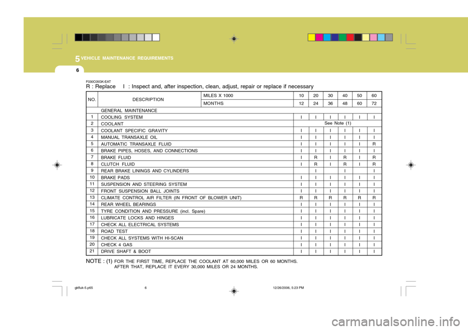
5VEHICLE MAINTENANCE REQUIREMENTS
6
NO.1 2345 6 789
1011 12 1314151617 18 192021 DESCRIPTION
GENERAL MAINTENANCECOOLING SYSTEM COOLANT COOLANT SPECIFIC GRAVITYMANUAL TRANSAXLE OILAUTOMATIC TRANSAXLE FLUIDBRAKE PIPES, HOSES, AND CONNECTIONSBRAKE FLUID CLUTCH FLUID REAR BRAKE LININGS AND CYLINDERSBRAKE PADSSUSPENSION AND STEERING SYSTEMFRONT SUSPENSION BALL JOINTSCLIMATE CONTROL AIR FILTER (IN FRONT OF BLOWER UNIT) REAR WHEEL BEARINGS TYRE CONDITION AND PRESSURE (incl. Spare)LUBRICATE LOCKS AND HINGESCHECK ALL ELECTRICAL SYSTEMSROAD TESTCHECK ALL SYSTEMS WITH HI-SCAN CHECK 4 GAS DRIVE SHAFT & BOOT
F030C05GK-EAT R : Replace I : Inspect and, after inspection, clean, adjust, repair or replace if necessary
60 72
I I I
R
I
RR IIII
R I I IIIII I
50 60
I I IIIII I II
R
I I IIIII I
40 48
I I III
RR IIII
R I I IIIII I
30 36
I I IIIII I II
R I I IIIII I
20 24
I I III
RR IIII
R I I IIIII I
10 12
I I IIIII I II
R
I I IIIII I
MILES X 1000 MONTHS
NOTE : (1)
FOR THE FIRST TIME, REPLACE THE COOLANT AT 60,000 MILES OR 60 MONTHS. AFTER THAT, REPLACE IT EVERY 30,000 MILES OR 24 MONTHS. See Note (1)
gkfluk-5.p65
12/26/2006, 5:23 PM
6