fuel cap Hyundai Elantra 2006 Owner's Manual
[x] Cancel search | Manufacturer: HYUNDAI, Model Year: 2006, Model line: Elantra, Model: Hyundai Elantra 2006Pages: 277, PDF Size: 10.18 MB
Page 67 of 277
1
FEATURES OF YOUR HYUNDAI
53
!
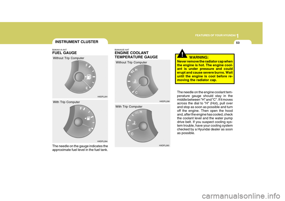
B280A01A-AAT FUEL GAUGE The needle on the gauge indicates the approximate fuel level in the fuel tank. B290A02E-AAT ENGINE COOLANT TEMPERATURE GAUGE
Without Trip Computer With Trip Computer HXDFL291
HXDFL290
HXDFL284 HXDFL283
Without Trip Computer
With Trip Computer WARNING:
Never remove the radiator cap when the engine is hot. The engine cool- ant is under pressure and could erupt and cause severe burns. Waituntil the engine is cool before re- moving the radiator cap. The needle on the engine coolant tem- perature gauge should stay in themiddle between "H" and "C". If it moves across the dial to "H" (Hot), pull over and stop as soon as possible and turnoff the engine. Then open the hood and, after the engine has cooled, check the coolant level and the water pumpdrive belt. If you suspect cooling sys- tem trouble, have your cooling system checked by a Hyundai dealer as soonas possible.
INSTRUMENT CLUSTER
Page 94 of 277
1FEATURES OF YOUR HYUNDAI
80
!WARNING:
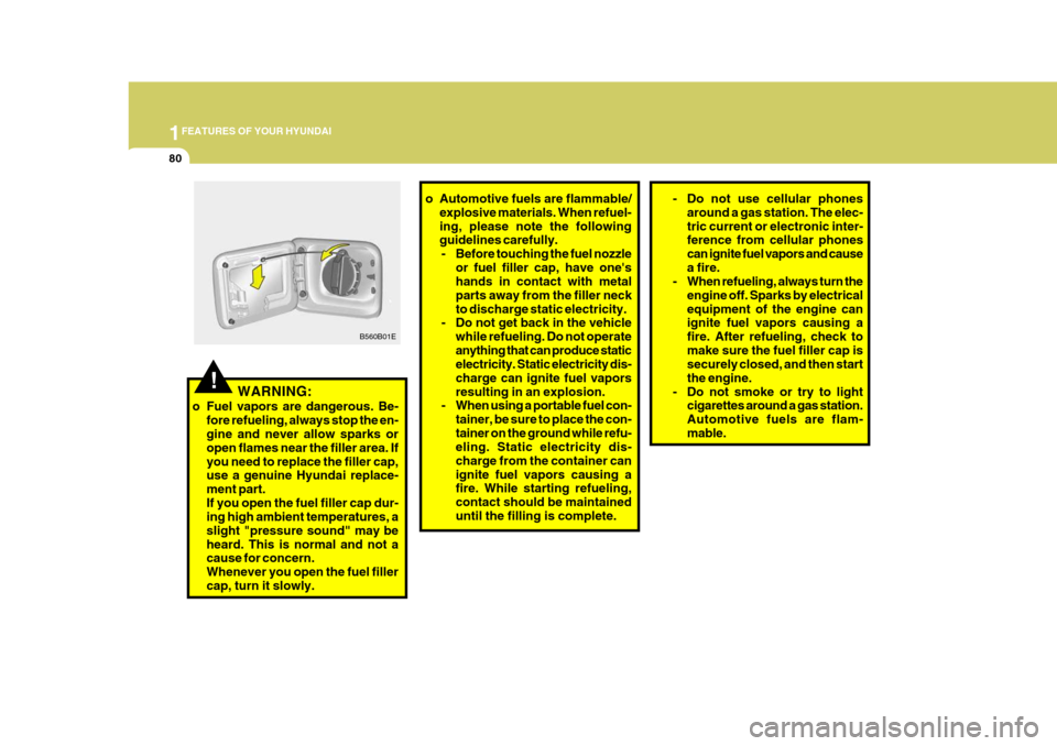
o Fuel vapors are dangerous. Be- fore refueling, always stop the en- gine and never allow sparks or open flames near the filler area. Ifyou need to replace the filler cap, use a genuine Hyundai replace- ment part.If you open the fuel filler cap dur- ing high ambient temperatures, a slight "pressure sound" may beheard. This is normal and not a cause for concern. Whenever you open the fuel fillercap, turn it slowly. B560B01E
o Automotive fuels are flammable/
explosive materials. When refuel- ing, please note the following guidelines carefully.- Before touching the fuel nozzle or fuel filler cap, have one'shands in contact with metal parts away from the filler neckto discharge static electricity.
- Do not get back in the vehicle
while refueling. Do not operateanything that can produce static electricity. Static electricity dis- charge can ignite fuel vaporsresulting in an explosion.
- When using a portable fuel con-
tainer, be sure to place the con-tainer on the ground while refu- eling. Static electricity dis- charge from the container canignite fuel vapors causing a fire. While starting refueling, contact should be maintaineduntil the filling is complete.- Do not use cellular phonesaround a gas station. The elec- tric current or electronic inter- ference from cellular phones can ignite fuel vapors and causea fire.
- When refueling, always turn the
engine off. Sparks by electricalequipment of the engine can ignite fuel vapors causing a fire. After refueling, check tomake sure the fuel filler cap is securely closed, and then start the engine.
- Do not smoke or try to light cigarettes around a gas station.Automotive fuels are flam-mable.
Page 184 of 277
3
WHAT TO DO IN AN EMERGENCY
5
!
!
!
check for coolant leaking from the radiator, hoses or under the car. (Ifthe air conditioning had been in use, it is normal for cold water to be draining from it when you stop).
WARNING:
While the engine is running, keephair, hands, and clothing away from moving parts such as the fan and drive belts to prevent injury. 5. If the water pump drive belt is broken
or coolant is leaking out, stop the engine immediately and call the near- est Hyundai dealer for assistance.
WARNING:
Do not remove the radiator cap when the engine is hot. This can allow coolant to be blown out of the open-ing and cause serious burns.
WARNING (Diesel only):
Never work on injection system withengine running or within 30 sec- onds after shutting off engine. High pressure pump, rail, injectors andhigh pressure pipes are subject to high pressure even after the engine stopped. The fuel jet produced byfuel leaks may cause serious in- jury, if it touch the body. People using pacemakers should not movethan 30cm closer to the ECU or wiring harness within the engine
!
6. If you cannot find the cause of the overheating, wait until the engine temperature has returned to nor-mal. Then, if the engine coolant has been lost, carefully add coolant to the reservoir (page 6-16) to bringthe fluid level in the reservoir up to the halfway mark. CAUTION:
Serious loss of engine coolant indi- cates there is a leak in the coolingsystem and this should be checked as soon as possible by a Hyundai dealer.
room while engine is running, sincethe high currents in the CommonRail system produce considerable magnetic fields.
7. Proceed with caution, keeping alert
for further signs of overheating. If overheating happens again, call a Hyundai dealer for assistance.
Page 202 of 277
5VEHICLE MAINTENANCE REQUIREMENTS
4
NO.
1 23 4 5 6 7 8 9
10 DESCRIPTION
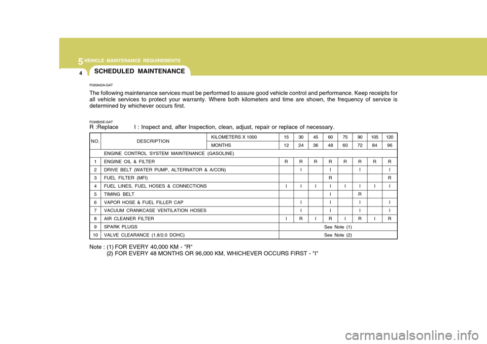
ENGINE CONTROL SYSTEM MAINTENANCE (GASOLINE) ENGINE OIL & FILTER DRIVE BELT (WATER PUMP, ALTERNATOR & A/CON)FUEL FILTER (MFI) FUEL LINES, FUEL HOSES & CONNECTIONS TIMING BELT VAPOR HOSE & FUEL FILLER CAP VACUUM CRANKCASE VENTILATION HOSES AIR CLEANER FILTER SPARK PLUGS VALVE CLEARANCE (1.8/2.0 DOHC)
F030A02A-GAT The following maintenance services must be performed to assure good vehicle control and performance. Keep receipts for all vehicle services to protect your warranty. Where both kilometers and time are shown, the frequency of service is determined by whichever occurs first. F030B05E-GAT R :Replace I : Inspect and, after Inspection, clean, adjust, repair or replace of necessary.105
84
R
I I 120
96
R I
R I I I
R
90
72
R I I
R I I
R
75
60
R
I I
60
48
R I
R I I I I
R
45
36
R
I I
30
24
R I II I
R
15
12
R
I I
KILOMETERS X 1000 MONTHS
See Note (1) See Note (2)
Note : (1) FOR EVERY 40,000 KM - "R" (2) FOR EVERY 48 MONTHS OR 96,000 KM, WHICHEVER OCCURS FIRST - "I"
SCHEDULED MAINTENANCE
Page 207 of 277
5
VEHICLE MAINTENANCE REQUIREMENTS
9
F060H01A-AAT
o Air Cleaner Filter A Genuine Hyundai air cleaner filter is
recommended when the filter is re- placed. F060J01A-AAT
o Spark Plugs Make sure to install new spark plugs of the correct heat range. F070B01A-GAT
o Cooling System Check the cooling system part, such as radiator, coolant reservoir, hosesand connections for leakage and dam- age. Replace any damaged parts.
F060E01A-AAT
o Timing Belt
Inspect all parts related to the timing belt for damage and deformation. Replace any damaged parts immedi- ately. F060G01A-AAT
o Vapor Hose and Fuel Filler Cap
The vapor hose and fuel filler cap should be inspected at those inter- vals specified in the maintenanceschedule. Make sure that a new va- por hose or fuel filler cap is correctly replaced. F060F01A-AAT
o Vacuum, Crankcase Ventila-
tion Hoses
Inspect the surface of hoses for evi-
dence of heat and/or mechanical dam- age. Hard and brittle rubber, crack- ing, tears, cuts, abrasions, and ex-cessive swelling indicate deteriora- tion. Particular attention should be paid to examine those hose surfacesnearest to high heat sources, such as the exhaust manifold.
Inspect the hose routing to assure that
the hoses do not come in contact withany heat source, sharp edges or mov- ing component which might cause heatdamage or mechanical wear. Inspect all hose connections, such as clamps and couplings, to make sure they aresecure, and that no leaks are present. Hoses should be replaced immedi- ately if there is any evidence of dete-rioration or damage. F060N02E-GAT
o Valve Clearance
Inspect excessive valve noise and/or engine vibration and adjust if neces- sary. A qualified technician shouldperform the operation.
Page 215 of 277
6 DO-IT-YOURSELF MAINTENANCE
6
7 9 10 11
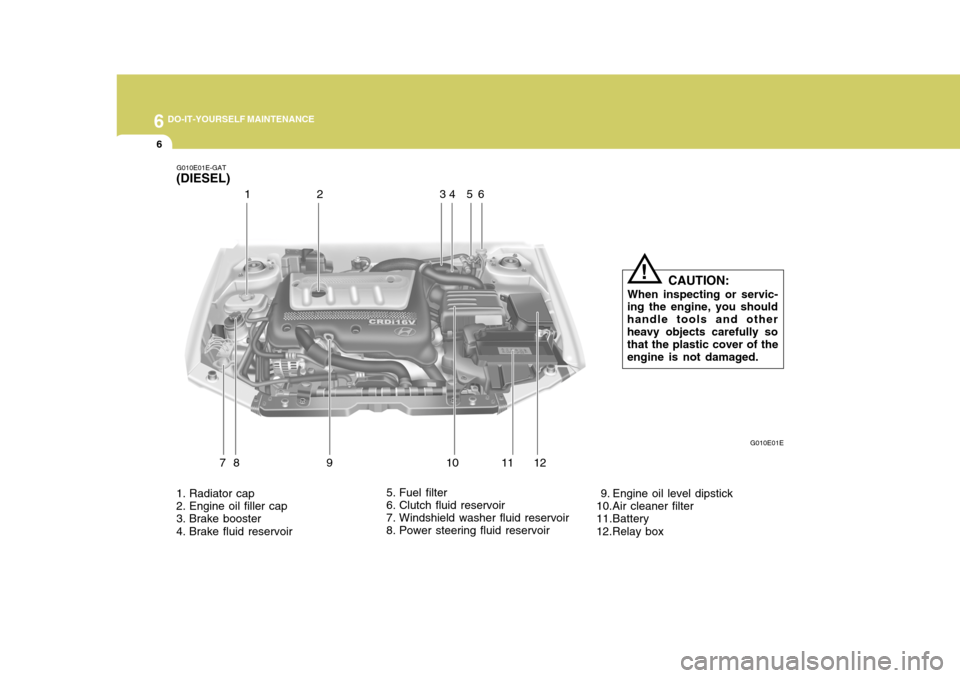
81
2
1. Radiator cap
2. Engine oil filler cap
3. Brake booster
4. Brake fluid reservoir 5. Fuel filter
6. Clutch fluid reservoir
7. Windshield washer fluid reservoir
8. Power steering fluid reservoir
9. Engine oil level dipstick
10.Air cleaner filter
11.Battery 12.Relay boxG010E01E
G010E01E-GAT
(DIESEL)
1 23
456
CAUTION:
When inspecting or servic-
ing the engine, you should handle tools and otherheavy objects carefully so that the plastic cover of the engine is not damaged.
!
Page 259 of 277
7EMISSION CONTROL SYSTEMS
2EMISSION CONTROL SYSTEMS
H010A01A-GAT
(If installed)
Your Hyundai is equipped with an
emission control system to meet all requirements of the Emission prohibi- tion rules of your province.
There are three emission control sys-
tems which are as follows.
(1) Crankcase emission control sys- tem
(2) Evaporative emission control sys- tem
(3) Exhaust emission control system
In order to assure the proper function
of the emission control systems, it is recommended that you have your carinspected and maintained by an au- thorized Hyundai dealer in accordance with the maintenance schedule in thismanual. H010B01A-AAT
1. Crankcase Emission Control
System
The positive crankcase ventilation
system is employed to prevent airpollution caused by blow-by gasesbeing emitted from the crankcase. This system supplies fresh filtered air to the crankcase through the air in-take hose. Inside the crankcase, the fresh air mixes with blow-by gases, then passes through the PCV valveinto the induction system.
H010C02E-GAT
2. Evaporative Emission
Control System
The Evaporative Emission Control
System is designed to prevent fuel vapors from escaping into the atmo- sphere. Canister
While the engine is inoperative, fuel
vapors generated inside the fuel tank are absorbed and stored in the canis-ter. When the engine is running, the fuel vapors absorbed in the canister are drawn into the induction system through the purge control solenoid valve. Purge Control Solenoid Valve (PCSV)
The purge control solenoid valve is
controlled by the Engine Control Mod- ule (ECM); when the engine coolant temperature is low during idling, thePCSV closes so that evaporated fuel is not taken into the engine. After the engine warms-up during ordinary driv-ing, the PCSV opens so as to intro- duce evaporated fuel to the engine.
H010D01A-AAT
3. Exhaust Emission Control
System
The Exhaust Emission Control Sys-
tem is a highly effective system which controls exhaust emissions while maintaining good vehicle performance.
Page 269 of 277
9 VEHICLE SPECIFICATIONS
2
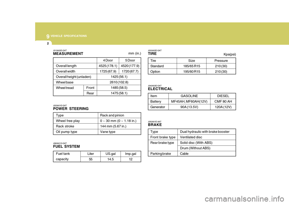
J010A02E-GAT MEASUREMENT
1425 (56.1)
2610 (102.8)
1485 (58.5) 1475 (58.1)
Overall lengthOverall width Overall height (unladen)Wheel base Wheel tread
Front
Rear
Type Wheel free playRack stroke Oil pump type Rack and pinion0 ~ 30 mm (0 ~ 1.18 in.) 144 mm (5.67 in.)Vane type
J060A01S-GAT FUEL SYSTEM
J020A01E-GATPOWER STEERING J030A02E-GATTIRE
Size
185/65 R15 195/60 R15
Tire Standard Option
J050A01E-AAT BRAKE Dual hydraulic with brake booster Ventilated disc Solid disc (With ABS) Drum (Without ABS)Cable
TypeFront brake type Rear brake type Parking brake
Item Battery Generator
J040A03E-GAT ELECTRICAL
GASOLINE
MF45AH, MF60AH(12V) 90A (13.5V)
mm (in.)
Fuel tank capacityLiter
55 US.gal
14.5 Imp.gal
12
DIESEL
CMF 80 AH 120A (12V)
4 Door
4525 (178.1)
1725 (67.9) 5 Door
4520 (177.9)
1720 (67.7)Pressure210 (30) 210 (30)
Kpa(psi)
Page 274 of 277
10
INDEX
3
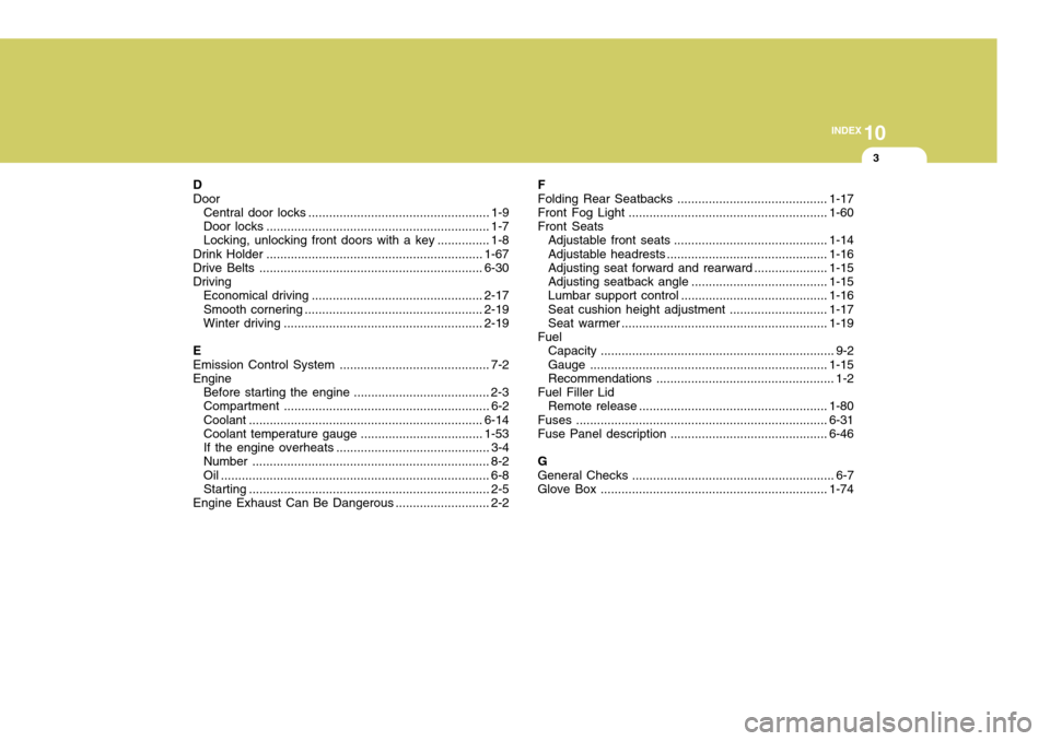
D Door Central door locks .................................................... 1-9
Door locks ................................................................ 1-7
Locking, unlocking front doors with a key ............... 1-8
Drink Holder .............................................................. 1-67
Drive Belts ................................................................ 6-30
Driving Economical driving ................................................. 2-17
Smooth cornering ................................................... 2-19
Winter driving ......................................................... 2-19
EEmission Control Syst em ........................................... 7-2
Engine
Before starting the engine ....................................... 2-3
Compartment ........................................................... 6-2
Coolant ................................................................... 6-14
Coolant temperature gauge ................................... 1-53
If the engine overheats ............................................ 3-4
Number .................................................................... 8-2
Oil ............................................................................. 6-8
Starting ..................................................................... 2-5
Engine Exhaust Can Be Dangerous ........................... 2-2F
Folding Rear Seatbacks .
.......................................... 1-17
Front Fog Light ......................................................... 1-60
Front Seats Adjustable front seats ............................................ 1-14
Adjustable headrest s .............................................. 1-16
Adjusting seat forward and rear ward..................... 1-15
Adjusting seatback angle .......................................1-15
Lumbar support control .................. ........................ 1-16
Seat cushion height adjustment............................ 1-17
Seat warmer ........................................................... 1-19
Fuel Capacity ................................................................... 9-2
Gauge .................................................................... 1-15
Recommendations ................................................... 1-2
Fuel Filler Lid Remote release ...................................................... 1-80
Fuses ........................................................................ 6-31
Fuse Panel description ............................................. 6-46
GGeneral Checks .......................................................... 6-7
Glove Box ................................................................. 1-74