Hyundai Elantra 2010 Owner's Manual
Manufacturer: HYUNDAI, Model Year: 2010, Model line: Elantra, Model: Hyundai Elantra 2010Pages: 348, PDF Size: 5.78 MB
Page 311 of 348
Maintenance
44
7
Snow tires
If you equip your car with snow tires,
they should be the same size and
have the same load capacity as the
original tires. Snow tires should be
installed on all four wheels; other-
wise, poor handling may result.
Snow tires should carry 4 psi (28
kPa) more air pressure than the
pressure recommended for the stan-
dard tires on the tire label on the dri-
ver's side of the center pillar, or up to
the maximum pressure shown on the
tire sidewall, whichever is less.
Do not drive faster than 75 mph (120
km/h) when your car is equipped with
snow tires.
Tire chains
Tire chains, if necessary, should be
installed on the drive wheels (front
wheels).
Be sure that the chains are installed
in accordance with the manufactur-
er's instructions.
To minimize tire and chain wear, do
not continue to use tire chains when
they are no longer needed.
WARNING - Snow or ice
When driving on roads cov- ered with snow or ice, drive at
less than 20 mph (30 km/h).
Use the SAE “S” class or wire chains.
If you have noise caused by chains contacting the body,
retighten the chain to avoid
contact with the vehicle body.
To prevent body damage, retighten the chains after driv-
ing 0.3~0.6 miles.
Do not use tire chains on vehicles equipped with alu-
minum wheels. In unavoid-
able circumstance, use a wire
type chain.
Use wire chains less than 15mm to prevent damage to
the chain’s connection.CAUTION
If you hear noise caused by chains contacting the body,retighten the chain to avoidcontact with the vehicle body.
To prevent body damage, retighten the chains after driv-ing 0.3 ~ 0.6 miles (0.5 ~ 1.0 km).
Page 312 of 348
745
Maintenance
FUSES
A vehicle’s electrical system is protected
from electrical overload damage by
fuses.This vehicle has 2 fuse panels, one locat-
ed in the driver’s side panel bolster, the
other in the engine compartment near
the battery.
If any of your vehicle’s lights, acces-
sories, or controls do not work, check the
appropriate circuit fuse. If a fuse has
blown, the element inside the fuse will be
melted.
If the electrical system does not work,
first check the driver’s side fuse panel.
Always replace a blown fuse with one of
the same rating.
If the replacement fuse blows, this indi-
cates an electrical problem. Avoid using
the system involved and immediately
consult an authorized Hyundai dealer.
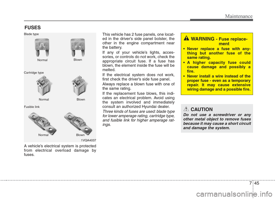
Three kinds of fuses are used: blade type
for lower amperage rating, cartridge type, and fusible link for higher amperage rat-ings.
1VQA4037
Normal
Normal
Blade type
Cartridge type
Fusible link Blown
Blown
Normal Blown
WARNING - Fuse replace- ment
Never replace a fuse with any-
thing but another fuse of the
same rating.
A higher capacity fuse could cause damage and possibly a
fire.
Never install a wire instead of the proper fuse - even as a temporary
repair. It may cause extensive
wiring damage and a possible fire.
CAUTION
Do not use a screwdriver or any
other metal object to remove fuses because it may cause a short circuitand damage the system.
Page 313 of 348
Maintenance
46
7
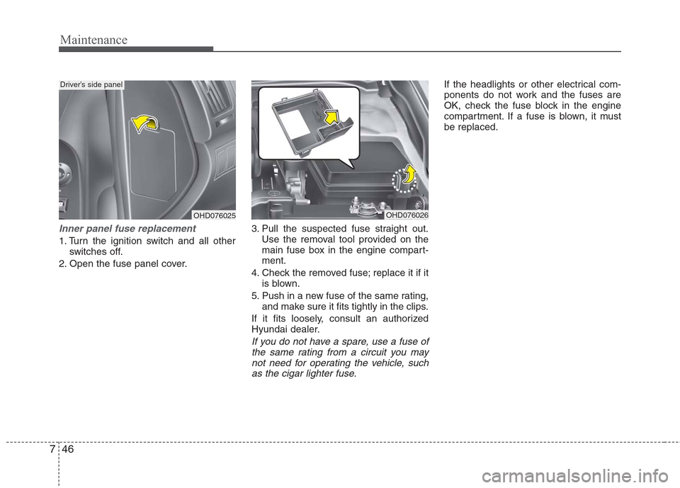
Inner panel fuse replacement
1. Turn the ignition switch and all other
switches off.
2. Open the fuse panel cover. 3. Pull the suspected fuse straight out.
Use the removal tool provided on the
main fuse box in the engine compart-
ment.
4. Check the removed fuse; replace it if it is blown.
5. Push in a new fuse of the same rating, and make sure it fits tightly in the clips.
If it fits loosely, consult an authorized
Hyundai dealer.
If you do not have a spare, use a fuse of the same rating from a circuit you may not need for operating the vehicle, suchas the cigar lighter fuse.
If the headlights or other electrical com-
ponents do not work and the fuses are
OK, check the fuse block in the engine
compartment. If a fuse is blown, it must
be replaced.
OHD076025
Driver’s side panel
OHD076026
Page 314 of 348
747
Maintenance
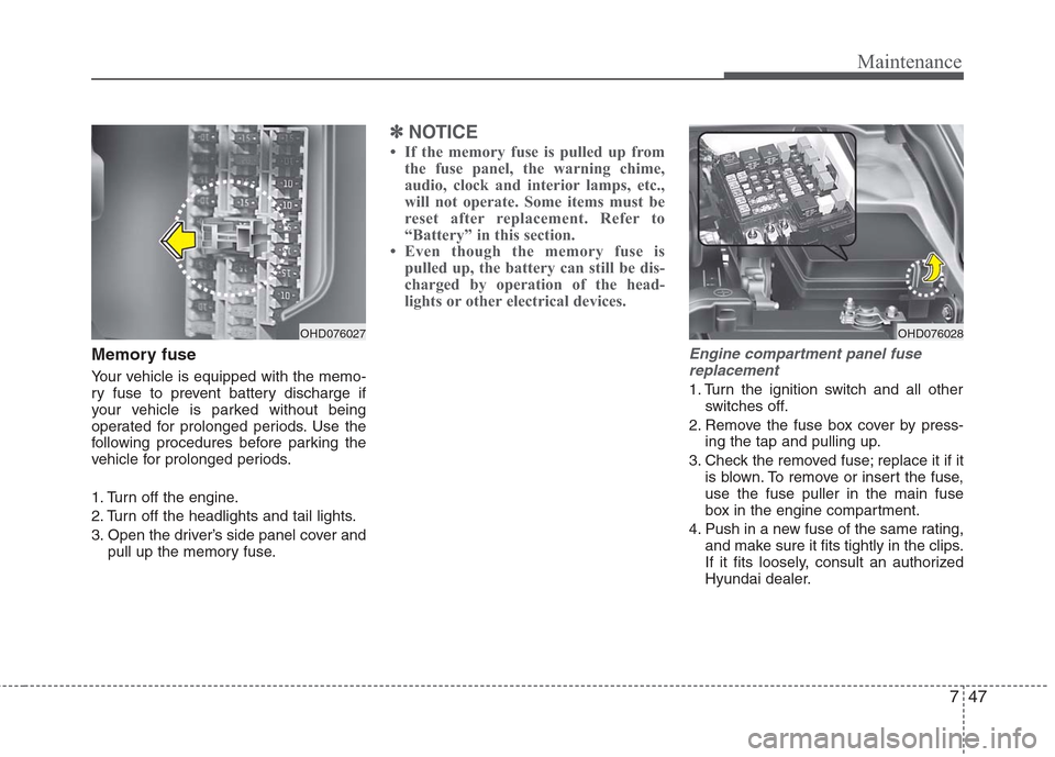
Memory fuse
Your vehicle is equipped with the memo-
ry fuse to prevent battery discharge if
your vehicle is parked without being
operated for prolonged periods. Use the
following procedures before parking the
vehicle for prolonged periods.
1. Turn off the engine.
2. Turn off the headlights and tail lights.
3. Open the driver’s side panel cover andpull up the memory fuse.
✽ ✽NOTICE
• If the memory fuse is pulled up from
the fuse panel, the warning chime,
audio, clock and interior lamps, etc.,
will not operate. Some items must be
reset after replacement. Refer to
“Battery” in this section.
• Even though the memory fuse is pulled up, the battery can still be dis-
charged by operation of the head-
lights or other electrical devices.
Engine compartment panel fuse
replacement
1. Turn the ignition switch and all other switches off.
2. Remove the fuse box cover by press- ing the tap and pulling up.
3. Check the removed fuse; replace it if it is blown. To remove or insert the fuse,
use the fuse puller in the main fuse
box in the engine compartment.
4. Push in a new fuse of the same rating, and make sure it fits tightly in the clips.
If it fits loosely, consult an authorized
Hyundai dealer.
OHD076027
OHD076028
Page 315 of 348
Maintenance
48
7
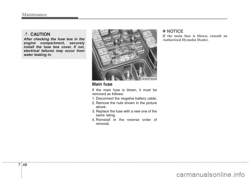
Main fuse
If the main fuse is blown, it must be
removed as follows:
1. Disconnect the negative battery cable.
2. Remove the nuts shown in the picture
above.
3. Replace the fuse with a new one of the same rating.
4. Reinstall in the reverse order of removal.
✽ ✽NOTICE
If the main fuse is blown, consult an
Authorized Hyundai Dealer.CAUTION
After checking the fuse box in the
engine compartment, securelyinstall the fuse box cover. If not,electrical failures may occur fromwater leaking in.
OHD076030
Page 316 of 348
749
Maintenance
✽
✽NOTICE
Not all fuse panel descriptions in this
manual may be applicable to your vehi-
cle. It is accurate at the time of printing.
When you inspect the fuse box on your
vehicle, refer to the fuse box label.
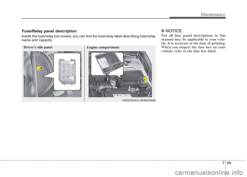
Engine compartment
OHD076031L/OHD076032
Fuse/Relay panel description
Inside the fuse/relay box covers, you can find the fuse/relay label describing fuse/relay
name and capacity.
Driver’s side panel
Page 317 of 348

Maintenance
50
7
Driver's side fuse panel
Description Fuse rating Protected component
START 10A Ignition lock switch, Antitheft alarm, Transaxle range switch
A/CON SW 10A A/C control module
HTD MIRR 10A Outside heated mirror motor
SEAT HTR 15A Seat warmer switch
A/CON 10A Blower relay, A/C control module, Sunroof control module
HEAD LAMP 10A Head lamp relay
FR WIPER 25A Front wiper relay
RR WIPER 15A (Spare)
DRL 15A Daytime running lamp unit
WCS 10A Occupant classification sensor
P/WDW DR 25A Power window main switch, Rear power window switch(LH)
CLOCK 10A Digital clock, Audio
C/LIGHTER 15A Power outlet
DR LOCK 20A Sunroof control module, Door unlock/lock relay
DEICER 15A -
STOP 15A Stop lamp switch
ROOM LP 15A Trunk room lamp, Dome lamp, Map lamp, Digital clock, Home link
AUDIO 15A Audio
T/LID 15A Trunk lid relay
AMP 25A Amplifier
SAFETY P/WDW 25A Safety power window module
P/WDW ASS 25A Front & rear power window switch(RH), Power window main switch
P/OUTLET 15A Power outlet
T/SIG 10A Hazard switch
A/BAG IND 10A Airbag indicator(instrument cluster)
Page 318 of 348
751
Maintenance
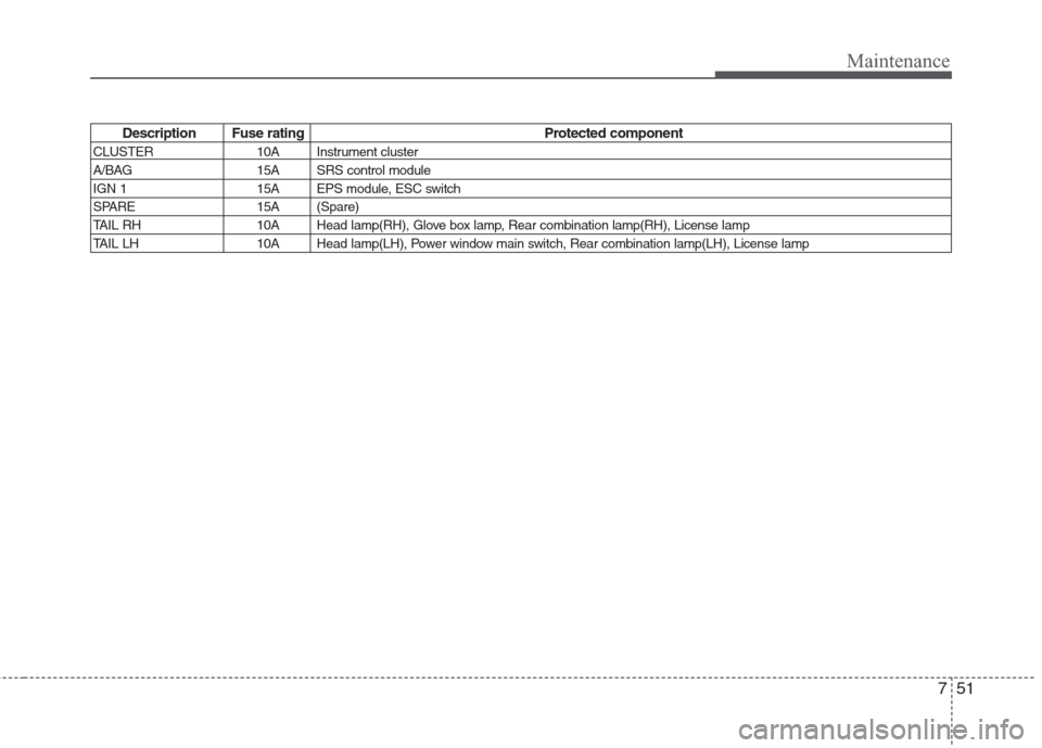
Description Fuse rating Protected component
CLUSTER 10A Instrument cluster
A/BAG 15A SRS control module
IGN 1 15A EPS module, ESC switch
SPARE 15A (Spare)
TAIL RH 10A Head lamp(RH), Glove box lamp, Rear combination lamp(RH), License lamp
TAIL LH 10A Head lamp(LH), Power window main switch, Rear combination lamp(LH), License lamp
Page 319 of 348

Maintenance
52
7
Engine compartment
Description Fuse rating Protected component
ALTERNATOR 150A Generator
EPS 80A EPS control module
ABS.2 20A ESC control module, ABS control module, Multi purpose check connector
ABS.1 40A ESC control module, ABS control module, Multi purpose check connector
B+.1 50A Instrument panel junction box
Fusible link RR HTD 40A Instrument panel junction box BLOWER 40A Blower relay
C/FAN 40A Condenser fan #1, 2 relay
B+.2 50A Instrument panel junction box
IGN.2 40A Ignition switch, Start relay
IGN.1 30A Ignition switch
ECU 30A Main relay, ECM
SPARE.1 20A (Spare)
FR FOG 15A Front fog lamp relay
A/CON 10A A/C relay
Fuse HAZARD 15A Hazard switch, Hazard relay F/PUMP 15A Fuel pump relay
INJ 15A A/C relay, Fuel pump relay, Injector #1,2,3,4, ECM, Idle speed actuator etc.
SNSR.2 10A Pulse generator 'A', 'B’, Stop lamp switch, Vehicle speed sensor etc.
HORN 15A Horn relay
Page 320 of 348
753
Maintenance
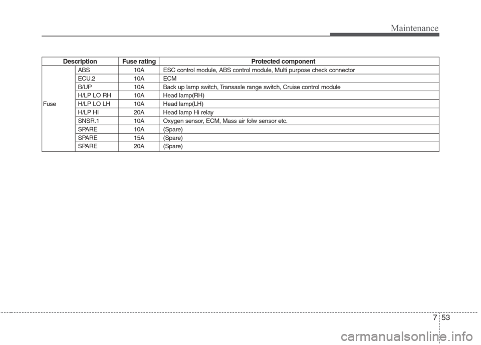
Description Fuse rating Protected component
ABS 10A ESC control module, ABS control module, Multi purpose check connector
ECU.2 10A ECM
B/UP 10A Back up lamp switch, Transaxle range switch, Cruise control module
H/LP LO RH 10A Head lamp(RH)
Fuse H/LP LO LH 10A Head lamp(LH) H/LP HI 20A Head lamp Hi relay
SNSR.1 10A Oxygen sensor, ECM, Mass air folw sensor etc.
SPARE 10A (Spare)
SPARE 15A (Spare)
SPARE 20A (Spare)