head light control Hyundai Elantra 2013 Owner's Manual
[x] Cancel search | Manufacturer: HYUNDAI, Model Year: 2013, Model line: Elantra, Model: Hyundai Elantra 2013Pages: 383, PDF Size: 8.94 MB
Page 140 of 383
Features of your vehicle
62 4
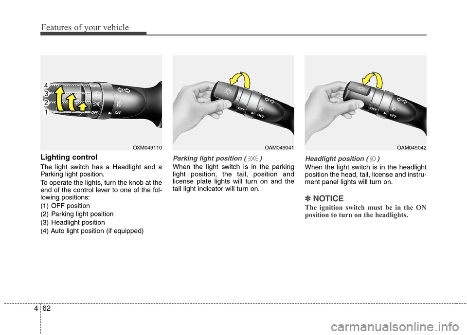
Lighting control
The light switch has a Headlight and a
Parking light position.
To operate the lights, turn the knob at the
end of the control lever to one of the fol-
lowing positions:
(1) OFF position
(2) Parking light position
(3) Headlight position
(4) Auto light position (if equipped)
Parking light position ( )
When the light switch is in the parking
light position, the tail, position and
license plate lights will turn on and the
tail light indicator will turn on.
Headlight position ( )
When the light switch is in the headlight
position the head, tail, license and instru-
ment panel lights will turn on.
✽ ✽
NOTICE
The ignition switch must be in the ON
position to turn on the headlights.
OXM049110OAM049041OAM049042
Page 141 of 383
463
Features of your vehicle
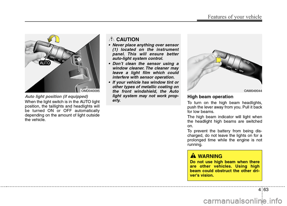
Auto light position (if equipped)
When the light switch is in the AUTO light
position, the taillights and headlights will
be turned ON or OFF automatically
depending on the amount of light outside
the vehicle.
High beam operation
To turn on the high beam headlights,
push the lever away from you. Pull it back
for low beams.
The high beam indicator will light when
the headlight high beams are switched
on.
To prevent the battery from being dis-
charged, do not leave the lights on for a
prolonged time while the engine is not
running.
CAUTION
Never place anything over sensor
(1) located on the instrument
panel. This will ensure better
auto-light system control.
Don’t clean the sensor using a
window cleaner. The cleaner may
leave a light film which could
interfere with sensor operation.
If your vehicle has window tint or
other types of metallic coating on
the front windshield, the Auto
light system may not work prop-
erly.
OMD040095OAM049044
WARNING
Do not use high beam when there
are other vehicles. Using high
beam could obstruct the other dri-
ver's vision.
Page 231 of 383
Driving your vehicle
24 5
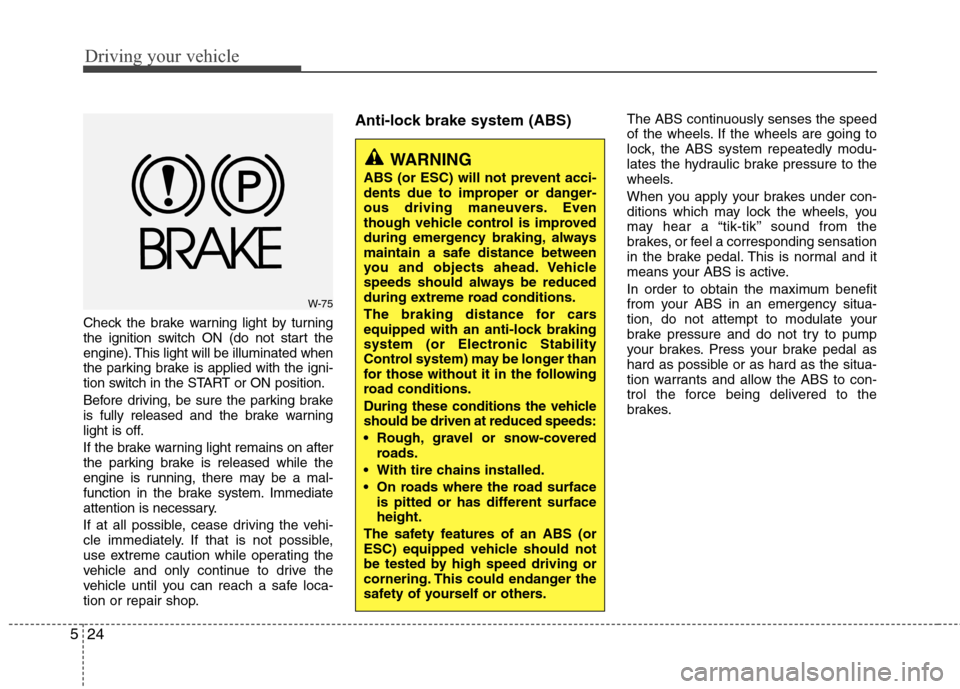
Check the brake warning light by turning
the ignition switch ON (do not start the
engine). This light will be illuminated when
the parking brake is applied with the igni-
tion switch in the START or ON position.
Before driving, be sure the parking brake
is fully released and the brake warning
light is off.
If the brake warning light remains on after
the parking brake is released while the
engine is running, there may be a mal-
function in the brake system. Immediate
attention is necessary.
If at all possible, cease driving the vehi-
cle immediately. If that is not possible,
use extreme caution while operating the
vehicle and only continue to drive the
vehicle until you can reach a safe loca-
tion or repair shop.
Anti-lock brake system (ABS)The ABS continuously senses the speed
of the wheels. If the wheels are going to
lock, the ABS system repeatedly modu-
lates the hydraulic brake pressure to the
wheels.
When you apply your brakes under con-
ditions which may lock the wheels, you
may hear a “tik-tik’’ sound from the
brakes, or feel a corresponding sensation
in the brake pedal. This is normal and it
means your ABS is active.
In order to obtain the maximum benefit
from your ABS in an emergency situa-
tion, do not attempt to modulate your
brake pressure and do not try to pump
your brakes. Press your brake pedal as
hard as possible or as hard as the situa-
tion warrants and allow the ABS to con-
trol the force being delivered to the
brakes.
WARNING
ABS (or ESC) will not prevent acci-
dents due to improper or danger-
ous driving maneuvers. Even
though vehicle control is improved
during emergency braking, always
maintain a safe distance between
you and objects ahead. Vehicle
speeds should always be reduced
during extreme road conditions.
The braking distance for cars
equipped with an anti-lock braking
system (or Electronic Stability
Control system) may be longer than
for those without it in the following
road conditions.
During these conditions the vehicle
should be driven at reduced speeds:
Rough, gravel or snow-covered
roads.
With tire chains installed.
On roads where the road surface
is pitted or has different surface
height.
The safety features of an ABS (or
ESC) equipped vehicle should not
be tested by high speed driving or
cornering. This could endanger the
safety of yourself or others.
W-75
Page 236 of 383
529
Driving your vehicle
After parking the vehicle, check to be
sure the parking brake is not engaged
and that the parking brake indicator
light is out before driving away.
Driving through water may get the
brakes wet. They can also get wet when
the car is washed. Wet brakes can be
dangerous! Your car will not stop as
quickly if the brakes are wet. Wet brakes
may cause the car to pull to one side.
To dry the brakes, apply the brakes light-
ly until the braking action returns to nor-
mal, taking care to keep the car under
control at all times. If the braking action
does not return to normal, stop as soon
as it is safe to do so and call an author-
ized HYUNDAI dealer for assistance.
Do not coast down hills with the car out
of gear. This is extremely hazardous.
Keep the car in gear at all times, use
the brakes to slow down, then shift to a
lower gear so that engine braking will
help you maintain a safe speed.
Do not "ride" the brake pedal. Resting
your foot on the brake pedal while driv-
ing can be dangerous because it can
result in the brakes overheating and los-
ing their effectiveness. It also increases
the wear of the brake components. If a tire goes flat while you are driving,
apply the brakes gently and keep the
car pointed straight ahead while you
slow down. When you are moving slow-
ly enough for it to be safe to do so, pull
off the road and stop in a safe place.
If your vehicle is equipped with an auto-
matic transaxle, don't let your vehicle
creep forward. To avoid creeping for-
ward, keep your foot firmly on the brake
pedal when the vehicle is stopped.
Use caution when parking on a hill.
Firmly engage the parking brake and
place the shift lever in P (automatic
transaxle) or in first or reverse gear
(manual transaxle). If your vehicle is
facing downhill, turn the front wheels
into the curb to help keep the vehicle
from rolling. If your vehicle is facing
uphill, turn the front wheels away from
the curb to help keep the vehicle from
rolling. If there is no curb or if it is
required by other conditions to keep
the vehicle from rolling, block the
wheels. Under some conditions your parking
brake can freeze in the engaged posi-
tion. This is most likely to happen when
there is an accumulation of snow or ice
around or near the rear brakes or if the
brakes are wet. If there is a risk that the
parking brake may freeze, apply it only
temporarily while you put the gear
selector lever in P (automatic
transaxle) or in first or reverse gear
(manual transaxle) and block the rear
wheels so the vehicle cannot roll. Then
release the parking brake.
Do not hold the vehicle on the upgrade
with the accelerator pedal. This can
cause the transaxle to overheat.
Always use the brake pedal or parking
brake.
Page 237 of 383
Driving your vehicle
30 5
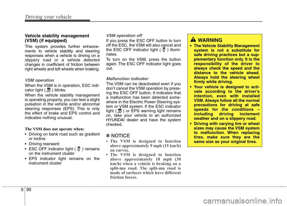
Vehicle stability management
(VSM) (if equipped)
This system provides further enhance-
ments to vehicle stability and steering
responses when a vehicle is driving on a
slippery road or a vehicle detected
changes in coefficient of friction between
right wheels and left wheels when braking.
VSM operation
When the VSM is in operation, ESC indi-
cator light ( ) blinks.
When the vehicle stability management
is operating properly, you can feel a slight
pulsation in the vehicle and/or abnormal
steering responses (EPS). This is only
the effect of brake and EPS control and
indicates nothing unusual.
The VSM does not operate when:
Driving on bank road such as gradient
or incline
Driving rearward
ESC OFF indicator light ( ) remains
on the instrument cluster
EPS indicator light remains on the
instrument cluster
VSM operation off
If you press the ESC OFF button to turn
off the ESC, the VSM will also cancel and
the ESC OFF indicator light ( ) illumi-
nates.
To turn on the VSM, press the button
again. The ESC OFF indicator light goes
out.
Malfunction indicator
The VSM can be deactivated even if you
don’t cancel the VSM operation by press-
ing the ESC OFF button. It indicates that
a malfunction has been detected some-
where in the Electric Power Steering sys-
tem or VSM system. If the ESC indicator
light ( ) or EPS warning light remains
on, take your vehicle to an authorized
HYUNDAI dealer and have the system
checked.
✽ ✽
NOTICE
• The VSM is designed to function
above approximately 9 mph (15 km/h)
on curves.
• The VSM is designed to function
above approximately 18 mph (30
km/h) when a vehicle is braking on a
split-mu road. The split-mu road is
made of surfaces which have different
friction forces.
WARNING
The Vehicle Stability Management
system is not a substitute for
safe driving practices but a sup-
plementary function only. It is the
responsibility of the driver to
always check the speed and the
distance to the vehicle ahead.
Always hold the steering wheel
firmly while driving.
Your vehicle is designed to acti-
vate according to the driver’s
intention, even with installed
VSM. Always follow all the normal
precautions for driving at safe
speeds for the conditions –
including driving inclement
weather and on a slippery road.
Driving with varying tire or wheel
sizes may cause the VSM system
to malfunction. When replacing
tires, make sure they are the
same size as your original tires.
Page 293 of 383
75
Maintenance
While operating your vehicle:
Note any changes in the sound of the
exhaust or any smell of exhaust fumes
in the vehicle.
Check for vibrations in the steering
wheel. Notice any increased steering
effort or looseness in the steering
wheel, or change in its straight-ahead
position.
Notice if your vehicle constantly turns
slightly or “pulls” to one side when trav-
eling on smooth, level road.
When stopping, listen and check for
unusual sounds, pulling to one side,
increased brake pedal travel or “hard-
to-push” brake pedal.
If any slipping or changes in the oper-
ation of your transaxle occurs, check
the transaxle fluid level.
Check automatic transaxle P (Park)
function.
Check parking brake.
Check for fluid leaks under your vehicle
(water dripping from the air condition-
ing system during or after use is nor-
mal).
At least monthly:
Check coolant level in the engine
coolant reservoir.
Check the operation of all exterior
lights, including the stoplights, turn sig-
nals and hazard warning flashers.
Check the inflation pressures of all
tires including the spare.
At least twice a year
(i.e., every Spring and Fall):
Check radiator, heater and air condi-
tioning hoses for leaks or damage.
Check windshield washer spray and
wiper operation. Clean wiper blades
with clean cloth dampened with wash-
er fluid.
Check headlight alignment.
Check muffler, exhaust pipes, shields
and clamps.
Check the lap/shoulder belts for wear
and function.
Check for worn tires and loose wheel
lug nuts.
At least once a year:
Clean body and door drain holes.
Lubricate door hinges and checks, and
hood hinges.
Lubricate door and hood locks and
latches.
Lubricate door rubber weatherstrips.
Check the air conditioning system.
Inspect and lubricate automatic
transaxle linkage and controls.
Clean battery and terminals.
Check the brake fluid level.
Page 329 of 383
741
Maintenance
Compact spare tire replacement
(if equipped)
A compact spare tire has a shorter
tread life than a regular size tire.
Replace it when you can see the
tread wear indicator bars on the tire.
The replacement compact spare tire
should be the same size and design
tire as the one provided with your
new vehicle and should be mounted
on the same compact spare tire
wheel. The compact spare tire is not
designed to be mounted on a regular
size wheel, and the compact spare
tire wheel is not designed for mount-
ing a regular size tire.Wheel replacement
When replacing the metal wheels for
any reason, make sure the new
wheels are equivalent to the original
factory units in diameter, rim width
and offset.Tire traction
Tire traction can be reduced if you
drive on worn tires, tires that are
improperly inflated or on slippery
road surfaces. Tires should be
replaced when tread wear indicators
appear. To reduce the possibility of
losing control, slow down whenever
there is rain, snow or ice on the road.
Tire maintenance
In addition to proper inflation, correct
wheel alignment helps to decrease
tire wear. If you find a tire is worn
unevenly, have your dealer check the
wheel alignment.
When you have new tires installed,
make sure they are balanced. This
will increase vehicle ride comfort and
tire life. Additionally, a tire should
always be rebalanced if it is removed
from the wheel.
WARNING
A wheel that is not the correct
size may adversely affect wheel
and bearing life, braking and
stopping abilities, handling char-
acteristics, ground clearance,
body-to-tire clearance, snow
chain clearance, speedometer
and odometer calibration, head-
light aim and bumper height.
Page 342 of 383
Maintenance
54 7
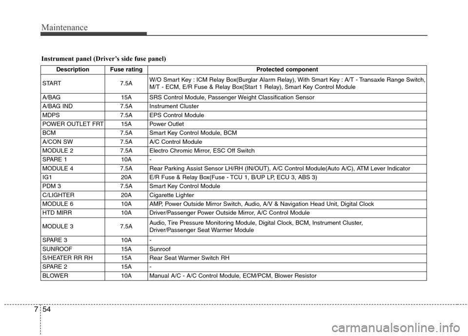
Instrument panel (Driver’s side fuse panel)
Description Fuse rating Protected component
START 7.5AW/O Smart Key : ICM Relay Box(Burglar Alarm Relay), With Smart Key : A/T - Transaxle Range Switch,
M/T - ECM, E/R Fuse & Relay Box(Start 1 Relay), Smart Key Control Module
A/BAG 15A SRS Control Module, Passenger Weight Classification Sensor
A/BAG IND 7.5A Instrument Cluster
MDPS 7.5A EPS Control Module
POWER OUTLET FRT 15A Power Outlet
BCM 7.5A Smart Key Control Module, BCM
A/CON SW 7.5A A/C Control Module
MODULE 2 7.5A Electro Chromic Mirror, ESC Off Switch
SPARE 1 10A -
MODULE 4 7.5A Rear Parking Assist Sensor LH/RH (IN/OUT), A/C Control Module(Auto A/C), ATM Lever Indicator
IG1 20A E/R Fuse & Relay Box(Fuse - TCU 1, B/UP LP, ECU 3, ABS 3)
PDM 3 7.5A Smart Key Control Module
C/LIGHTER 20A Cigarette Lighter
MODULE 6 10A AMP, Power Outside Mirror Switch, Audio, A/V & Navigation Head Unit, Digital Clock
HTD MIRR 10A Driver/Passenger Power Outside Mirror, A/C Control Module
MODULE 3 7.5AAudio, Tire Pressure Monitoring Module, Digital Clock, BCM, Instrument Cluster,
Driver/Passenger Seat Warmer Module
SPARE 3 10A -
SUNROOF 15A Sunroof
S/HEATER RR RH 15A Rear Seat Warmer Switch RH
SPARE 2 15A -
BLOWER 10A Manual A/C - A/C Control Module, ECM/PCM, Blower Resistor
Page 343 of 383
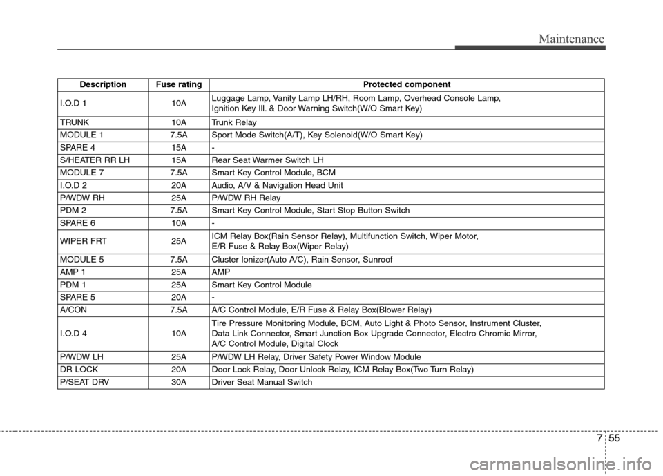
755
Maintenance
Description Fuse rating Protected component
I.O.D 1 10ALuggage Lamp, Vanity Lamp LH/RH, Room Lamp, Overhead Console Lamp,
Ignition Key Ill. & Door Warning Switch(W/O Smart Key)
TRUNK 10A Trunk Relay
MODULE 1 7.5A Sport Mode Switch(A/T), Key Solenoid(W/O Smart Key)
SPARE 4 15A -
S/HEATER RR LH 15A Rear Seat Warmer Switch LH
MODULE 7 7.5A Smart Key Control Module, BCM
I.O.D 2 20A Audio, A/V & Navigation Head Unit
P/WDW RH 25A P/WDW RH Relay
PDM 2 7.5A Smart Key Control Module, Start Stop Button Switch
SPARE 6 10A -
WIPER FRT 25AICM Relay Box(Rain Sensor Relay), Multifunction Switch, Wiper Motor,
E/R Fuse & Relay Box(Wiper Relay)
MODULE 5 7.5A Cluster Ionizer(Auto A/C), Rain Sensor, Sunroof
AMP 1 25A AMP
PDM 1 25A Smart Key Control Module
SPARE 5 20A -
A/CON 7.5A A/C Control Module, E/R Fuse & Relay Box(Blower Relay)
I.O.D 4 10ATire Pressure Monitoring Module, BCM, Auto Light & Photo Sensor, Instrument Cluster,
Data Link Connector, Smart Junction Box Upgrade Connector, Electro Chromic Mirror,
A/C Control Module, Digital Clock
P/WDW LH 25A P/WDW LH Relay, Driver Safety Power Window Module
DR LOCK 20A Door Lock Relay, Door Unlock Relay, ICM Relay Box(Two Turn Relay)
P/SEAT DRV 30A Driver Seat Manual Switch