fuel Hyundai Elantra 2020 User Guide
[x] Cancel search | Manufacturer: HYUNDAI, Model Year: 2020, Model line: Elantra, Model: Hyundai Elantra 2020Pages: 535, PDF Size: 16.8 MB
Page 133 of 535
3-49
Convenient features of your vehicle
3
Information
• The Smart Trunk function will notwork if any of the following occurs:
- The smart key is close to a radiotransmitter such as a radio station
or an airport which can interfere
with normal operation of the
transmitter.
- The smart key is near a mobile two way radio system or a cellular
phone.
- Another vehicle's smart key is being operated close to your vehi-
cle.
• The detecting range may decrease or increase when :
- One side of the tire is raised toreplace a tire or to inspect the vehi-
cle.
- The vehicle is parked on a slope or unpaved road, etc.
Fuel Filler Door
Opening the fuel filler door
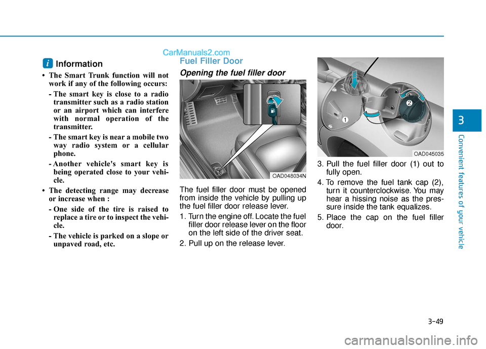
The fuel filler door must be opened
from inside the vehicle by pulling up
the fuel filler door release lever.
1. Turn the engine off. Locate the fuel filler door release lever on the floor
on the left side of the driver seat.
2. Pull up on the release lever. 3. Pull the fuel filler door (1) out to
fully open.
4. To remove the fuel tank cap (2), turn it counterclockwise. You may
hear a hissing noise as the pres-
sure inside the tank equalizes.
5. Place the cap on the fuel filler door.
i
OAD048034N
OAD045035
Page 134 of 535
3-50
Convenient features of your vehicle
Information
If the fuel filler door does not open
because ice has formed around it, tap
lightly or push on the door to break
the ice and release the door. Do not
pry on the door. If necessary, spray
around the door with an approved de-
icer fluid (do not use radiator anti-
freeze) or move the vehicle to a warm
place and allow the ice to melt.
Closing the fuel filler door
1. To install the fuel tank cap, turn itclockwise until it "clicks" one time.
2. Close the fuel filler door until it is latched securely.
Information
• Tighten the cap until it clicks once,otherwise the fuel cap open warn-
ing indicator light will illuminate.
• There may be an intermittent noise near the refueling hole while the
engine is idling if the fuel cap is not
closed securely. This occurs nor-
mally with the OBD system.
• When refueling on unleveled ground, the fuel gauge may not
point to the F position. It is not a
malfunction. If you move your
vehicle to a level ground, the fuel
gauge will move to the full position.
i
i
Gasoline is highly flammable
and explosive. Failure to follow
these guidelines may result in
SERIOUS INJURY or DEATH:
Read and follow all warnings
posted at the gas station.
Before refueling, note the
location of the Emergency
Gasoline Shut-Off, if available,
at the gas station.
Before touching the fuel noz-
zle, you should eliminate the
potential build-up of static
electricity by touching a metal
part of the vehicle, a safe dis-
tance away from the fuel filler
neck, nozzle, or other gas
source, with your bare hand.
Do not use cellular phones
while refueling. Electric cur-
rent and/or electronic interfer-
ence from cellular phones can
potentially ignite fuel vapors
and cause a fire.
WARNING
Page 135 of 535
3-51
Convenient features of your vehicle
3
Use only approved portable
plastic fuel containers designed
to carry and store gasoline.
When refueling, always move
the shift lever to the P (Park)
position, set the parking
brake, and place the ignition
switch to the LOCK/OFF posi-
tion. Sparks produced by
electrical components related
to the engine can ignite fuel
vapors causing a fire.
Do not use matches or a
lighter and do not smoke or
leave a lit cigarette in your
vehicle while at a gas station,
especially during refueling.
Do not over-fill or top-off your
vehicle tank, which can cause
gasoline spillage.
If a fire breaks out during refu-
eling, leave the vicinity of the
vehicle, and immediately con-
tact the manager of the gas
station and then contact the
local fire department. Follow
any safety instructions they
provide.
Do not get back into a vehicle
once you have begun refuel-
ing. You can generate a build-
up of static electricity by
touching, rubbing or sliding
against any item or fabric
capable of producing static
electricity. Static electricity
discharge can ignite fuel
vapors causing a fire. If you
must re-enter the vehicle, you
should once again eliminate
potentially dangerous static
electricity discharge by touch-
ing a metal part of the vehicle,
away from the fuel filler neck,
nozzle or other gasoline
source, with your bare hand.
When using an approved
portable fuel container, be
sure to place the container on
the ground prior to refueling.
Static electricity discharge
from the container can ignite
fuel vapors causing a fire.
Once refueling has begun,
contact between your bare
hand and the vehicle should
be maintained until the filling
is complete.
If pressurized fuel sprays out,
it can cover your clothes or
skin and thus subject you to
the risk of fire and burns.
Always remove the fuel cap
carefully and slowly. If the cap
is venting fuel or if you hear a
hissing sound, wait until the
condition stops before com-
pletely removing the cap.
Always check that the fuel cap
is installed securely to pre-
vent fuel spillage in the event
of an accident.
Page 136 of 535
3-52
Convenient features of your vehicle
Information
Make sure to refuel your vehicle
according to the "Fuel Requirements"
suggested in the Introduction chapter.
Do not spill fuel on the exteriorsurfaces of the vehicle. Any type
of fuel spilled on painted sur-
faces may damage the paint.
If the fuel filler cap requires replacement, use only a genuine
HYUNDAI cap or the equivalent
specified for your vehicle. An
incorrect fuel filler cap can
result in a serious malfunction
of the fuel system or emission
control system.
NOTICE
i
Page 137 of 535
3-53
Convenient features of your vehicle
3
I
IN
N S
ST
T R
R U
U M
M E
EN
N T
T
C
C L
LU
U S
ST
T E
ER
R
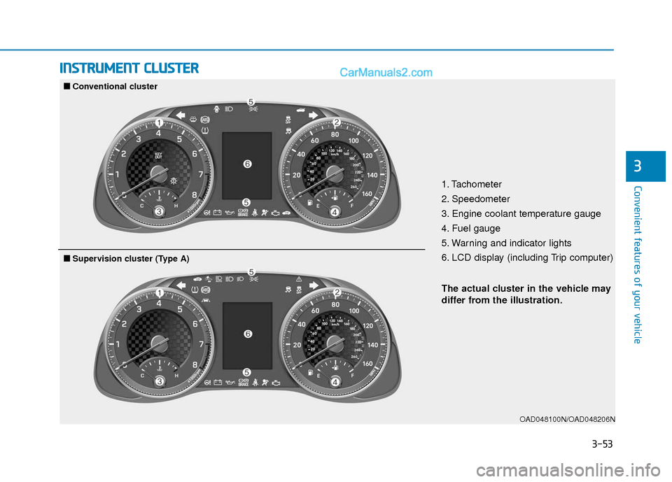
1. Tachometer
2. Speedometer
3. Engine coolant temperature gauge
4. Fuel gauge
5. Warning and indicator lights
6. LCD display (including Trip computer)
OAD048100N/OAD048206N
■
■
Conventional cluster
The actual cluster in the vehicle may
differ from the illustration.
■ ■Supervision cluster (Type A)
Page 138 of 535
3-54
Convenient features of your vehicle
OAD048103N/OAD048102N
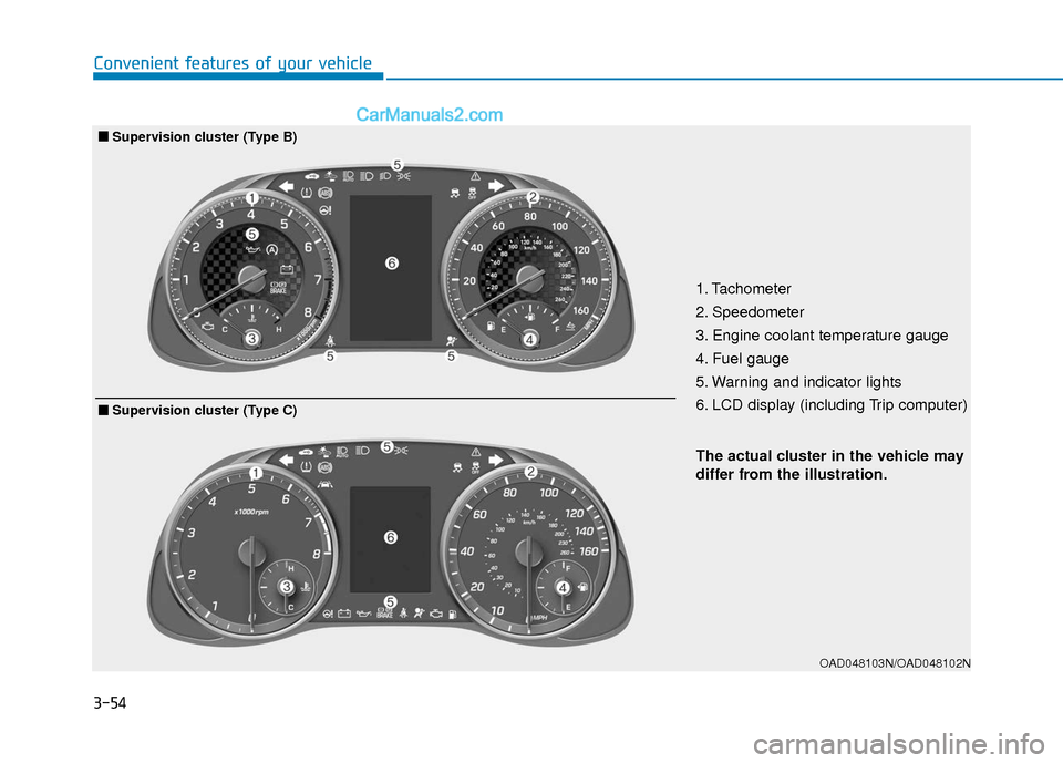
The actual cluster in the vehicle may
differ from the illustration.
■ ■Supervision cluster (Type B)
1. Tachometer
2. Speedometer
3. Engine coolant temperature gauge
4. Fuel gauge
5. Warning and indicator lights
6. LCD display (including Trip computer)
■ ■Supervision cluster (Type C)
Page 141 of 535
3-57
Convenient features of your vehicle
3
If the gauge pointer moves
beyond the normal range area
toward the "H" position, it indi-
cates overheating that may dam-
age the engine.
Do not continue driving with an
overheated engine. If your vehicle
overheats, refer to "If the Engine
Overheats" in chapter 6.
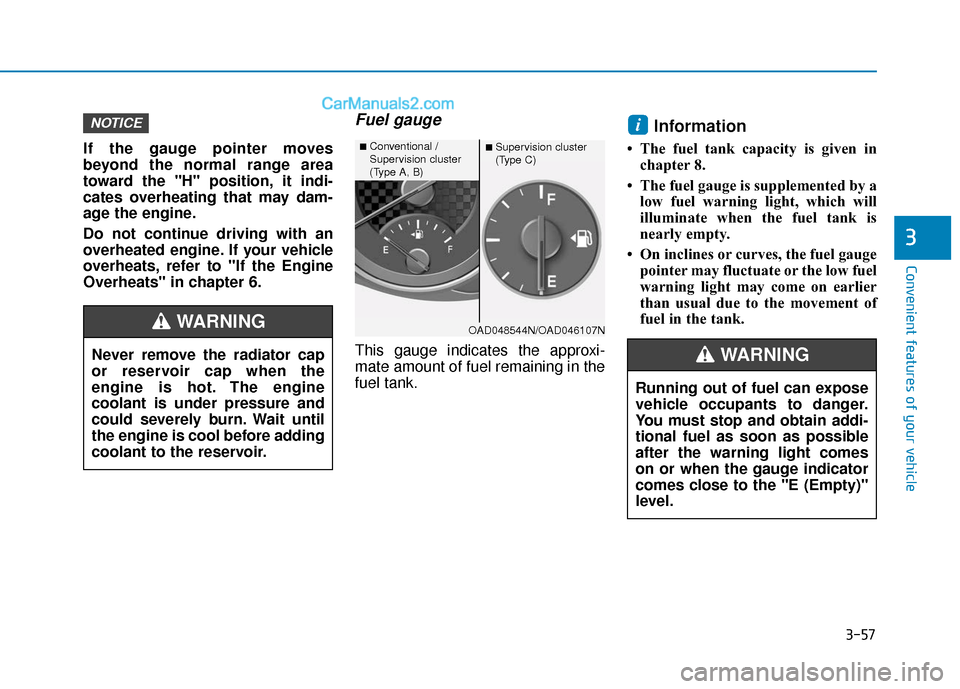
Fuel gauge
This gauge indicates the approxi-
mate amount of fuel remaining in the
fuel tank.
Information
• The fuel tank capacity is given inchapter 8.
• The fuel gauge is supplemented by a low fuel warning light, which will
illuminate when the fuel tank is
nearly empty.
• On inclines or curves, the fuel gauge pointer may fluctuate or the low fuel
warning light may come on earlier
than usual due to the movement of
fuel in the tank.
iNOTICE
OAD048544N/OAD046107N
■Conventional /
Supervision cluster
(Type A, B)■ Supervision cluster
(Type C)
Running out of fuel can expose
vehicle occupants to danger.
You must stop and obtain addi-
tional fuel as soon as possible
after the warning light comes
on or when the gauge indicator
comes close to the "E (Empty)"
level.
WARNINGNever remove the radiator cap
or reservoir cap when the
engine is hot. The engine
coolant is under pressure and
could severely burn. Wait until
the engine is cool before adding
coolant to the reservoir.
WARNING
Page 142 of 535
3-58
Convenient features of your vehicle
Avoid driving with an extremely
low fuel level. Running out of fuel
could cause the engine to misfire,
damaging the catalytic converter.
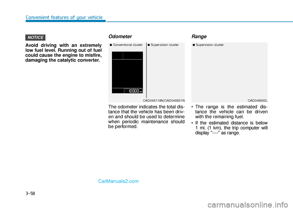
Odometer
The odometer indicates the total dis-
tance that the vehicle has been driv-
en and should be used to determine
when periodic maintenance should
be performed.
Range
The range is the estimated dis- tance the vehicle can be driven
with the remaining fuel.
If the estimated distance is below 1 mi. (1 km), the trip computer will
display "----" as range.
NOTICE
OAD048563L
■Conventional cluster■Supervision cluster■Supervision cluster
OAD045119N/OAD048551N
Page 143 of 535
3-59
Convenient features of your vehicle
3
Information
• If the vehicle is not on level groundor the battery power has been inter-
rupted, the range function may not
operate correctly.
• The range may differ from the actu- al driving distance as it is only an
estimate of the available driving
range for the vehicle and driving
conditions.
• The trip computer may not register additional fuel if less than 1.6 gallon
(6 liters) of fuel are added to the
vehicle.
• The range may vary significantly based on driving conditions, driving
habits, and condition of the vehicle.
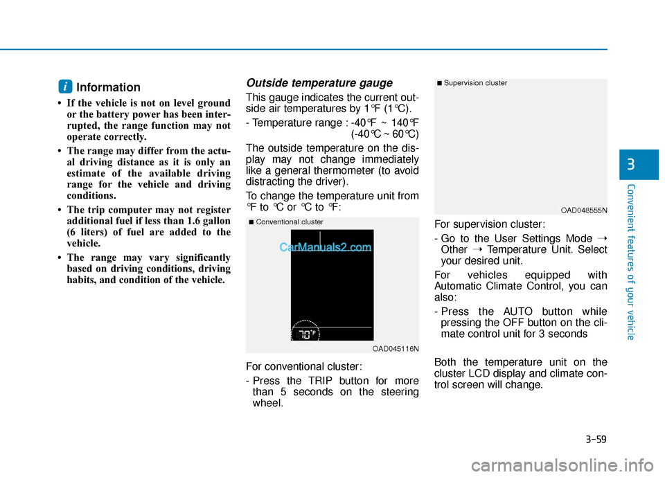
Outside temperature gauge
This gauge indicates the current out-
side air temperatures by 1°F (1°C).
- Temperature range : -40°F ~ 140°F
(-40°C ~ 60°C)
The outside temperature on the dis-
play may not change immediately
like a general thermometer (to avoid
distracting the driver).
To change the temperature unit from
°F to °C or °C to °F:
For conventional cluster:
- Press the TRIP button for more than 5 seconds on the steering
wheel. For supervision cluster:
- Go to the User Settings Mode
➝
Other ➝Temperature Unit. Select
your desired unit.
For vehicles equipped with
Automatic Climate Control, you can
also:
- Press the AUTO button while pressing the OFF button on the cli-
mate control unit for 3 seconds
Both the temperature unit on the
cluster LCD display and climate con-
trol screen will change.i
OAD045116N
■Conventional cluster
■ Supervision cluster
OAD048555N
Page 144 of 535
3-60
Convenient features of your vehicle
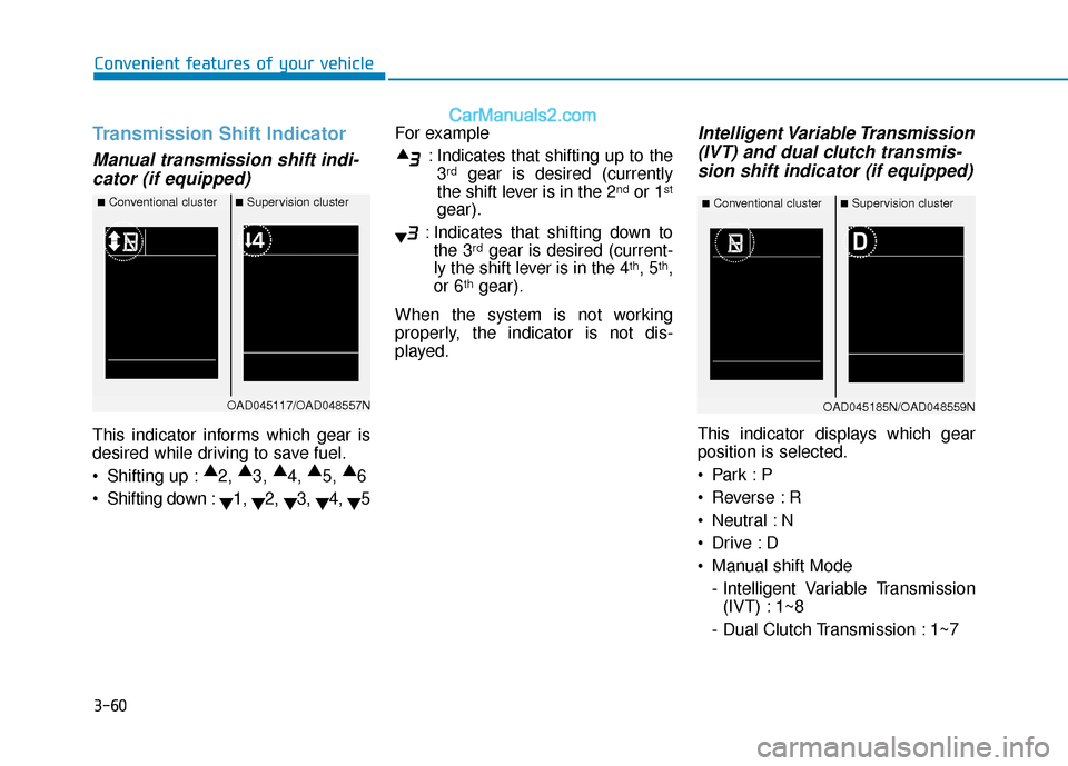
Transmission Shift Indicator
Manual transmission shift indi-cator (if equipped)
This indicator informs which gear is
desired while driving to save fuel.
Shifting up : ▲
2, ▲
3, ▲
4, ▲
5, ▲
6
Shifting down : ▼1,
▼2,
▼3,
▼4,
▼5 For example
: Indicates that shifting up to the3
rdgear is desired (currently
the shift lever is in the 2ndor 1st
gear).
: Indicates that shifting down to the 3
rdgear is desired (current-
ly the shift lever is in the 4th, 5th,
or 6thgear).
When the system is not working
properly, the indicator is not dis-
played.
Intelligent Variable Transmission (IVT) and dual clutch transmis-sion shift indicator (if equipped)
This indicator displays which gear
position is selected.
Reverse : R
Neutral : N
Manual shift Mode
- Intelligent Variable Transmission(IVT) : 1~8
- Dual Clutch Transmission : 1~7
■Conventional cluster■Supervision cluster
OAD045117/OAD048557N
■Conventional cluster■Supervision cluster
OAD045185N/OAD048559N