fuel Hyundai Elantra 2020 Workshop Manual
[x] Cancel search | Manufacturer: HYUNDAI, Model Year: 2020, Model line: Elantra, Model: Hyundai Elantra 2020Pages: 535, PDF Size: 16.8 MB
Page 460 of 535
7-38
Maintenance
T
TI
IR
R E
ES
S
A
A N
N D
D
W
W H
HE
EE
EL
LS
S
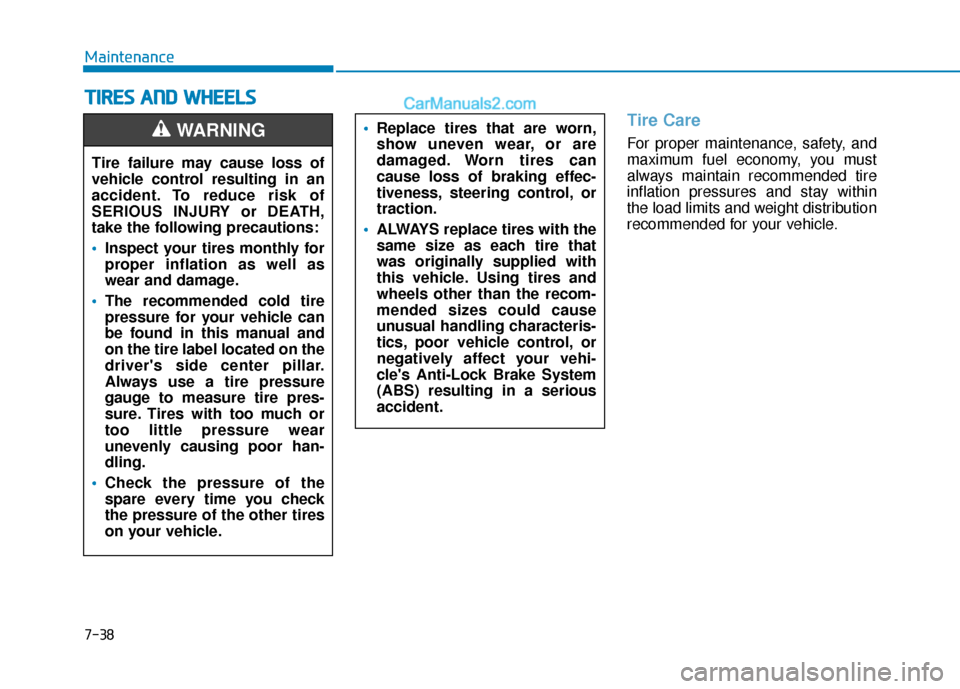
Tire Care
For proper maintenance, safety, and
maximum fuel economy, you must
always maintain recommended tire
inflation pressures and stay within
the load limits and weight distribution
recommended for your vehicle.
Replace tires that are worn,
show uneven wear, or are
damaged. Worn tires can
cause loss of braking effec-
tiveness, steering control, or
traction.
ALWAYS replace tires with the
same size as each tire that
was originally supplied with
this vehicle. Using tires and
wheels other than the recom-
mended sizes could cause
unusual handling characteris-
tics, poor vehicle control, or
negatively affect your vehi-
cle's Anti-Lock Brake System
(ABS) resulting in a serious
accident.
Tire failure may cause loss of
vehicle control resulting in an
accident. To reduce risk of
SERIOUS INJURY or DEATH,
take the following precautions:
Inspect your tires monthly for
proper inflation as well as
wear and damage.
The recommended cold tire
pressure for your vehicle can
be found in this manual and
on the tire label located on the
driver's side center pillar.
Always use a tire pressure
gauge to measure tire pres-
sure. Tires with too much or
too little pressure wear
unevenly causing poor han-
dling.
Check the pressure of the
spare every time you check
the pressure of the other tires
on your vehicle.
WARNING
Page 462 of 535
7-40
Maintenance
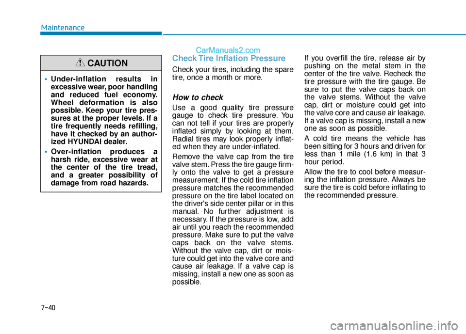
Check Tire Inflation Pressure
Check your tires, including the spare
tire, once a month or more.
How to check
Use a good quality tire pressure
gauge to check tire pressure. You
can not tell if your tires are properly
inflated simply by looking at them.
Radial tires may look properly inflat-
ed when they are under-inflated.
Remove the valve cap from the tire
valve stem. Press the tire gauge firm-
ly onto the valve to get a pressure
measurement. If the cold tire inflation
pressure matches the recommended
pressure on the tire label located on
the driver's side center pillar or in this
manual. No further adjustment is
necessary. If the pressure is low, add
air until you reach the recommended
pressure. Make sure to put the valve
caps back on the valve stems.
Without the valve cap, dirt or mois-
ture could get into the valve core and
cause air leakage. If a valve cap is
missing, install a new one as soon as
possible.If you overfill the tire, release air by
pushing on the metal stem in the
center of the tire valve. Recheck the
tire pressure with the tire gauge. Be
sure to put the valve caps back on
the valve stems. Without the valve
cap, dirt or moisture could get into
the valve core and cause air leakage.
If a valve cap is missing, install a new
one as soon as possible.
A cold tire means the vehicle has
been sitting for 3 hours and driven for
less than 1 mile (1.6 km) in that 3
hour period.
Allow the tire to cool before measur-
ing the inflation pressure. Always be
sure the tire is cold before inflating to
the recommended pressure.
Under-inflation results in
excessive wear, poor handling
and reduced fuel economy.
Wheel deformation is also
possible. Keep your tire pres-
sures at the proper levels. If a
tire frequently needs refilling,
have it checked by an author-
ized HYUNDAI dealer.
Over-inflation produces a
harsh ride, excessive wear at
the center of the tire tread,
and a greater possibility of
damage from road hazards.
CAUTION
Page 470 of 535
7-48
Maintenance
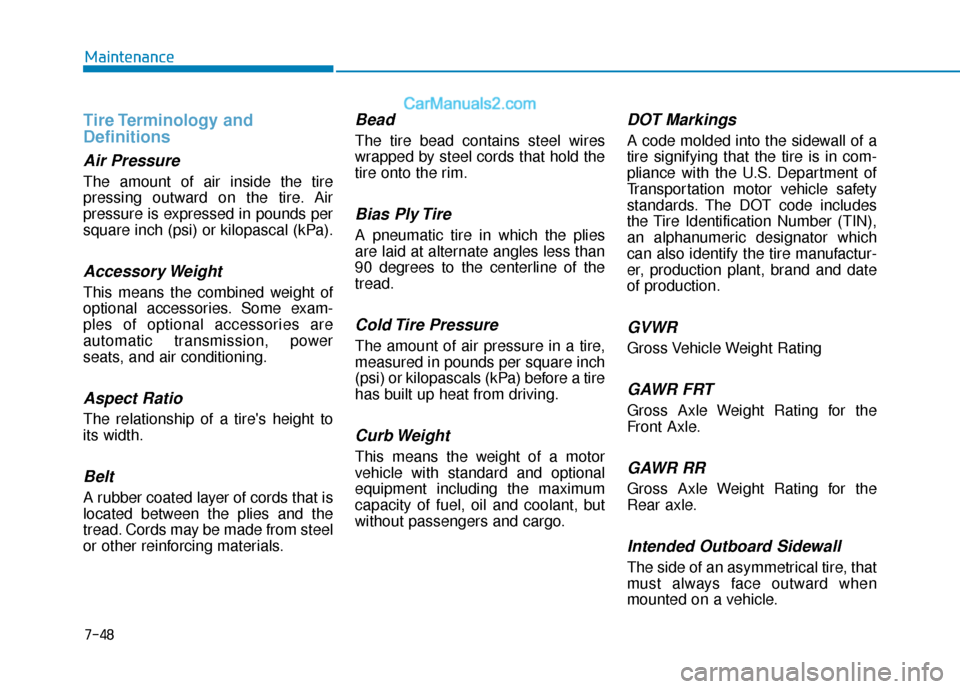
Tire Terminology and
Definitions
Air Pressure
The amount of air inside the tire
pressing outward on the tire. Air
pressure is expressed in pounds per
square inch (psi) or kilopascal (kPa).
Accessory Weight
This means the combined weight of
optional accessories. Some exam-
ples of optional accessories are
automatic transmission, power
seats, and air conditioning.
Aspect Ratio
The relationship of a tire's height to
its width.
Belt
A rubber coated layer of cords that is
located between the plies and the
tread. Cords may be made from steel
or other reinforcing materials.
Bead
The tire bead contains steel wires
wrapped by steel cords that hold the
tire onto the rim.
Bias Ply Tire
A pneumatic tire in which the plies
are laid at alternate angles less than
90 degrees to the centerline of the
tread.
Cold Tire Pressure
The amount of air pressure in a tire,
measured in pounds per square inch
(psi) or kilopascals (kPa) before a tire
has built up heat from driving.
Curb Weight
This means the weight of a motor
vehicle with standard and optional
equipment including the maximum
capacity of fuel, oil and coolant, but
without passengers and cargo.
DOT Markings
A code molded into the sidewall of a
tire signifying that the tire is in com-
pliance with the U.S. Department of
Transportation motor vehicle safety
standards. The DOT code includes
the Tire Identification Number (TIN),
an alphanumeric designator which
can also identify the tire manufactur-
er, production plant, brand and date
of production.
GVWR
Gross Vehicle Weight Rating
GAWR FRT
Gross Axle Weight Rating for the
Front Axle.
GAWR RR
Gross Axle Weight Rating for the
Rear axle.
Intended Outboard Sidewall
The side of an asymmetrical tire, that
must always face outward when
mounted on a vehicle.
Page 485 of 535
7-63
7
Maintenance
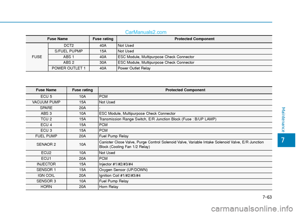
Fuse NameFuse rating Protected Component
FUSE
DCT2 40A Not Used
S/FUEL PUPMP 15A Not Used
ABS 1 40A ESC Module, Multipurpose Check Connector
ABS 2 30A ESC Module, Multipurpose Check Connector
POWER OUTLET 1 40A Power Outlet Relay
Fuse Name Fuse rating Protected Component
ECU 5 10A PCM
VACUUM PUMP 15A Not Used
SPARE 20A -
ABS 3 10A ESC Module, Multipurpose Check Connector
TCU 2 15A Transmission Range Switch, E/R Junction Block (Fuse : B/UP LAMP)
ECU 4 15A PCM
ECU 3 15A PCM
FUEL PUMP 20A Fuel Pump Relay
SENAOR 2 10A Canister Close Valve, Purge Control Solenoid Valve, Variable Intake Solenoid Valve, E/R Junction
Block (Cooling Fan 1/2 Relay)
ECU2 10A Not Used
ECU1 20A PCM
INJECTOR 15A Injector #1/#2/#3/#4
SENSOR 1 15A Oxygen Sensor (UP/DOWN)
IGN COIL 20A Ignition Coil #1/#2/#3/#4
SENSOR 3 10A Fuel Pump Relay
HORN 20A Horn Relay
Page 499 of 535
7-77
7
Maintenance
Wiping dust or dirt off the bodywith a dry cloth will scratch the
finish.
Do not use steel wool, abrasive cleaners, or strong detergents
containing highly alkaline or
caustic agents on chrome-plat-
ed or anodized aluminum parts.
This may result in damage to the
protective coating and cause
discoloration or paint deteriora-
tion.
Matte paint finish vehicle (if
equipped)
Do not use any polish protector
such as a detergent, an abrasive
and a polish. In case wax is
applied, remove the wax immedi-
ately using a silicon remover and
if any tar or tar contaminant is on
the surface use a tar remover to
clean. However, be careful not to
apply too much pressure on the
painted area.
Repairing your vehicle's finish
Deep scratches or stone chips in the
painted surface must be repaired
promptly. Exposed metal will quickly
rust and may develop into a major
repair expense.
If your vehicle is damaged and
requires any metal repair or
replacement, be sure the body
shop applies anti-corrosion mate-
rials to the parts repaired or
replaced.
Matte paint finish vehicle (if
equipped)
In case of matte paint finish vehi-
cles, it is impossible to modify
only the damaged area and repair
of the whole part is necessary. If
the vehicle is damaged and paint-
ing is required, we recommend
that you have your vehicle main-
tained and repaired by an author-
ized HYUNDAI dealer. Take
extreme care, as it is difficult to
restore the quality after the repair.
Bright-metal maintenance
To remove road tar and insects, use a tar remover, not a scraper or
other sharp object.
To protect the surfaces of bright- metal parts from corrosion, apply a
coating of wax or chrome preser-
vative and rub to a high luster.
During winter weather or in coastal areas, cover the bright metal parts
with a heavier coating of wax or
preservative. If necessary, coat the
parts with non-corrosive petroleum
jelly or other protective compound.
Underbody maintenance
Corrosive materials used for ice and
snow removal and dust control may
collect on the underbody. If these
materials are not removed, acceler-
ated rusting can occur on underbody
parts such as the fuel lines, frame,
floor pan and exhaust system, even
though they have been treated with
rust protection.
NOTICE
NOTICE
NOTICE
NOTICE
Page 505 of 535
7-83
7
Maintenance
The emission control system of your
vehicle is covered by a written limited
warranty. Please see the warranty
information contained in the Owner’s
Handbook & Warranty Information
booklet in your vehicle.
Your vehicle is equipped with an
emission control system to meet all
applicable emission regulations.
There are three emission control
systems, as follows.
(1) Crankcase emission control sys-tem
(2) Evaporative emission control sys- tem
(3) Exhaust emission control system
In order to assure the proper function
of the emission control systems, it is
recommended that you have your
vehicle inspected and maintained by
an authorized HYUNDAI dealer in
accordance with the maintenance
schedule in this manual. For the Inspection and
Maintenance Test (With Electronic
Stability Control (ESC) system)
To prevent the vehicle from mis-
firing during dynamometer test-
ing, turn the Electronic Stability
Control (ESC) system off by
pressing the ESC switch (ESC
OFF light illuminated).
After dynamometer testing is completed, turn the ESC system
back on by pressing the ESC
switch again.1. Crankcase Emission Control System
The positive crankcase ventilation
system is employed to prevent air
pollution caused by blow-by gases
being emitted from the crankcase.
This system supplies fresh filtered air
to the crankcase through the air
intake hose. Inside the crankcase,
the fresh air mixes with blow-by
gases, which then pass through the
PCV valve into the induction system.
2. Evaporative Emission ControlSystem Including Onboard
Refueling Vapor Recovery
(ORVR)
The Evaporative Emission Control
System is designed to prevent fuel
vapors from escaping into the atmos-
phere. The ORVR system is
designed to allow the vapors from
the fuel tank to be loaded into a can-
ister while refueling at the gas sta-
tion, preventing the escape of fuel
vapors into the atmosphere.
NOTICE
E EM
M I
IS
S S
SI
IO
O N
N
C
C O
O N
NT
TR
R O
O L
L
S
S Y
Y S
ST
T E
EM
M
Page 506 of 535
7-84
Maintenance
Canister
Fuel vapors generated inside the fuel
tank are absorbed and stored in the
onboard canister. When the engine is
running, the fuel vapors absorbed in
the canister are drawn into the surge
tank through the purge control sole-
noid valve.
Purge Control Solenoid Valve(PCSV)
The purge control solenoid valve is
controlled by the Engine Control
Module (ECM); when the engine
coolant temperature is low during
idling, the PCSV closes so that evap-
orated fuel is not taken into the
engine. After the engine warms-up
during ordinary driving, the PCSV
opens to introduce evaporated fuel to
the engine.
3. Exhaust Emission Control System
The Exhaust Emission Control
System is a highly effective system
which controls exhaust emissions
while maintaining good vehicle per-
formance.
When the engine starts or fails to
start, excessive attempts to restart
the engine may cause damage to the
emission system.
Engine exhaust (carbon monox-
ide) precautions
Carbon monoxide can be present
with other exhaust fumes. If you
smell exhaust fumes of any kind in
your vehicle, drive with all the win-
dows fully open. Have your vehicle
checked and repaired immediately.
Engine exhaust gases contain
carbon monoxide (CO). Though
colorless and odorless, it is
dangerous and could be lethal if
inhaled. Follow the instructions
on this page to avoid CO poi-
soning.
WARNING
Page 508 of 535
7-86
Maintenance
Your vehicle is equipped with a cat-
alytic converter emission control
device.
To prevent damage to the catalytic
converter and to your vehicle, take
the following precautions:
Use only UNLEADED FUEL
for gasoline engines.
Do not operate the vehicle
when there are signs of
engine malfunction, such as
misfire or a noticeable loss of
performance.
Do not misuse or abuse the
engine. Examples of misuse
are coasting with the engine
off and descending steep
grades in gear with the engine
off.
Do not operate the engine at
high idle speed for extended
periods (5 minutes or more).
Do not modify or tamper with
any part of the engine or
emission control system. All
inspections and adjustments
must be made by an author-
ized HYUNDAI dealer.
Avoid driving with extremely
low fuel level. If you run out of
gasoline, it could cause the
engine to misfire and result in
excessive loading of the cat-
alytic converter.CAUTION
Page 516 of 535
8-7
88
Specifications, Consumer information and Reporting safety defects
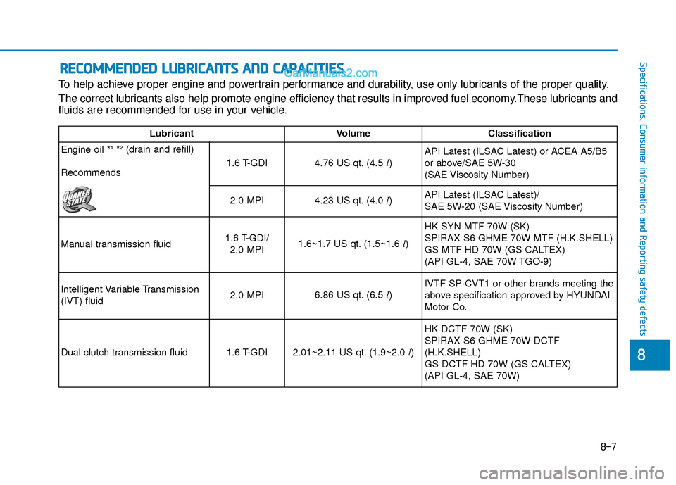
To help achieve proper engine and powertrain performance and durability, use only lubricants of the proper quality.
The correct lubricants also help promote engine efficiency that results in improved fuel economy.These lubricants and
fluids are recommended for use in your vehicle.
R RE
EC
CO
O M
M M
ME
EN
N D
DE
ED
D
L
L U
U B
BR
RI
IC
C A
A N
N T
TS
S
A
A N
N D
D
C
C A
A P
PA
A C
CI
IT
T I
IE
E S
S
LubricantVolume Classification
Engine oil *
1*2(drain and refill)
Recommends
1.6 T-GDI4.76 US qt. (4.5 l)API Latest (ILSAC Latest) or ACEA A5/B5
or above/SAE 5W-30
(SAE Viscosity Number)
2.0 MPI4.23 US qt. (4.0
l)API Latest (ILSAC Latest)/
SAE 5W-20 (SAE Viscosity Number)
Manual transmission fluid
1.6 T-GDI/ 2.0 MPI1.6~1.7 US qt. (1.5~1.6 l) HK SYN MTF 70W (SK)
SPIRAX S6 GHME 70W MTF (H.K.SHELL)
GS MTF HD 70W (GS CALTEX)
(API GL-4, SAE 70W TGO-9)
Intelligent Variable Transmission
(IVT) fluid2.0 MPI6.86 US qt. (6.5 l)
IVTF SP-CVT1 or other brands meeting the
above specification approved by HYUNDAI
Motor Co.
Dual clutch transmission fluid1.6 T-GDI2.01~2.11 US qt. (1.9~2.0 l)
HK DCTF 70W (SK)
SPIRAX S6 GHME 70W DCTF
(H.K.SHELL)
GS DCTF HD 70W (GS CALTEX)
(API GL-4, SAE 70W)
Page 517 of 535
8-8
Specifications, Consumer information and Reporting safety defects
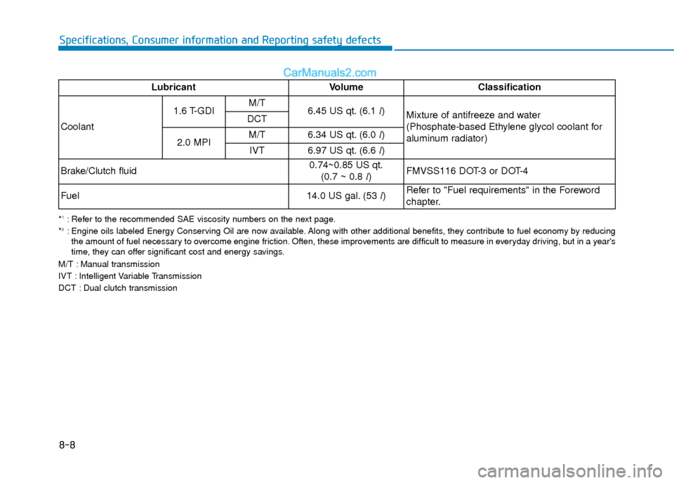
*1: Refer to the recommended SAE viscosity numbers on the next page.
*2: Engine oils labeled Energy Conserving Oil are now available. Along with other additional benefits, they contribute to fuel economy by reducing the amount of fuel necessary to overcome engine friction. Often, these improvements are difficult to measure in everyday driving, but in a year's
time, they can offer significant cost and energy savings.
M/T : Manual transmission
IVT : Intelligent Variable Transmission
DCT : Dual clutch transmission
LubricantVolume Classification
Coolant 1.6 T-GDI
M/T
6.45 US qt. (6.1
l)
Mixture of antifreeze and water
(Phosphate-based Ethylene glycol coolant for
aluminum radiator)
DCT
2.0 MPI M/T
6.34 US qt. (6.0
l)
IVT
6.97 US qt. (6.6 l)
Brake/Clutch fluid
0.74~0.85 US qt. (0.7 ~ 0.8 l) FMVSS116 DOT-3 or DOT-4
Fuel14.0 US gal. (53 l)Refer to "Fuel requirements" in the Foreword
chapter.