stop start Hyundai Elantra 2020 Service Manual
[x] Cancel search | Manufacturer: HYUNDAI, Model Year: 2020, Model line: Elantra, Model: Hyundai Elantra 2020Pages: 535, PDF Size: 16.8 MB
Page 337 of 535
5-101
Driving your vehicle
5
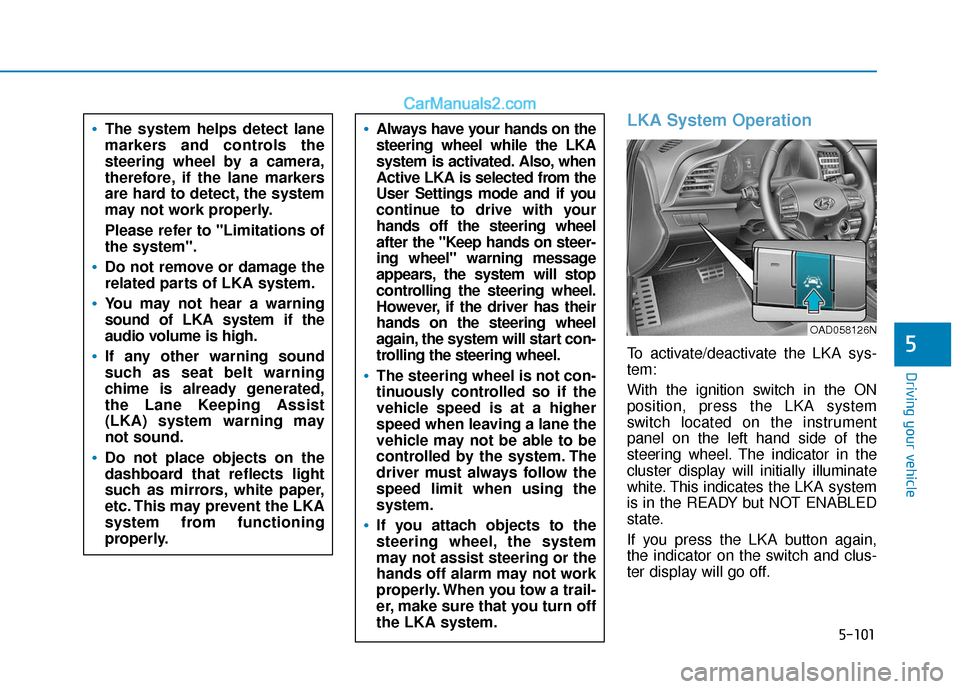
LKA System Operation
To activate/deactivate the LKA sys-
tem:
With the ignition switch in the ON
position, press the LKA system
switch located on the instrument
panel on the left hand side of the
steering wheel. The indicator in the
cluster display will initially illuminate
white. This indicates the LKA system
is in the READY but NOT ENABLED
state.
If you press the LKA button again,
the indicator on the switch and clus-
ter display will go off.
Always have your hands on the
steering wheel while the LKA
system is activated. Also, when
Active LKA is selected from the
User Settings mode and if you
continue to drive with your
hands off the steering wheel
after the "Keep hands on steer-
ing wheel" warning message
appears, the system will stop
controlling the steering wheel.
However, if the driver has their
hands on the steering wheel
again, the system will start con-
trolling the steering wheel.
The steering wheel is not con-
tinuously controlled so if the
vehicle speed is at a higher
speed when leaving a lane the
vehicle may not be able to be
controlled by the system. The
driver must always follow the
speed limit when using the
system.
If you attach objects to the
steering wheel, the system
may not assist steering or the
hands off alarm may not work
properly. When you tow a trail-
er, make sure that you turn off
the LKA system.
The system helps detect lane
markers and controls the
steering wheel by a camera,
therefore, if the lane markers
are hard to detect, the system
may not work properly.
Please refer to "Limitations of
the system".
Do not remove or damage the
related parts of LKA system.
You may not hear a warning
sound of LKA system if the
audio volume is high.
If any other warning sound
such as seat belt warning
chime is already generated,
the Lane Keeping Assist
(LKA) system warning may
not sound.
Do not place objects on the
dashboard that reflects light
such as mirrors, white paper,
etc. This may prevent the LKA
system from functioning
properly.
OAD058126N
Page 346 of 535
5-110
Driving your vehicle
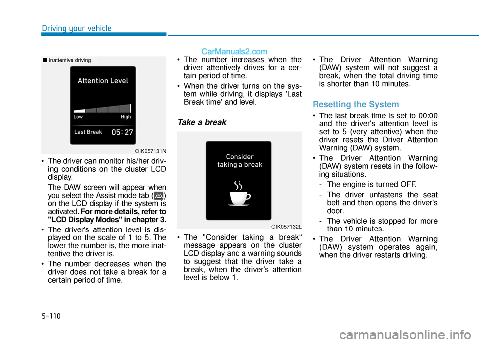
The driver can monitor his/her driv- ing conditions on the cluster LCD
display.
The DAW screen will appear when
you select the Assist mode tab ( )
on the LCD display if the system is
activated. For more details, refer to
"LCD Display Modes" in chapter 3.
The driver's attention level is dis- played on the scale of 1 to 5. The
lower the number is, the more inat-
tentive the driver is.
The number decreases when the driver does not take a break for a
certain period of time. The number increases when the
driver attentively drives for a cer-
tain period of time.
When the driver turns on the sys- tem while driving, it displays 'Last
Break time' and level.
Take a break
The "Consider taking a break“message appears on the cluster
LCD display and a warning sounds
to suggest that the driver take a
break, when the driver’s attention
level is below 1. The Driver Attention Warning
(DAW) system will not suggest a
break, when the total driving time
is shorter than 10 minutes.
Resetting the System
The last break time is set to 00:00and the driver's attention level is
set to 5 (very attentive) when the
driver resets the Driver Attention
Warning (DAW) system.
The Driver Attention Warning (DAW) system resets in the follow-
ing situations.
- The engine is turned OFF.
- The driver unfastens the seat belt and then opens the driver's
door.
- The vehicle is stopped for more than 10 minutes.
The Driver Attention Warning (DAW) system operates again,
when the driver restarts driving.
OIK057132L
OIK057131N
■ Inattentive driving
Page 359 of 535
5-123
Driving your vehicle
5
The driver starts driving by pushingthe toggle switch up (RES+)/down
(SET-) or depressing the accelera-
tor pedal, after stopping the vehicle
with a vehicle stopped far away in
front.
The Forward Collision-Avoidance Assist (FCA) is activated.
The engine is stopped by ISG (Idle Stop and Go) system (if equipped).
Each of these actions will cancel the
Smart Cruise Control operation. The
Set Speed and Vehicle-to-Vehicle
Distance on the cluster LCD display
will go off.
In a condition the Smart Cruise
Control is cancelled automatically,
the Smart Cruise Control will not
resume even though the RES+ or
SET- toggle switch is pushed.
Also, if the Smart Cruise Control is
canceled automatically while the
vehicle is at a standstill, EPB
(Electronic Parking Brake) will be
applied.Information
If the Smart Cruise Control is can-
celed during a situation that is not
described, have the system checked by
an authorized HYUNDAI dealer.
Smart Cruise Control canceled
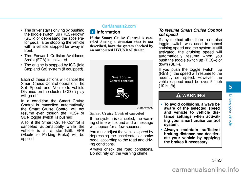
If the system is canceled, the warn-
ing chime will sound and a message
will appear for a few seconds.
You must adjust the vehicle speed by
depressing the accelerator or brake
pedal according to the road and driv-
ing conditions.
Always check the road conditions.
Do not rely on the warning chime.
To resume Smart Cruise Control set speed
If any method other than the cruise
toggle switch was used to cancel
cruising speed and the system is still
activated, the cruising speed will
automatically resume when you
push the toggle switch up (RES+) or
down (SET-).
If you push the toggle switch up
(RES+), the speed will resume to the
recently set speed. However, the
vehicle speed must be over 5 mph
(10 km/h).
i
OIK057096NTo avoid collisions, always be
aware of the selected speed
and vehicle to vehicle dis-
tance settings when activat-
ing your smart cruise control
system.
Always maintain sufficient
braking distance and deceler-
ate your vehicle by applying
the brakes if necessary.
WARNING
Page 385 of 535
6-3
What to do in an emergency
If the Engine Stalls While
Driving
Reduce your speed gradually,keeping a straight line. Move cau-
tiously off the road to a safe place.
Turn on your hazard warning flash- er.
Try to start the engine again. If your vehicle will not start, contact an
authorized HYUNDAI dealer or
seek other qualified assistance.
If the Engine Stalls at a
Crossroad or Crossing
If the engine stalls at a crossroad or
crossing, if safe to do so, move the
shift lever to the N (Neutral) position
and then push the vehicle to a safe
location.
If You Have a Flat Tire While
Driving
If a tire goes flat while you are driv-
ing:
Take your foot off the acceleratorpedal and let the vehicle slow
down while driving straight ahead.
Do not apply the brakes immedi-
ately or attempt to pull off the road
as this may cause loss of vehicle
control resulting in an accident.
When the vehicle has slowed to
such a speed that it is safe to do
so, brake carefully and pull off the
road. Drive off the road as far as
possible and park on firm, level
ground. If you are on a divided
highway, do not park in the median
area between the two traffic lanes.
When the vehicle is stopped, press the hazard warning flasher button,
move the shift lever into P(Park),
and apply the parking brake, and
place the ignition switch in the
LOCK/OFF position.
Have all passengers get out of the vehicle. Be sure they all get out on
the side of the vehicle that is away
from traffic. When changing a flat tire, follow
the instructions provided later in
this chapter.
I IN
N
C
C A
A S
SE
E
O
O F
F
A
A N
N
E
E M
M E
ER
R G
G E
EN
N C
CY
Y
W
W H
HI
IL
L E
E
D
D R
RI
IV
V I
IN
N G
G
6
Page 392 of 535
6-10
What to do in an emergency
Tire Pressure Monitoring
System
Each tire, including the spare (if pro-
vided), should be checked monthly
when cold and inflated to the inflation
pressure recommended by the vehi-
cle manufacturer on the vehicle plac-
ard or tire inflation pressure label.
If your vehicle has tires of a different
size than the size indicated on the
vehicle placard or tire inflation pres-
sure label, you should determine the
proper tire inflation pressure for
those tires.As an added safety feature, your
vehicle has been equipped with a tire
pressure monitoring system (TPMS)
that illuminates a low tire pressure
telltale when one or more of your
tires is significantly under-inflated.
Accordingly, when the low tire pres-
sure telltale illuminates, you should
stop and check your tires as soon as
possible, and inflate them to the
proper pressure. Driving on a signifi-
cantly under-inflated tire causes the
tire to overheat and can lead to tire
failure.
Under-inflation also reduces fuel effi-
ciency and tire tread life, and may
affect the vehicle's handling and
stopping ability.
Please note that the TPMS is not a
substitute for proper tire mainte-
nance, and it is the driver's responsi-
bility to maintain correct tire pres-
sure, even if under-inflation has not
reached the level to trigger illumina-
tion of the TPMS low tire pressure
telltale.Your vehicle has also been equipped
with a TPMS malfunction indicator to
indicate when the system is not
operating properly. The TPMS mal-
function indicator is combined with
the low tire pressure telltale. When
the system detects a malfunction,
the telltale will flash for approximate-
ly one minute and then remain con-
tinuously illuminated. This sequence
will continue upon subsequent vehi-
cle start-ups as long as the malfunc-
tion exists.
When the malfunction indicator is
illuminated, the system may not be
able to detect or signal low tire pres-
sure as intended. TPMS malfunc-
tions may occur for a variety of rea-
sons, including the installation of
replacement or alternate tires or
wheels on the vehicle that prevent
the TPMS from functioning properly.
Always check the TPMS malfunction
telltale after replacing one or more
tires or wheels on your vehicle to
ensure that the replacement or alter-
nate tires and wheels allow the TPMS
to continue to function properly.
Over-inflation or under-inflation
can reduce tire life, adversely
affect vehicle handling, and
lead to sudden tire failure that
may cause loss of vehicle con-
trol resulting in an accident.
WARNING
Page 442 of 535
7-20
Maintenance
Dual Clutch Transmission
Fluid (if equipped)
Inspect the dual clutch transmission
fluid according to the maintenance
schedule.
Manual Transmission Fluid
(if equipped)
Inspect the manual transmission
fluid according to the maintenance
schedule.
Brake Hoses and Lines
Visually check for proper installation,
chafing, cracks, deterioration and
any leakage. Replace any deteriorat-
ed or damaged parts immediately.
Brake/Clutch Fluid
Check brake/clutch fluid level in the
brake/clutch fluid reservoir. The level
should be between the MIN and the
MAX marks on the side of the reser-
voir. Use only hydraulic brake/clutch
fluid conforming to DOT 3 or DOT 4
specification.
Parking Brake
Inspect the parking brake system
including the parking brake pedal
and cables.
Brake Discs, Pads, Calipers
and Rotors
Check the pads for excessive wear,
discs for run out and wear, and
calipers for fluid leakage.
Exhaust Pipe and Muffler
Visually inspect the exhaust pipes,
muffler and hangers for cracks, dete-
rioration, or damage. Start the
engine and listen carefully for any
exhaust gas leakage. Tighten con-
nections or replace parts as neces-
sary.
Suspension Mounting Bolts
Check the suspension connections
for looseness or damage. Retighten
to the specified torque.
Steering Gear Box, Linkage &
Boots/Lower Arm Ball Joint
With the vehicle stopped and the
engine off, check for excessive free-
play in the steering wheel. Check the
linkage for bends or damage. Check
the dust boots and ball joints for
deterioration, cracks, or damage.
Replace any damaged parts.
Drive Shafts and Boots
Check the drive shafts, boots and
clamps for cracks, deterioration, or
damage. Replace any damaged
parts and, if necessary, repack the
grease.
Air Conditioning Refrigerant
Check the air conditioning lines and
connections for leakage and dam-
age.
Page 447 of 535
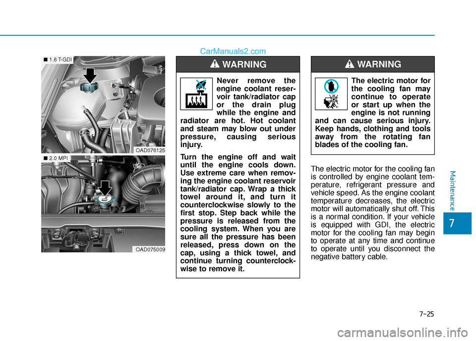
The electric motor for the cooling fan
is controlled by engine coolant tem-
perature, refrigerant pressure and
vehicle speed. As the engine coolant
temperature decreases, the electric
motor will automatically shut off. This
is a normal condition. If your vehicle
is equipped with GDI, the electric
motor for the cooling fan may begin
to operate at any time and continue
to operate until you disconnect the
negative battery cable.
7-25
7
Maintenance
The electric motor for
the cooling fan may
continue to operate
or start up when the
engine is not running
and can cause serious injury.
Keep hands, clothing and tools
away from the rotating fan
blades of the cooling fan.
WARNING
OAD076125
■ 1.6 T-GDI
OAD075009
■2.0 MPI
Never remove the
engine coolant reser-
voir tank/radiator cap
or the drain plug
while the engine and
radiator are hot. Hot coolant
and steam may blow out under
pressure, causing serious
injury.
Turn the engine off and wait
until the engine cools down.
Use extreme care when remov-
ing the engine coolant reservoir
tank/radiator cap. Wrap a thick
towel around it, and turn it
counterclockwise slowly to the
first stop. Step back while the
pressure is released from the
cooling system. When you are
sure all the pressure has been
released, press down on the
cap, using a thick towel, and
continue turning counterclock-
wise to remove it.
WARNING
Page 457 of 535
7-35
7
Maintenance
B
BA
A T
TT
TE
ER
R Y
Y
To prevent SERIOUS INJURY or
DEATH to you or bystanders,
always follow these precautions
when working near or handling
the battery:
Always read and follow
instructions carefully
when handling a battery.Wear eye protection
designed to protect the
eyes from acid splashes.
Keep all flames, sparks,
or smoking materials
away from the battery.
Hydrogen is always present in battery cells,
is highly combustible,
and may explode if ignit-
ed.
Keep batteries out of
reach of children.
WARNING Batteries contain sulfu-
ric acid which is highly
corrosive. Do not allow
acid to contact your
eyes, skin or clothing.
If acid gets into your eyes, flush
your eyes with clean water for at
least 15 minutes and get imme-
diate medical attention. If acid
gets on your skin, thoroughly
wash the area. If you feel pain or
a burning sensation, get med-
ical attention immediately.
When lifting a plastic-cased
battery, excessive pressure
on the case may cause battery
acid to leak. Lift with a battery
carrier or with your hands on
opposite corners.
Do not attempt to jump start
your vehicle if your battery is
frozen.
NEVER attempt to recharge
the battery when the vehicle’s
battery cables are connected
to the battery.
The electrical ignition system
works with high voltage.
NEVER touch these compo-
nents with the engine running
or when the Engine Start/Stop
button is in the ON position.
Leaked battery electrolyte due
to repeated driving on sharp
curves (e.g. on circuits) may
cause safety problem. Avoid
repeated driving on sharp
curves.
CALIFORNIA PROPOSITION 65
WARNING
Battery posts, terminals, and
related accessories contain
lead and lead compounds,
chemicals known to the State of
California to cause cancer, birth
defects and reproductive harm.
Batteries also contain other
chemicals known to the State of
California to cause cancer.
Wash hands after handling.
WARNING
Page 459 of 535
7-37
7
Maintenance
By jump starting
After a jump start from a good bat-
tery, drive the vehicle for 20-30 min-
utes before it is shutoff. The vehicle
may not restart if you shut it off
before the battery had a chance to
adequately recharge. See "Jump
Starting" in chapter 6 for more infor-
mation on jump starting procedures.
Information
An inappropriately disposedbattery can be harmful to
the environment and human
health.
Dispose the battery according to your
local law(s) or regulation.
Reset Features
The following items may need to be
reset after the battery has been dis-
charged or the battery has been dis-
connected.
Power Windows
Trip Computer
Climate Control System
Clock
Audio System
Sunroof
i
Watch the battery during
charging, and stop or reduce
the charging rate if the battery
cells begin boiling violently.
The negative battery cable
must be removed first and
installed last when the battery
is disconnected. Disconnect
the battery charger in the fol-
lowing order:
(1) Turn off the battery charg- er main switch.
(2) Unhook the negative
clamp from the negative
battery terminal.
(3) Unhook the positive clamp from the positive battery
terminal.
Always use a genuine
HYUNDAI approved battery
when you replace the battery.
Page 482 of 535
7-60
Maintenance
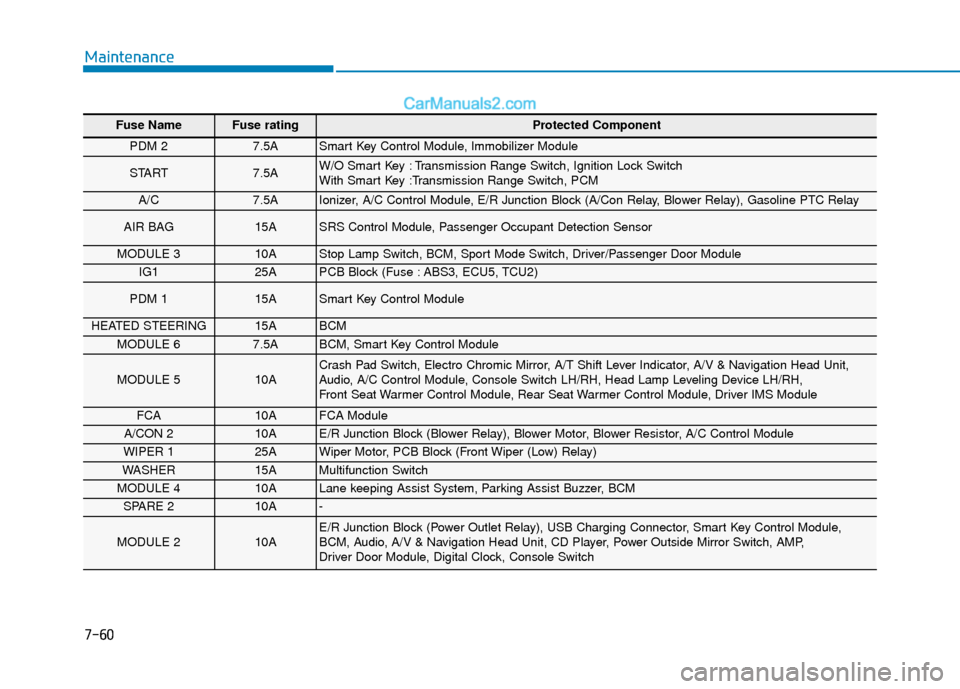
Fuse Name Fuse rating Protected Component
PDM 2 7.5A Smart Key Control Module, Immobilizer Module
START 7.5A W/O Smart Key : Transmission Range Switch, Ignition Lock Switch
With Smart Key :Transmission Range Switch, PCM
A/C7.5A Ionizer, A/C Control Module, E/R Junction Block (A/Con Relay, Blower Relay), Gasoline PTC Relay
AIR BAG 15A SRS Control Module, Passenger Occupant Detection Sensor
MODULE 3 10A Stop Lamp Switch, BCM, Sport Mode Switch, Driver/Passenger Door Module
IG1 25A PCB Block (Fuse : ABS3, ECU5, TCU2)
PDM 1 15A Smart Key Control Module
HEATED STEERING 15A BCM
MODULE 6 7.5A BCM, Smart Key Control Module
MODULE 5 10A Crash Pad Switch, Electro Chromic Mirror, A/T Shift Lever Indicator, A/V & Navigation Head Unit,
Audio, A/C Control Module, Console Switch LH/RH, Head Lamp Leveling Device LH/RH,
Front Seat Warmer Control Module, Rear Seat Warmer Control Module, Driver IMS Module
FCA10A FCA Module
A/CON 2 10A E/R Junction Block (Blower Relay), Blower Motor, Blower Resistor, A/C Control Module
WIPER 1 25A Wiper Motor, PCB Block (Front Wiper (Low) Relay)
WASHER 15A Multifunction Switch
MODULE 4 10A Lane keeping Assist System, Parking Assist Buzzer, BCM
SPARE 2 10A -
MODULE 2 10A E/R Junction Block (Power Outlet Relay), USB Charging Connector, Smart Key Control Module,
BCM, Audio, A/V & Navigation Head Unit, CD Player, Power Outside Mirror Switch, AMP,
Driver Door Module, Digital Clock, Console Switch