coolant temperature HYUNDAI ELANTRA 2021 Owners Manual
[x] Cancel search | Manufacturer: HYUNDAI, Model Year: 2021, Model line: ELANTRA, Model: HYUNDAI ELANTRA 2021Pages: 570, PDF Size: 52.21 MB
Page 87 of 570
Instrument Cluster
4
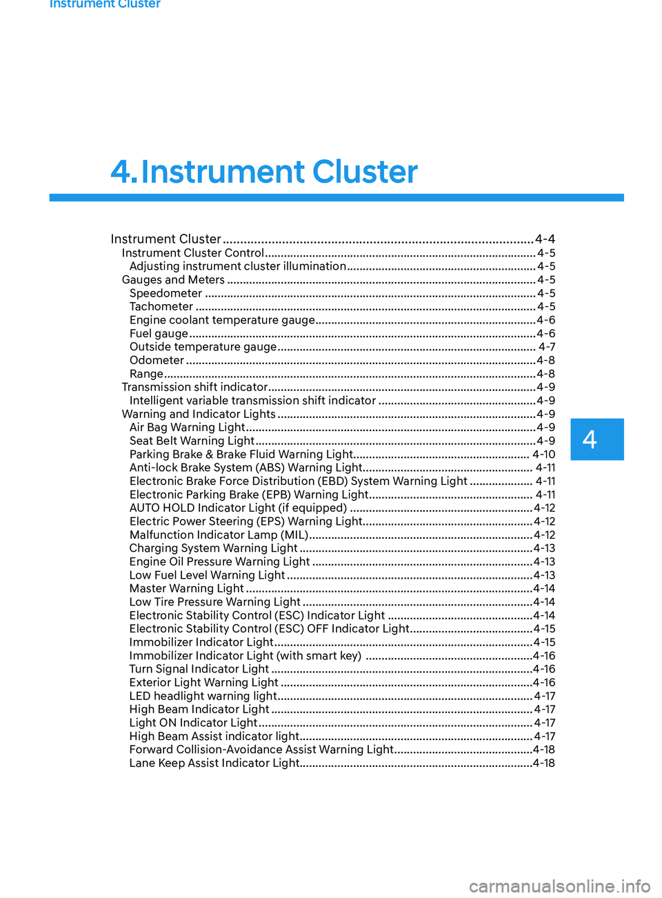
Instrument Cluster ........................................................................\
.................4-4Instrument Cluster Control ........................................................................\
..............4-5
Adjus ting instrument cluster illumination ............................................................ 4-5
Gauges and Me
ters
........................................................................\
.......................... 4-5
Speedome
ter
........................................................................\
................................. 4-5
T
achometer
........................................................................\
.................................... 4-5
E
ngine coolant temperature gauge
...................................................................... 4-6
Fuel gauge ........................................................................\
.....................................
.4-6
Outside temperature gauge
........................................................................\
.......... 4
-7
Odometer
........................................................................\
.....................................
..4-8
Range
........................................................................\
.............................................. 4-8
T
ransmission shift indicator
........................................................................\
............. 4-9
In
telligent variable transmission shift indicator
.................................................. 4-9
W
arning and Indicator Lights
........................................................................\
.......... 4-9
Air Bag W
arning Light
........................................................................\
.................... 4-9
Sea
t Belt Warning Light
........................................................................\
................. 4-9
P
arking Brake & Brake Fluid Warning Light
........................................................ 4-
10
Anti-lock Brake System (ABS) Warning Light
...................................................... 4-
11
Electronic Brake Force Distribution (EBD) System Warning Light
.................... 4-
11
Electronic Parking Brake (EPB) Warning Light
.................................................... 4-
11
AUTO HOLD Indicator Light (if equipped)
.......................................................... 4-
12
Electric Power Steering (EPS) Warning Light
...................................................... 4-
12
Malfunction Indicator Lamp (MIL)
....................................................................... 4-12
Char
ging System Warning Light
........................................................................\
.. 4-
13
Engine Oil Pressure Warning Light
...................................................................... 4-13
L
ow Fuel Level Warning Light
........................................................................\
...... 4-
13
Master Warning Light
........................................................................\
................... 4-
14
Low Tire Pressure Warning Light
........................................................................\
. 4-
14
Electronic Stability Control (ESC) Indicator Light
.............................................. 4-
14
Electronic Stability Control (ESC) OFF Indicator Light
....................................... 4-
15
Immobilizer Indicator Light
........................................................................\
.......... 4-
15
Immobilizer Indicator Light (with smart key)
..................................................... 4-16
T
urn Signal Indicator Light
........................................................................\
........... 4-
16
Exterior Light Warning Light
........................................................................\
........ 4-
16
LED headlight warning light
........................................................................\
......... 4-
17
High Beam Indicator Light
........................................................................\
........... 4-
17
Light ON Indicator Light
........................................................................\
............... 4-
17
High Beam Assist indicator light
........................................................................\
.. 4-
17
Forward Collision-Avoidance Assist Warning Light
............................................ 4-
18
Lane Keep Assist Indicator Light........................................................................\
..4-18
4. Instrument Cluster
Page 92 of 570
Instrument Cluster
4-6
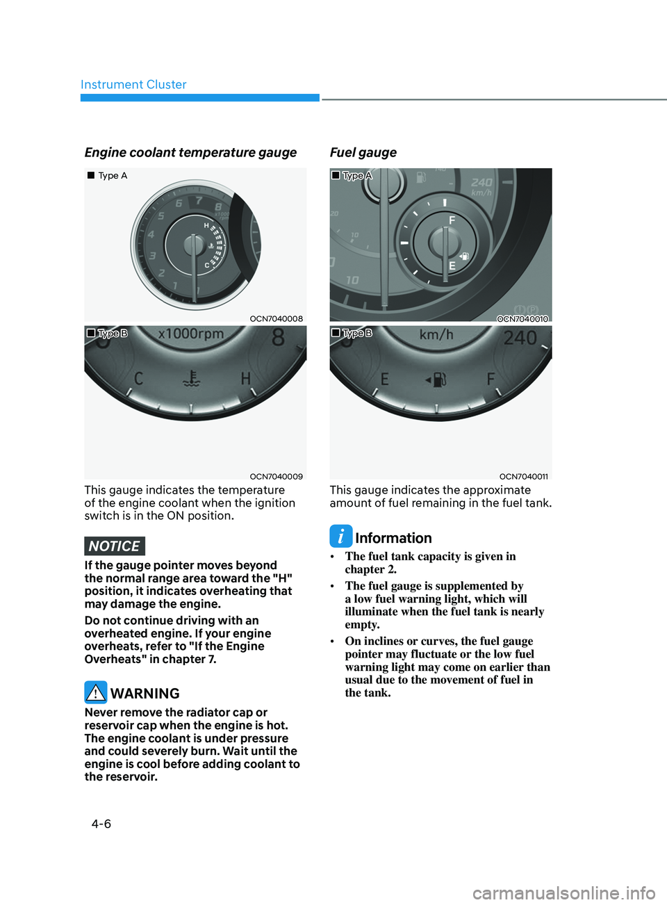
Engine coolant temperature gauge
OCN7040008
OCN7040009
„„Type A
„
„Type B
This gauge indicates the temperature
of the engine coolant when the ignition
switch is in the ON position.
NOTICE
If the gauge pointer moves beyond
the normal range area toward the "H"
position, it indicates overheating that
may damage the engine.
Do not continue driving with an
overheated engine. If your engine
overheats, refer to "If the Engine
Overheats" in chapter 7.
WARNING
Never remove the radiator cap or
reservoir cap when the engine is hot.
The engine coolant is under pressure
and could severely burn. Wait until the
engine is cool before adding coolant to
the reservoir.
Fuel gauge
OCN7040010
OCN7040011
„„Type B
„
„Type A
This gauge indicates the approximate
amount of fuel remaining in the fuel tank.
Information
•
The fuel tank capacity is given in
chapter 2.
• The fuel gauge is supplemented by
a low fuel warning light, which will
illuminate when the fuel tank is nearly
empty.
• On inclines or curves, the fuel gauge
pointer may fluctuate or the low fuel
warning light may come on earlier than
usual due to the movement of fuel in
the tank.
Page 108 of 570
Instrument Cluster
4-22
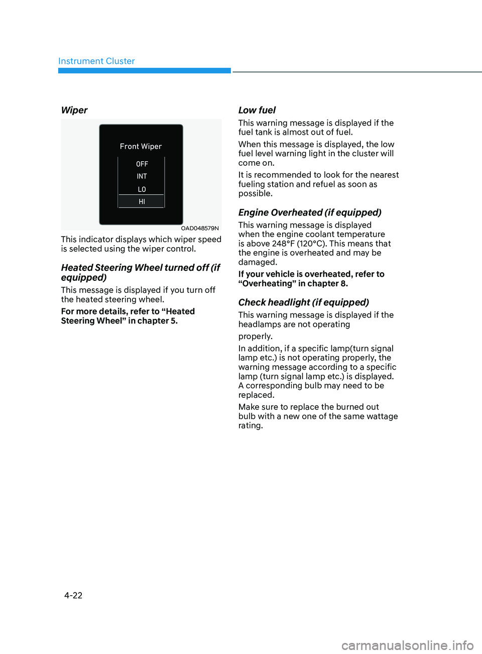
Wiper
OAD048579N
This indicator displays which wiper speed
is selected using the wiper control.
Heated Steering Wheel turned off (if
equipped)
This message is displayed if you turn off
the heated steering wheel.
For more details, refer to “Heated
Steering Wheel” in chapter 5.
Low fuel
This warning message is displayed if the
fuel tank is almost out of fuel.
When this message is displayed, the low
fuel level warning light in the cluster will
come on.
It is recommended to look for the nearest
fueling station and refuel as soon as
possible.
Engine Overheated (if equipped)
This warning message is displayed
when the engine coolant temperature
is above 248°F (120°C). This means that
the engine is overheated and may be
damaged.
If your vehicle is overheated, refer to
“Overheating” in chapter 8.
Check headlight (if equipped)
This warning message is displayed if the
headlamps are not operating
properly.
In addition, if a specific lamp(turn signal
lamp etc.) is not operating properly, the
warning message according to a specific
lamp (turn signal lamp etc.) is displayed.
A corresponding bulb may need to be
replaced.
Make sure to replace the burned out
bulb with a new one of the same wattage
rating.
Page 306 of 570
06
6-47
WARNING
The use of tire chains may adversely
affect vehicle handling:
• Drive less than 20 mph (30 km/h)
or the chain manufacturer's
recommended speed limit,
whichever is lower.
• Drive carefully and avoid bumps,
holes, sharp turns, and other road
hazards, which may cause the
vehicle to bounce.
• Avoid sharp turns or locked wheel
braking.
Information
• Install tire chains on both left and right
front tires. It should be noted that
installing tire chains on the tires will
provide a greater driving force, but will
not prevent side skids.
• Do not install studded tires without
first checking local, state and municipal
regulations for possible restrictions
against their use.
Chain installation
When installing tire chains, follow the
manufacturer’s instructions and mount
them as tightly possible. Drive slowly
(less than 20 mph (30 km/h)) with
chains installed. If you hear the chains
contacting the body or chassis, stop and
tighten them. If they still make contact,
slow down until the noise stops. Remove
the tire chains as soon as you begin
driving on cleared roads.
When mounting snow chains, park the
vehicle on level ground away from traffic.
Turn on the vehicle Hazard Warning
Flasher and place a triangular emergency
warning device behind the vehicle (if
available). Always place the vehicle in P
(Park), apply the parking brake and turn
off the engine before installing snow
chains.
NOTICE
When using tire chains:
• Wrong size chains or improperly
installed chains can damage your
vehicle's brake lines, suspension,
body and wheels.
• Use SAE "S" class or wire chains.
• If you hear noise caused by chains
contacting the body, retighten the
chain to prevent contact with the
vehicle body.
• To prevent body damage, retighten
the chains after driving 0.3~0.6 miles
(0.5~1.0 km).
• Do not use tire chains on vehicles
equipped with aluminum wheels. If
unavoidable, use a wire type chain.
• Use wire chains less than 0.59 inch
(15mm) wide to prevent damage to
the chain’s connection.
Winter Precautions
Use high quality ethylene glycol
coolant
Your vehicle is delivered with high
quality ethylene glycol coolant in the
cooling system. It is the only type of
coolant that should be used because it
helps prevent corrosion in the cooling
system, lubricates the water pump and
prevents freezing. Be sure to replace or
replenish your coolant in accordance
with the maintenance schedule in
chapter 8. Before winter, have your
coolant tested to assure that its freezing
point is sufficient for the temperatures
anticipated during the winter.
Page 469 of 570
Emergency Situations
8-6
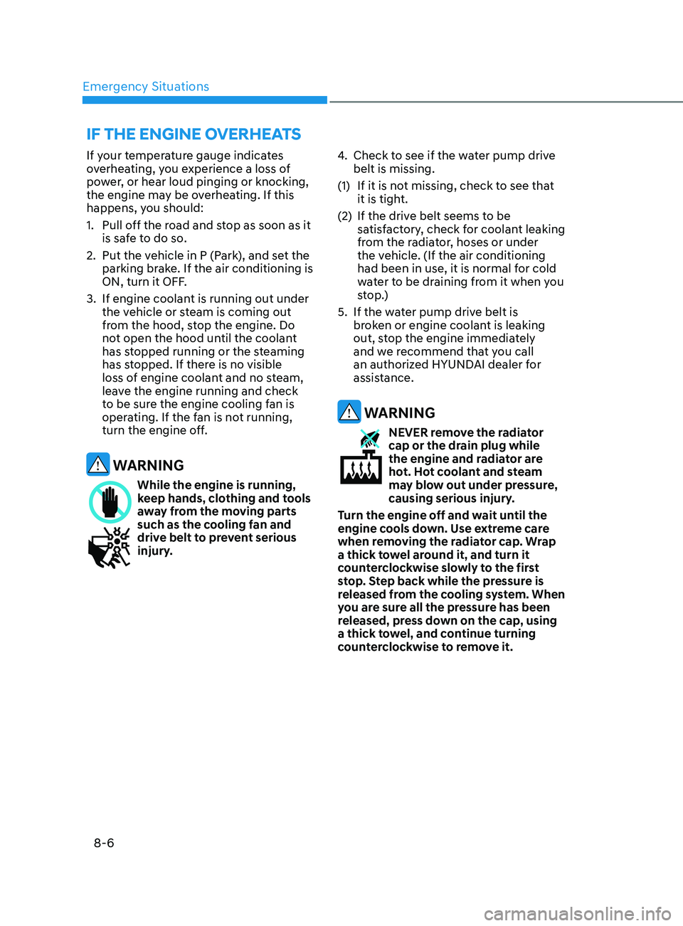
If your temperature gauge indicates
overheating, you experience a loss of
power, or hear loud pinging or knocking,
the engine may be overheating. If this
happens, you should:
1.
Pull off the r
oad and stop as soon as it
is safe to do so.
2.
Put the vehicle in P (P
ark), and set the
parking brake. If the air conditioning is
ON, turn it OFF.
3.
If engine coolant is running out under
the v
ehicle or steam is coming out
from the hood, stop the engine. Do
not open the hood until the coolant
has stopped running or the steaming
has stopped. If there is no visible
loss of engine coolant and no steam,
leave the engine running and check
to be sure the engine cooling fan is
operating. If the fan is not running,
turn the engine off.
WARNING
While the engine is running,
keep hands, clothing and tools
away from the moving parts
such as the cooling fan and
drive belt to prevent serious
injury. 4.
Check to see if the w
ater pump drive
belt is missing.
(1)
If it is not missing, check t
o see that
it is tight.
(2)
If the drive belt seems t
o be
satisfactory, check for coolant leaking
from the radiator, hoses or under
the vehicle. (If the air conditioning
had been in use, it is normal for cold
water to be draining from it when you
stop.)
5.
If the wa
ter pump drive belt is
broken or engine coolant is leaking
out, stop the engine immediately
and we recommend that you call
an authorized HYUNDAI dealer for
assistance.
WARNING
NEVER remove the radiator
cap or the drain plug while
the engine and radiator are
hot. Hot coolant and steam
may blow out under pressure,
causing serious injury.
Turn the engine off and wait until the
engine cools down. Use extreme care
when removing the radiator cap. Wrap
a thick towel around it, and turn it
counterclockwise slowly to the first
stop. Step back while the pressure is
released from the cooling system. When
you are sure all the pressure has been
released, press down on the cap, using
a thick towel, and continue turning
counterclockwise to remove it.
If the engIne overheats
Page 470 of 570
08
8 -7
6. If you cannot find the cause of the
overheating, wait until the engine
temperature has returned to normal.
Then, if coolant has been lost,
carefully add coolant to the reservoir
to bring the fluid level in the reservoir
up to the halfway mark.
7.
Proceed with caution, k
eeping alert
for further signs of overheating.
If overheating happens again,
we recommend that you call an
authorized HYUNDAI dealer for
assistance.NOTICE
• Serious loss of coolant indicates a
leak in the cooling system and we
recommend the system be checked
by an authorized HYUNDAI dealer.
• When the engine overheats from
low engine coolant, suddenly adding
engine coolant may cause cracks
in the engine. To prevent damage,
add engine coolant slowly in small
quantities.
Page 503 of 570
09
9-17
Recommended engine coolant
• When adding coolant, use only
distilled (deionized) water for your
vehicle and never mix hard water in
the coolant filled at the factory.
• An improper coolant mixture can
result in severe malfunction or engine
damage.
• The engine in your vehicle has
aluminum engine parts and must be
protected by an ethylene-glycol with
phosphate based coolant to prevent
corrosion and freezing.
• Do not use alcohol or methanol
coolant or mix them with the specified
coolant.
• Do not use a solution that contains
more than 60% antifreeze or less than
35% antifreeze, which would reduce
the effectiveness of the solution.
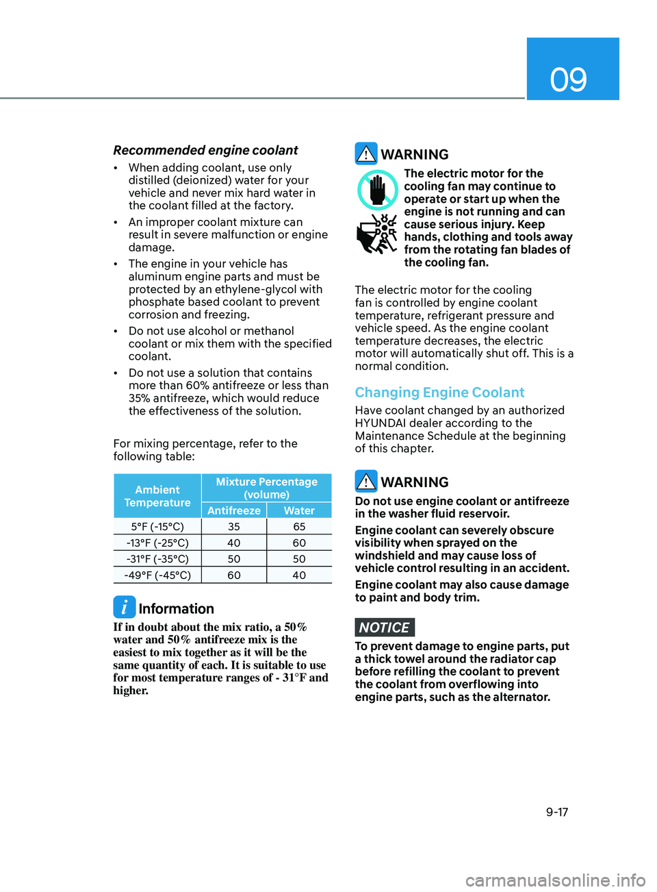
For mixing percentage, refer to the
following table:
Ambient
Temperature Mixture Percentage
(volume)
Antifreeze Water
5°F (-15°C) 35 65
-13°F (-25°C) 40 60
-31°F (-35°C) 50 50
-49°F (-45°C) 60 40
Information
If in doubt about the mix ratio, a 50%
water and 50% antifreeze mix is the
easiest to mix together as it will be the
same quantity of each. It is suitable to use
for most temperature ranges of - 31°F and
higher.
WARNING
The electric motor for the
cooling fan may continue to
operate or start up when the
engine is not running and can
cause serious injury. Keep
hands, clothing and tools away
from the rotating fan blades of
the cooling fan.
The electric motor for the cooling
fan is controlled by engine coolant
temperature, refrigerant pressure and
vehicle speed. As the engine coolant
temperature decreases, the electric
motor will automatically shut off. This is a
normal condition.
Changing Engine Coolant
Have coolant changed by an authorized
HYUNDAI dealer according to the
Maintenance Schedule at the beginning
of this chapter.
WARNING
Do not use engine coolant or antifreeze
in the washer fluid reservoir.
Engine coolant can severely obscure
visibility when sprayed on the
windshield and may cause loss of
vehicle control resulting in an accident.
Engine coolant may also cause damage
to paint and body trim.
NOTICE
To prevent damage to engine parts, put
a thick towel around the radiator cap
before refilling the coolant to prevent
the coolant from overflowing into
engine parts, such as the alternator.
Page 554 of 570
Maintenance
9-68
The emission control system of your
vehicle is covered by a written limited
warranty. Please see the warranty
information contained in the Owner’s
Handbook & Warranty Information
booklet in your vehicle.
Your vehicle is equipped with an
emission control system to meet all
applicable emission regulations. There
are three emission control systems, as
follows.
(1)
Crank
case emission control system
(2)
Ev
aporative emission control system
(3)
Exhaust emission con
trol system
In order to ensure the proper function
of the emission control systems, it
is recommended that you have your
vehicle inspected and maintained
by an authorized HYUNDAI dealer in
accordance with the maintenance
schedule in this manual.
NOTICE
For the Inspection and Maintenance
Test (with Electronic Stability Control
(ESC) system)
• To prevent the vehicle from misfiring
during dynamometer testing, turn
the Electronic Stability Control
(ESC) system off by pressing the ESC
switch (ESC OFF light illuminated).
• After dynamometer testing is
completed, turn the ESC system back
on by pressing the ESC switch again.
1. Crankcase Emission Control
Sy
stem
The positive crankcase ventilation system
is employed to prevent air pollution
caused by blow-by gases being emitted
from the crankcase. This system supplies
fresh filtered air to the crankcase through
the air intake hose. Inside the crankcase,
the fresh air mixes with blow-by gases,
which then pass through the PCV valve
into the induction system.
2. Evaporative Emission Control
System Including Onboard
Refueling Vapor Recovery
(ORVR)
The Evaporative Emission Control System
is designed to prevent fuel vapors from
escaping into the atmosphere. The
ORVR system is designed to allow the
vapors from the fuel tank to be loaded
into a canister while refueling at the gas
station, preventing the escape of fuel
vapors into the atmosphere.
Canister
Fuel vapors generated inside the fuel
tank are absorbed and stored in the
onboard canister. When the engine is
running, the fuel vapors absorbed in the
canister are drawn into the surge tank
through the purge control solenoid valve.
Purge Control Solenoid Valve (PCSV)
The purge control solenoid valve
is controlled by the Engine Control
Module (ECM); when the engine coolant
temperature is low during idling, the
PCSV closes so that evaporated fuel
is not taken into the engine. After the
engine warms-up during ordinary
driving, the PCSV opens to introduce
evaporated fuel to the engine.
EmiSSion Control SyStEm