turn signal Hyundai Elantra GT 2016 Owner's Manual
[x] Cancel search | Manufacturer: HYUNDAI, Model Year: 2016, Model line: Elantra GT, Model: Hyundai Elantra GT 2016Pages: 546, PDF Size: 14.04 MB
Page 18 of 546
25
Your vehicle at a glance
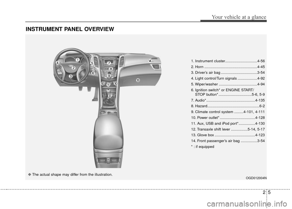
INSTRUMENT PANEL OVERVIEW
OGD012004N❈ The actual shape may differ from the illustration. 1. Instrument cluster...............................4-56
2. Horn ...................................................4-45
3. Driver’s air bag ...................................3-54
4. Light control/Turn signals ...................4-92
5. Wiper/washer .....................................4-94
6. Ignition switch* or ENGINE START/
STOP button* ................................5-6, 5-9
7. Audio* ...............................................4-135
8. Hazard..................................................6-2
9. Climate control system .........4-101, 4-111
10. Power outlet* ..................................4-128
11. Aux, USB and iPod port*................4-130
12. Transaxle shift lever ................5-14, 5-17
13. Glove box .......................................4-123
14. Front passenger’s air bag ................3-54
* : if equipped
Page 60 of 546

341
Safety features of your vehicle
How does the air bag system
operate
Air bags are activated (able toinflate if necessary) only when the
ignition switch is turned to the ON
or START position.
Air bags inflate instantly in the event of serious frontal or side col-
lision in order to help protect the
occupants from serious physical
injury.
There is no single speed at which the air bags will inflate.
Generally, air bags are designed to
inflate by the severity of a collision
and its direction. These two factors
determine whether the sensors
send out an electronic deployment/
inflation signal.
Air bag deployment depends on a number of factors including vehicle
speed, angles of impact and the
density and stiffness of the vehi-
cles or objects which your vehicle
hits in the collision. Though, factors
are not limited to those mentioned
above. The front air bags will completely
inflate and deflate in an instant.
It is virtually impossible for you to
see the air bags inflate during an
accident.
It is much more likely that you will
simply see the deflated air bags
hanging out of their storage com-
partments after the collision.
In order to help provide protection in a severe collision, the air bags
must inflate rapidly. The speed of
air bag inflation is a consequence
of the extremely short time in
which a collision occurs and the
need to get the air bag between
the occupant and the vehicle struc-
tures before the occupant impacts
those structures. This speed of
inflation reduces the risk of serious
or life-threatening injuries in a
severe collision and is thus a nec-
essary part of air bag design. However, air bag inflation can also
cause injuries which normally can
include facial abrasions, bruises
and broken bones because the
inflation speed also causes the air
bags to expand with a great deal of
force.
There are even circumstances under which contact with the air
bag can cause fatal injuries, espe-
cially if the occupant is positioned
excessively close to the air bag.
Page 92 of 546
45
Features of your vehicle
Immobilizer system
(if equipped)
Your vehicle is equipped with an
electronic engine immobilizer system
to reduce the risk of unauthorized
vehicle use.
Your immobilizer system is com-
prised of a small transponder in the
ignition key and electronic devices
inside the vehicle.
With the immobilizer system, when-
ever you insert your ignition key into
the ignition switch and turn it to ON,
it checks and determines and verifies
if the ignition key is valid.
If the key is determined to be valid,
the engine will start.
If the key is determined to be invalid,
the engine will not start.
To activate the immobilizer sys-tem:
Turn the ignition key to the OFF posi-
tion. The immobilizer system acti-
vates automatically. Without a valid
ignition key for your vehicle, the
engine will not start.
To deactivate the immobilizersystem:
Insert the ignition key into the key
cylinder and turn it to the ON position.
✽ ✽ NOTICE
When starting the engine, do not use
the key with other immobilizer keys
around. Otherwise the engine may
not start or may stop soon after it
starts. Keep each key separate in
order to avoid a starting malfunction.
✽ ✽NOTICE
If you need additional keys or lose
your keys, consult an authorized
HYUNDAI dealer.
WARNING
In order to prevent theft of your
vehicle, do not leave spare keys
anywhere in your vehicle. Your
Immobilizer password is a cus-
tomer unique password and
should be kept confidential. Do
not leave this number anywhere
in your vehicle.
CAUTION
Do not put metal accessories
near the ignition switch.
Metal accessories may interruptthe transponder signal and mayprevent the engine from beingstarted.
Page 98 of 546
411
Features of your vehicle
Smart key immobilizer system
Your vehicle is equipped with an
electronic engine immobilizer system
to reduce the risk of unauthorized
vehicle use.
Your immobilizer system is com-
prised of a small transponder in the
smart key and electronic devices
inside the vehicle.
With the immobilizer system, when-
ever you turn the engine start/stop
button to the ON position by pressing
the button while carrying the smart
key, it checks and determines and
verifies if the smart key is valid or
not.
If the key is determined to be valid,
the engine will start.
If the key is determined to be invalid,
the engine will not start.
To deactivate the immobilizersystem:
Turn the engine start/stop button to
the ON position by pressing the but-
ton while carrying the smart key.
To activate the immobilizer system:
Turn the engine start/stop button to
the OFF position. The immobilizer
system activates automatically.
Without a valid smart key for your
vehicle, the engine will not start.
✽ ✽ NOTICE
When starting the engine, do not use
the key with other immobilizer keys
around. Otherwise the engine may
not start or may stop soon after it
starts. Keep each key separate in
order to avoid a starting malfunction.
✽ ✽NOTICE
If you need additional keys or lose
your keys, consult an authorized
HYUNDAI dealer.
CAUTION
In order to prevent theft of your
vehicle, do not leave spare keysanywhere in your vehicle. YourImmobilizer password is a cus-tomer unique password andshould be kept confidential. Donot leave this number anywherein your vehicle.
CAUTION
Do not put metal accessoriesnear the smart key.
The engine may not startbecause the metal accessoriesmay interrupt the transpondersignal from transmitting normal-ly.
Page 136 of 546

449
Features of your vehicle
Electric chromic mirror withhomelink system (if equipped)
To operate the electric rearview mirror
Press the I button (1) to turn the
automatic- dimming function on. The
mirror indicator light will illuminate.
Press the O button (2) to turn the
automatic- dimming function off. The
mirror indicator light will turn off. HomeLink
®Wireless Control System
Your new mirror comes with an inte-
grated HomeLink Universal
Transceiver, which allows you to pro-
gram the mirror to activate your
garage door(s), estate gate, home
lighting, etc. The mirror actually
learns the codes from your various
existing transmitters.
OHD046025NOHD046305N
Glare detection sensor
Indicator light
Homelink buttons
WARNING
When programming theHomeLink®Wireless Control
System, you may be operating
a garage door or gate operator.
Make sure that people and
objects are out of the way of
the moving door or gate to pre-
vent potential harm or damage.
Do not use HomeLink with any garage door opener that
lacks the safety stop and
reverse feature as required by
federal safety standards. (This
includes any garage door
opener model manufactured
before April 1, 1982.) A garage
door opener which cannot
detect an object, signaling the
door to stop and reverse,
does not meet current federal
safety standards. Using a
garage door opener without
these features increases risk
of serious injury or death. For
more information, call 1-800-
355-3515 or on the internet at
www.homelink.com.
Page 139 of 546
Features of your vehicle
52
4
Rolling code programming
To train a garage door opener (or
other rolling code equipped devices)
with the rolling code feature, follow
these instructions after completing
the “Programming” portion of this
text. (A second person may make the
following training procedures quicker
& easier.)
4. Locate the “learn” or “smart” but-
ton on the device’s motor head
unit. Exact location and color of
the button may vary by product
brand. If there is difficulty locating
the “learn” or “smart” button, refer-
ence the device’s owner’s manual
or contact HomeLink at 1-800-
355-3515 or on the internet at
www.homelink.com.
5. Press and release the “learn” or “smart” button on the device’s
motor head unit. You have 30
seconds to complete step num-
ber 6. 6. Return to the vehicle and firmly
press and release the pro-
grammed HomeLink button up to
three times. The rolling code
equipped device should now rec-
ognize the HomeLink signal and
activate when the HomeLink but-
ton is pressed. The remaining two
buttons may now be programmed
if this has not previously been
done. Refer to the “Programming”
portion of this text. Operating HomeLink
To operate, simply press the pro-
grammed HomeLink button.
Activation will now occur for the
trained product (garage door, securi-
ty system, entry door lock, estate
gate, or home or office lighting). For
convenience, the hand-held trans-
mitter of the device may also be used
at any time. The HomeLink Wireless
Controls System (once programmed)
or the original hand-held transmitter
may be used to activate the device
(e.g. garage door, entry door lock,
etc.). In the event that there are still
programming difficulties, contact
HomeLink at 1-800-355-3515 or on
the internet at www.homelink.com.
Page 143 of 546
Features of your vehicle
56
4
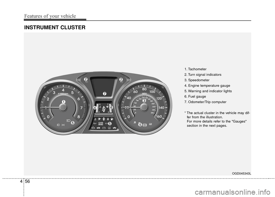
INSTRUMENT CLUSTER
OGD045343L
1. Tachometer
2. Turn signal indicators
3. Speedometer
4. Engine temperature gauge
5. Warning and indicator lights
6. Fuel gauge
7. Odometer/Trip computer
* The actual cluster in the vehicle may dif-
fer from the illustration.
For more details refer to the "Gauges"
section in the next pages.
Page 155 of 546
Features of your vehicle
68
4
ItemsExplanation
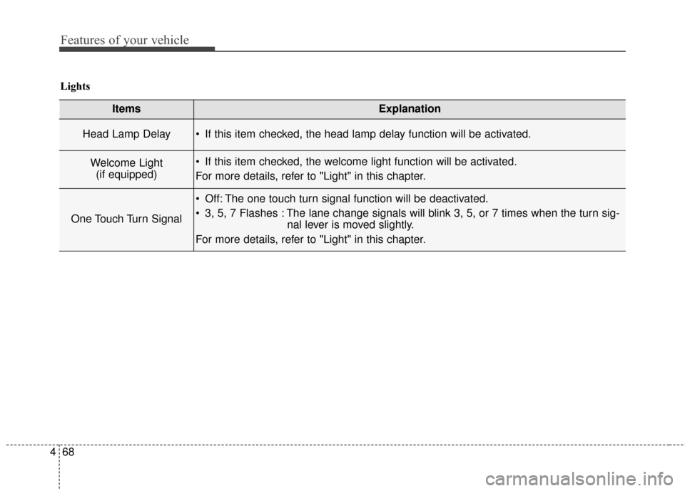
Head Lamp Delay If this item checked, the head lamp delay function will be activated.
Welcome Light
(if equipped) If this item checked, the welcome light function will be activated.
For more details, refer to "Light" in this chapter.
One Touch Turn Signal
Off: The one touch turn signal function will be deactivated.
3, 5, 7 Flashes : The lane change signals will blink 3, 5, or 7 times when the turn sig- nal lever is moved slightly.
For more details, refer to "Light" in this chapter.
Lights
Page 161 of 546
Features of your vehicle
74
4
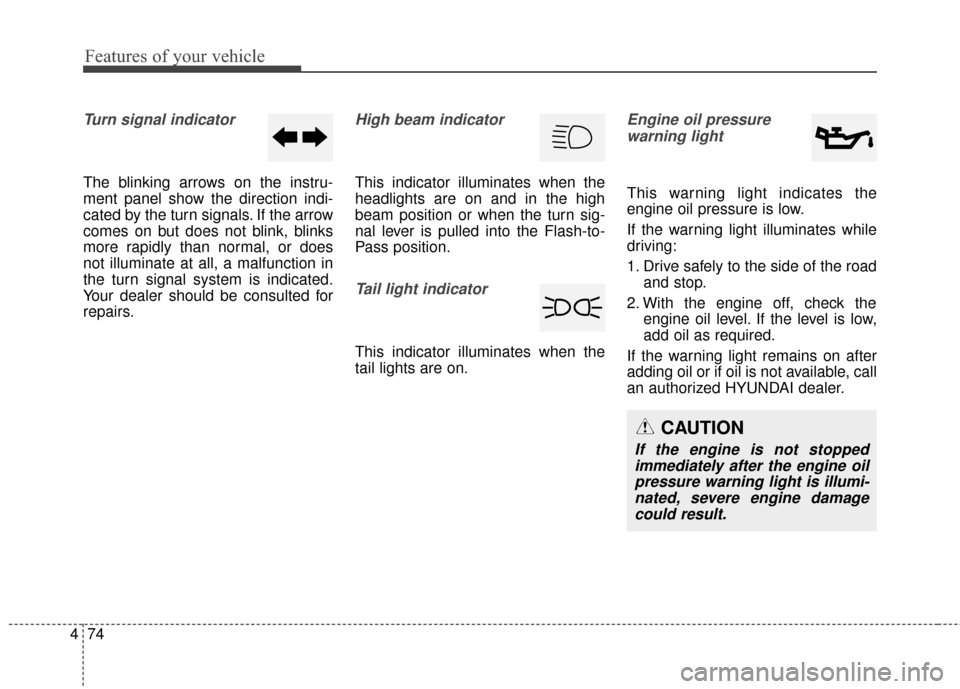
Turn signal indicator
The blinking arrows on the instru-
ment panel show the direction indi-
cated by the turn signals. If the arrow
comes on but does not blink, blinks
more rapidly than normal, or does
not illuminate at all, a malfunction in
the turn signal system is indicated.
Your dealer should be consulted for
repairs.
High beam indicator
This indicator illuminates when the
headlights are on and in the high
beam position or when the turn sig-
nal lever is pulled into the Flash-to-
Pass position.
Tail light indicator
This indicator illuminates when the
tail lights are on.
Engine oil pressure
warning light
This warning light indicates the
engine oil pressure is low.
If the warning light illuminates while
driving:
1. Drive safely to the side of the road and stop.
2. With the engine off, check the engine oil level. If the level is low,
add oil as required.
If the warning light remains on after
adding oil or if oil is not available, call
an authorized HYUNDAI dealer.
CAUTION
If the engine is not stopped immediately after the engine oilpressure warning light is illumi-nated, severe engine damagecould result.
Page 179 of 546
Features of your vehicle
92
4
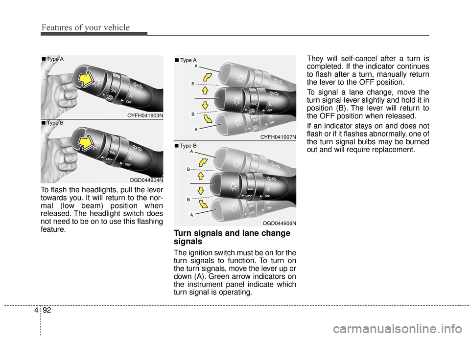
To flash the headlights, pull the lever
towards you. It will return to the nor-
mal (low beam) position when
released. The headlight switch does
not need to be on to use this flashing
feature.
Turn signals and lane change
signals
The ignition switch must be on for the
turn signals to function. To turn on
the turn signals, move the lever up or
down (A). Green arrow indicators on
the instrument panel indicate which
turn signal is operating. They will self-cancel after a turn is
completed. If the indicator continues
to flash after a turn, manually return
the lever to the OFF position.
To signal a lane change, move the
turn signal lever slightly and hold it in
position (B). The lever will return to
the OFF position when released.
If an indicator stays on and does not
flash or if it flashes abnormally, one of
the turn signal bulbs may be burned
out and will require replacement.
OYFH041903N
■
Type A
OGD044904N
■
Type B
OYFH041907N
■
Type A
OGD044906N
■
Type B