key battery Hyundai Elantra GT 2017 User Guide
[x] Cancel search | Manufacturer: HYUNDAI, Model Year: 2017, Model line: Elantra GT, Model: Hyundai Elantra GT 2017Pages: 493, PDF Size: 11.53 MB
Page 298 of 493

Driving your vehicle
65
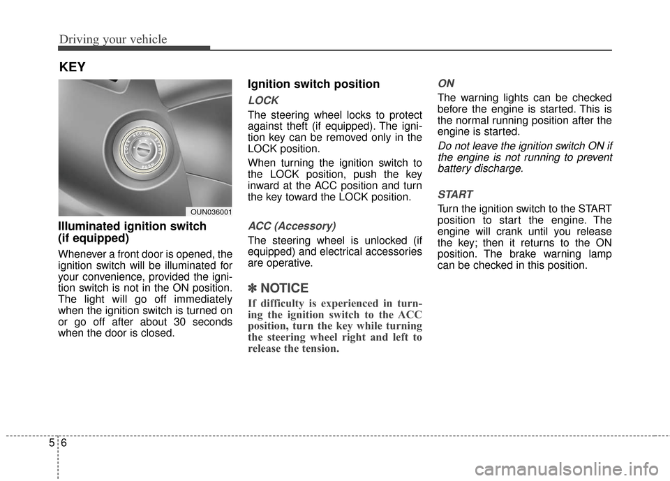
Illuminated ignition switch
(if equipped)
Whenever a front door is opened, the
ignition switch will be illuminated for
your convenience, provided the igni-
tion switch is not in the ON position.
The light will go off immediately
when the ignition switch is turned on
or go off after about 30 seconds
when the door is closed.
Ignition switch position
LOCK
The steering wheel locks to protect
against theft (if equipped). The igni-
tion key can be removed only in the
LOCK position.
When turning the ignition switch to
the LOCK position, push the key
inward at the ACC position and turn
the key toward the LOCK position.
ACC (Accessory)
The steering wheel is unlocked (if
equipped) and electrical accessories
are operative.
✽ ✽NOTICE
If difficulty is experienced in turn-
ing the ignition switch to the ACC
position, turn the key while turning
the steering wheel right and left to
release the tension.
ON
The warning lights can be checked
before the engine is started. This is
the normal running position after the
engine is started.
Do not leave the ignition switch ON if
the engine is not running to preventbattery discharge.
START
Turn the ignition switch to the START
position to start the engine. The
engine will crank until you release
the key; then it returns to the ON
position. The brake warning lamp
can be checked in this position.
KEY
OUN036001
Page 304 of 493

Driving your vehicle
12
5
4.Press the engine start/stop button.
It should be started without depress-
ing the accelerator.
5.Do not wait for the engine to warm
up while the vehicle remains sta-
tionary.
Start driving at moderate engine
speeds. (Steep accelerating and
decelerating should be avoided.) If the smart key is in the vehicle,
but it is not close to the driver’s
seat area, then the engine may not
start.
When the engine start/stop button is in the ACC or ON position, if any
door is open, the system checks
for the smart key. If the smart key is
not in the vehicle, and if all doors
are closed, the chime will sound for
about 5 seconds. Keep the smart
key in the vehicle, when using the
ACC position or if the vehicle
engine is on.
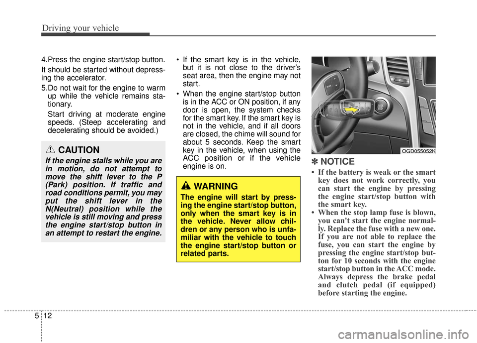
✽ ✽ NOTICE
• If the battery is weak or the smart
key does not work correctly, you
can start the engine by pressing
the engine start/stop button with
the smart key.
• When the stop lamp fuse is blown, you can't start the engine normal-
ly. Replace the fuse with a new one.
If you are not able to replace the
fuse, you can start the engine by
pressing the engine start/stop but-
ton for 10 seconds with the engine
start/stop button in the ACC mode.
Always depress the brake pedal
and clutch pedal (if equipped)
before starting the engine.
WARNING
The engine will start by press-
ing the engine start/stop button,
only when the smart key is in
the vehicle. Never allow chil-
dren or any person who is unfa-
miliar with the vehicle to touch
the engine start/stop button or
related parts.
OGD055052KCAUTION
If the engine stalls while you are
in motion, do not attempt tomove the shift lever to the P(Park) position. If traffic androad conditions permit, you mayput the shift lever in theN(Neutral) position while thevehicle is still moving and pressthe engine start/stop button inan attempt to restart the engine.
Page 437 of 493

761
Maintenance
If the headlights or other electrical
components do not work and the
fuses are OK, check the fuse panel
in the engine compartment. If a fuse
is open, it must be replaced.
If the headlights, fog lights, turn sig-
nal lights, position lights or interior
lights do not work and there is noth-
ing wrong with the bulbs, consult with
an authorized HYUNDAI dealer.
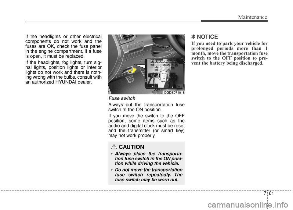
Fuse switch
Always put the transportation fuse
switch at the ON position.
If you move the switch to the OFF
position, some items such as the
audio and digital clock must be reset
and the transmitter (or smart key)
may not work properly.
✽ ✽NOTICE
If you need to park your vehicle for
prolonged periods more than 1
month, move the transportation fuse
switch to the OFF position to pre-
vent the battery being discharged.
CAUTION
Always place the transporta-
tion fuse switch in the ON posi-tion while driving the vehicle.
Do not move the transportation fuse switch repeatedly. Thefuse switch may be worn out.
OGDE071018
Page 489 of 493

Index
6I
Power outlet..............................................................4-128
Sunvisor ....................................................................4-12\
7
Interior light ..................................................................4-97
Interior overview ............................................................2-4
Jack and tools ................................................................6-14
Jump starting ..................................................................6-5
Key ........................................................................\
..........5-6
Keys ........................................................................\
........4-4
Label Air bag warning label ................................................3-68
Refrigerant label ..........................................................8-9
Jack label ....................................................................6-21\
Tire sidewall labeling ................................................7-50
Tire specification and pressure label ............................8-9
Vehicle certification label ............................................8-8
LCD display warning ....................................................4-82
Light bulbs ....................................................................7-72\
Lighting ........................................................................\
4-88 Battery saver function ................................................4-88 Daytime running light ................................................4-89
Headlamp delay ..........................................................4-88
Headlamp welcome function......................................4-88
Lower anchor ................................................................3-38
Lubricants and capacities ................................................8-5
Luggage net ................................................................4-124
Maintenance Explanation of scheduled maintenance items ............7-23
Maintenance services ..................................................7-4
Maintenance under severe usage conditions ..............7-21
Normal maintenance schedule ....................................7-9
Scheduled maintenance service....................................7-8
Tire maintenance ........................................................7-49
Maintenance schedule ....................................................7-8 Maintenance under severe usage conditions ..............7-21
Normal maintenance schedule ....................................7-9
Maintenance services ......................................................7-3
Manual climate control system ..................................4-101 Air conditioning ......................................................4-107
Climate control air filter ..........................................4-109
Heating and air conditioning ....................................4-102
Manual transaxle ..........................................................5-14
Manual transaxle shift indicator....................................4-60
Mirrors ........................................................................\
..4-48 Blue link center ..........................................................4-48
M
K
L
J