Hyundai Elantra GT 2017 Owner's Manual
Manufacturer: HYUNDAI, Model Year: 2017, Model line: Elantra GT, Model: Hyundai Elantra GT 2017Pages: 493, PDF Size: 11.53 MB
Page 441 of 493
765
Maintenance
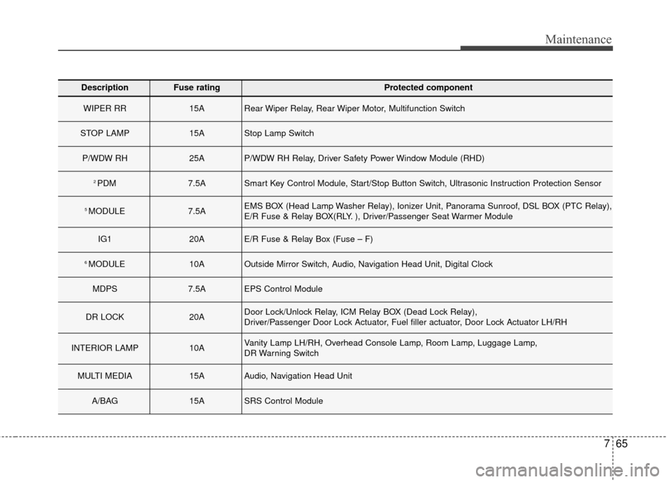
DescriptionFuse ratingProtected component
WIPER RR15ARear Wiper Relay, Rear Wiper Motor, Multifunction Switch
STOP LAMP15AStop Lamp Switch
P/WDW RH25AP/WDW RH Relay, Driver Safety Power Window Module (RHD)
2 PDM7.5ASmart Key Control Module, Start/Stop Button Switch, Ultrasonic Instruction Protection Sensor
5 MODULE7.5AEMS BOX (Head Lamp Washer Relay), Ionizer Unit, Panorama Sunroof, DSL BOX (PTC Relay),
E/R Fuse & Relay BOX(RLY. ), Driver/Passenger Seat Warmer Module
IG120AE/R Fuse & Relay Box (Fuse – F)
6 MODULE10AOutside Mirror Switch, Audio, Navigation Head Unit, Digital Clock
MDPS7.5AEPS Control Module
DR LOCK20ADoor Lock/Unlock Relay, ICM Relay BOX (Dead Lock Relay),
Driver/Passenger Door Lock Actuator, Fuel filler actuator, Door Lock Actuator LH/RH
INTERIOR LAMP10AVanity Lamp LH/RH, Overhead Console Lamp, Room Lamp, Luggage Lamp,
DR Warning Switch
MULTI MEDIA15AAudio, Navigation Head Unit
A/BAG15ASRS Control Module
Page 442 of 493
Maintenance
66
7
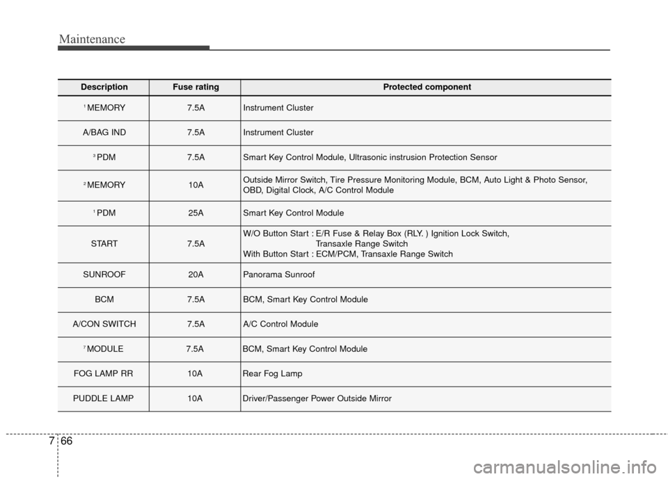
DescriptionFuse ratingProtected component
1 MEMORY7.5AInstrument Cluster
A/BAG IND7.5AInstrument Cluster
3 PDM7.5ASmart Key Control Module, Ultrasonic instrusion Protection Sensor
2 MEMORY10AOutside Mirror Switch, Tire Pressure Monitoring Module, BCM, Auto Light & Photo Sensor,
OBD, Digital Clock, A/C Control Module
1 PDM25ASmart Key Control Module
START7.5AW/O Button Start : E/R Fuse & Relay Box (RLY. ) Ignition Lock Switch,
Transaxle Range Switch
With Button Start : ECM/PCM, Transaxle Range Switch
SUNROOF20APanorama Sunroof
BCM7.5ABCM, Smart Key Control Module
A/CON SWITCH7.5AA/C Control Module
7 MODULE7.5ABCM, Smart Key Control Module
FOG LAMP RR10ARear Fog Lamp
PUDDLE LAMP10ADriver/Passenger Power Outside Mirror
Page 443 of 493
767
Maintenance
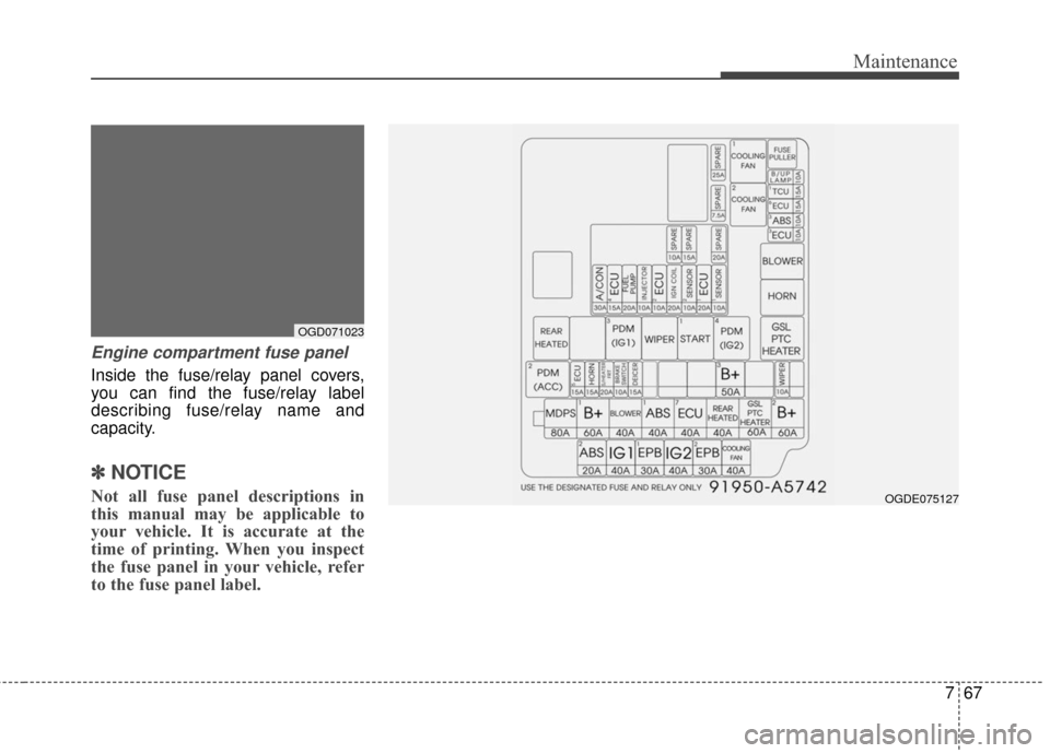
Engine compartment fuse panel
Inside the fuse/relay panel covers,
you can find the fuse/relay label
describing fuse/relay name and
capacity.
✽ ✽NOTICE
Not all fuse panel descriptions in
this manual may be applicable to
your vehicle. It is accurate at the
time of printing. When you inspect
the fuse panel in your vehicle, refer
to the fuse panel label.
OGD071023
OGDE075127
Page 444 of 493
Maintenance
68
7
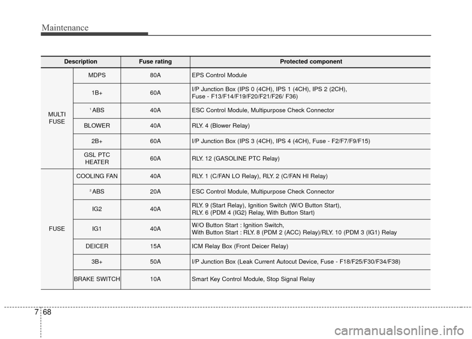
DescriptionFuse ratingProtected component
MULTI
FUSE
MDPS80AEPS Control Module
1B+60AI/P Junction Box (IPS 0 (4CH), IPS 1 (4CH), IPS 2 (2CH),
Fuse - F13/F14/F19/F20/F21/F26/ F36)
1 ABS40AESC Control Module, Multipurpose Check Connector
BLOWER40ARLY. 4 (Blower Relay)
2B+60AI/P Junction Box (IPS 3 (4CH), IPS 4 (4CH), Fuse - F2/F7/F9/F15)
GSL PTC HEATER60ARLY. 12 (GASOLINE PTC Relay)
FUSE
COOLING FAN40ARLY. 1 (C/FAN LO Relay), RLY. 2 (C/FAN HI Relay)
2 ABS20AESC Control Module, Multipurpose Check Connector
IG240ARLY. 9 (Start Relay), Ignition Switch (W/O Button Start),
RLY. 6 (PDM 4 (IG2) Relay, With Button Start)
IG140AW/O Button Start : Ignition Switch,
With Button Start : RLY. 8 (PDM 2 (ACC) Relay)/RLY. 10 (PDM 3 (IG1) Relay
DEICER15AICM Relay Box (Front Deicer Relay)
3B+50AI/P Junction Box (Leak Current Autocut Device, Fuse - F18/F25/F30/F34/F38)
BRAKE SWITCH10ASmart Key Control Module, Stop Signal Relay
Page 445 of 493
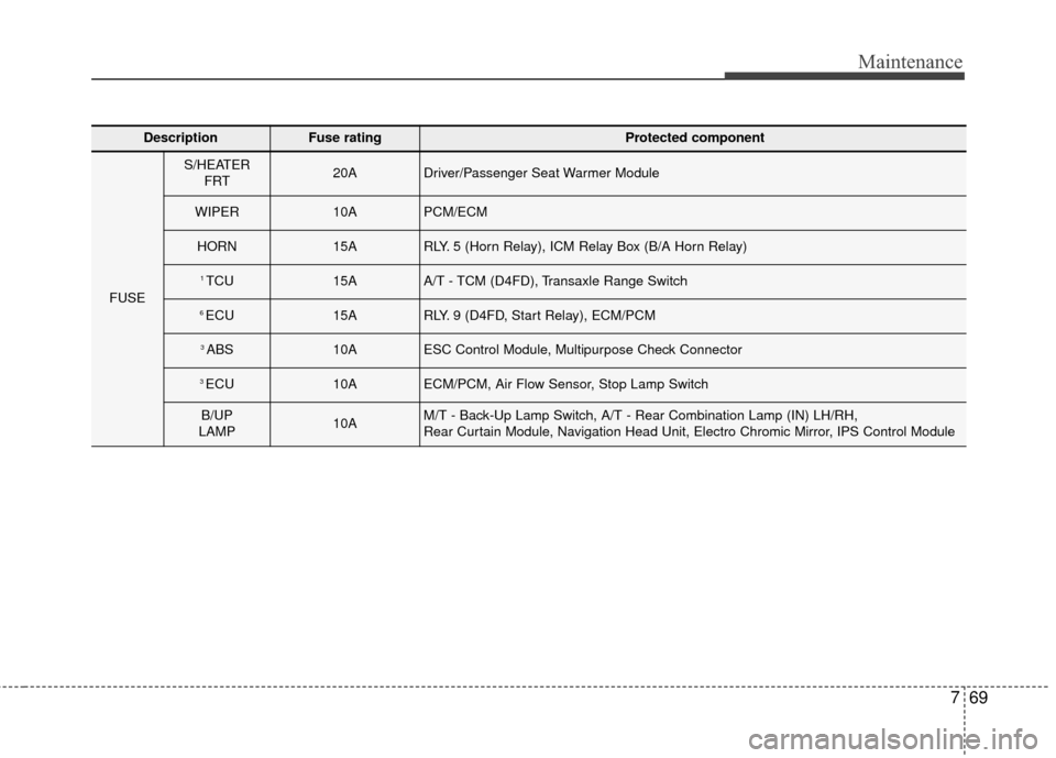
769
Maintenance
DescriptionFuse ratingProtected component
FUSE
S/HEATER FRT20ADriver/Passenger Seat Warmer Module
WIPER10APCM/ECM
HORN15ARLY. 5 (Horn Relay), ICM Relay Box (B/A Horn Relay)
1 TCU15AA/T - TCM (D4FD), Transaxle Range Switch
6 ECU15ARLY. 9 (D4FD, Start Relay), ECM/PCM
3 ABS10AESC Control Module, Multipurpose Check Connector
3 ECU10AECM/PCM, Air Flow Sensor, Stop Lamp Switch
B/UP
LAMP10AM/T - Back-Up Lamp Switch, A/T - Rear Combination Lamp (IN) LH/RH,
Rear Curtain Module, Navigation Head Unit, Electro Chromic Mirror, IPS Control Module
Page 446 of 493
Maintenance
70
7
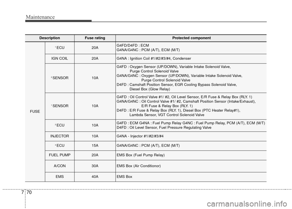
DescriptionFuse ratingProtected component
FUSE
1 ECU20AG4FD/D4FD : ECM
G4NA/G4NC : PCM (A/T), ECM (M/T)
IGN COIL20AG4NA : Ignition Coil #1/#2/#3/#4, Condenser
2 SENSOR10A
G4FD : Oxygen Sensor (UP/DOWN), Variable Intake Solenoid Valve,
Purge Control Solenoid Valve
G4NA/G4NC : Oxygen Sensor (UP/DOWN), Variable Intake Solenoid Valve, Purge Control Solenoid Valve
D4FD : Camshaft Position Sensor, EGR Cooling Bypass Solenoid Valve, Diesel Box (Glow Relay)
1 SENSOR10A
G4FD : Oil Control Valve #1/ #2, Oil Level Sensor, E/R Fuse & Relay Box (RLY. 1)
G4NA/G4NC : Oil Control Valve #1/ #2, Camshaft Position Sensor (Intake/Exhaust), E/R Fuse & Relay Box (RLY. 1)
D4FD : E/R Fuse & Relay Box (RLY. 1), Diesel Box (PTC Heater Relay#1), Lambda Sensor, VGT Control Solenoid Valve
2 ECU10AG4FD : ECM G4NA : Fuel Pump Relay G4NC : Fuel Pump Relay, PCM (A/T), ECM (M/T)
D4FD : Oil Level Sensor, Fuel Pressure Regulating Valve
INJECTOR10AG4NA - Injector #1/#2/#3/#4
4 ECU15AG4NA/G4NC : PCM (A/T), ECM (M/T)
FUEL PUMP20AEMS Box (Fuel Pump Relay)
A/CON30AEMS Box (Air Conditionor)
EMS40AEMS Box
Page 447 of 493
771
Maintenance
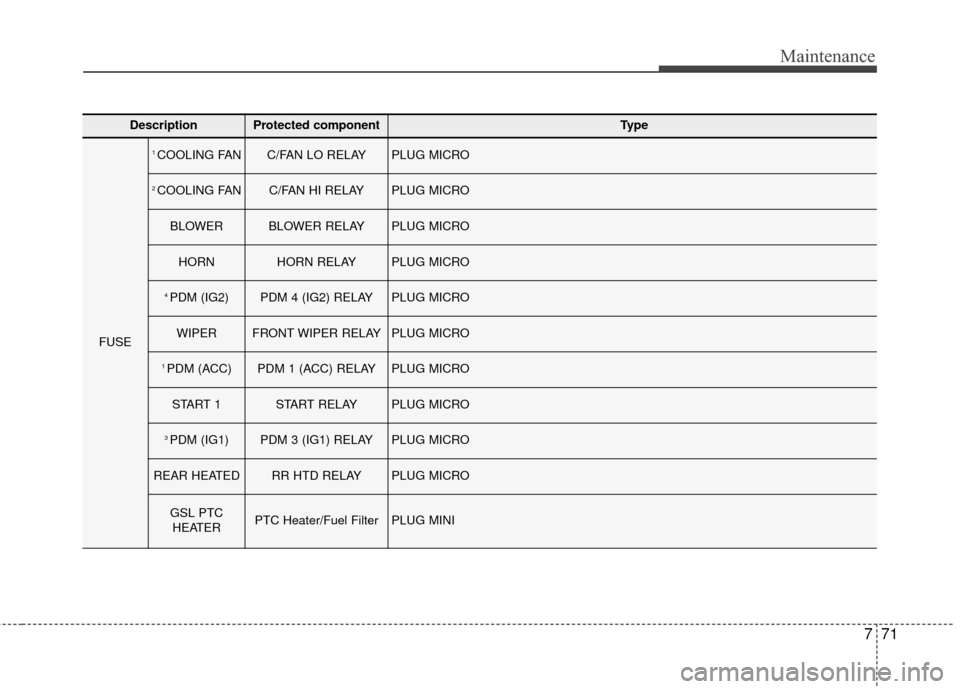
DescriptionProtected componentType
FUSE
1 COOLING FANC/FAN LO RELAY PLUG MICRO
2 COOLING FANC/FAN HI RELAY PLUG MICRO
BLOWERBLOWER RELAY PLUG MICRO
HORNHORN RELAY PLUG MICRO
4 PDM (IG2)PDM 4 (IG2) RELAY PLUG MICRO
WIPERFRONT WIPER RELAY PLUG MICRO
1 PDM (ACC)PDM 1 (ACC) RELAY PLUG MICRO
START 1START RELAY PLUG MICRO
3 PDM (IG1)PDM 3 (IG1) RELAY PLUG MICRO
REAR HEATEDRR HTD RELAY PLUG MICRO
GSL PTCHEATERPTC Heater/Fuel FilterPLUG MINI
Page 448 of 493
Maintenance
72
7
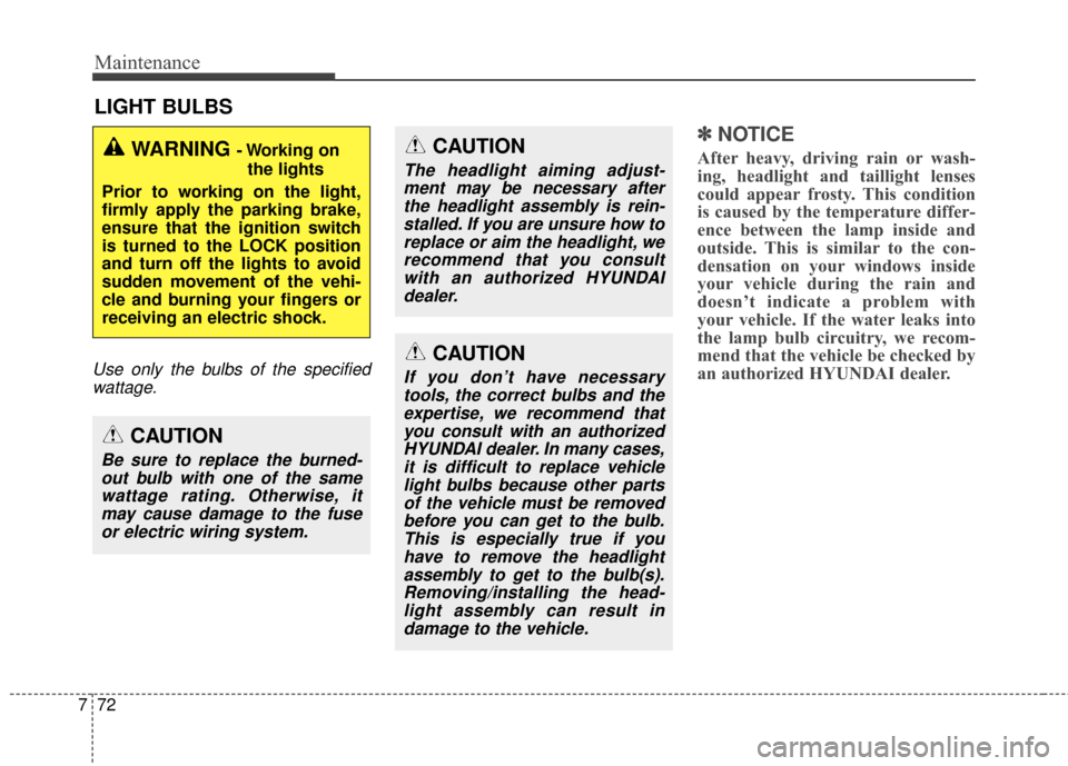
LIGHT BULBS
Use only the bulbs of the specified
wattage.
✽
✽ NOTICE
After heavy, driving rain or wash-
ing, headlight and taillight lenses
could appear frosty. This condition
is caused by the temperature differ-
ence between the lamp inside and
outside. This is similar to the con-
densation on your windows inside
your vehicle during the rain and
doesn’t indicate a problem with
your vehicle. If the water leaks into
the lamp bulb circuitry, we recom-
mend that the vehicle be checked by
an authorized HYUNDAI dealer.WARNING - Working on
the lights
Prior to working on the light,
firmly apply the parking brake,
ensure that the ignition switch
is turned to the LOCK position
and turn off the lights to avoid
sudden movement of the vehi-
cle and burning your fingers or
receiving an electric shock.
CAUTION
Be sure to replace the burned- out bulb with one of the samewattage rating. Otherwise, itmay cause damage to the fuseor electric wiring system.
CAUTION
The headlight aiming adjust-ment may be necessary afterthe headlight assembly is rein-stalled. If you are unsure how toreplace or aim the headlight, werecommend that you consultwith an authorized HYUNDAIdealer.
CAUTION
If you don’t have necessarytools, the correct bulbs and theexpertise, we recommend thatyou consult with an authorizedHYUNDAI dealer. In many cases,it is difficult to replace vehiclelight bulbs because other partsof the vehicle must be removedbefore you can get to the bulb.This is especially true if youhave to remove the headlightassembly to get to the bulb(s).Removing/installing the head-light assembly can result indamage to the vehicle.
Page 449 of 493
773
Maintenance
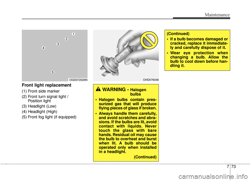
Front light replacement
(1) Front side marker
(2) Front turn signal light / Position light
(3) Headlight (Low)
(4) Headlight (High)
(5) Front fog light (if equipped)WARNING - Halogen
bulbs
Halogen bulbs contain pres- surized gas that will produce
flying pieces of glass if broken.
Always handle them carefully, and avoid scratches and abra-
sions. If the bulbs are lit, avoid
contact with liquids. Never
touch the glass with bare
hands. Residual oil may cause
the bulb to overheat and burst
when lit. A bulb should be
operated only when installed
in a headlight.
(Continued)
OHD076046OGD072026N
(Continued)
If a bulb becomes damaged orcracked, replace it immediate-
ly and carefully dispose of it.
Wear eye protection when changing a bulb. Allow the
bulb to cool down before han-
dling it.
Page 450 of 493
Maintenance
74
7
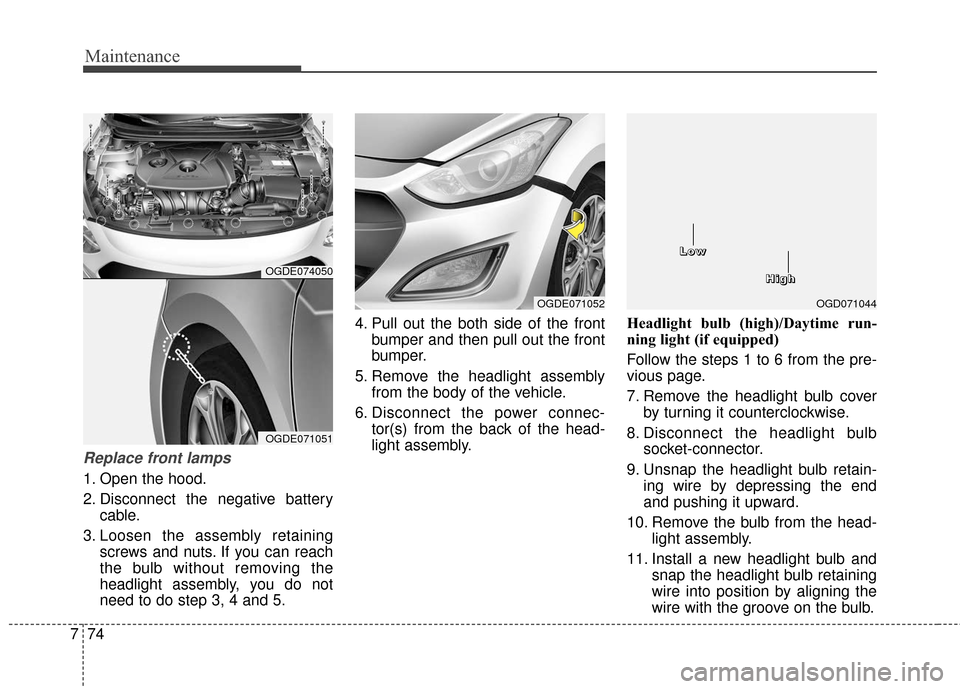
Replace front lamps
1. Open the hood.
2. Disconnect the negative battery
cable.
3. Loosen the assembly retaining screws and nuts. If you can reach
the bulb without removing the
headlight assembly, you do not
need to do step 3, 4 and 5. 4. Pull out the both side of the front
bumper and then pull out the front
bumper.
5. Remove the headlight assembly from the body of the vehicle.
6. Disconnect the power connec- tor(s) from the back of the head-
light assembly. Headlight bulb (high)/Daytime run-
ning light (if equipped)
Follow the steps 1 to 6 from the pre-
vious page.
7. Remove the headlight bulb cover
by turning it counterclockwise.
8. Disconnect the headlight bulb socket-connector.
9. Unsnap the headlight bulb retain- ing wire by depressing the end
and pushing it upward.
10. Remove the bulb from the head- light assembly.
11. Install a new headlight bulb and snap the headlight bulb retaining
wire into position by aligning the
wire with the groove on the bulb.
OGDE071052
OGDE074050
OGDE071051
OGD071044
H
H
H
H
i
i
i
i
g
g
g
g
h
h
h
h
L
L
L
L
o
o
o
o
w
w
w
w