instrument panel Hyundai Elantra GT 2018 User Guide
[x] Cancel search | Manufacturer: HYUNDAI, Model Year: 2018, Model line: Elantra GT, Model: Hyundai Elantra GT 2018Pages: 478, PDF Size: 13.64 MB
Page 167 of 478
3-82
Convenient features of your vehicle
• Do not cover or spill anything on the sensor (1) located in front of
the instrument panel.
Do not clean the sensor using a window cleaner, the cleanser may
leave a light film which could
interfere with sensor operation.
If your vehicle has window tint or other types of metallic coat-
ing on the front windshield, the
AUTO light system may not work
properly.
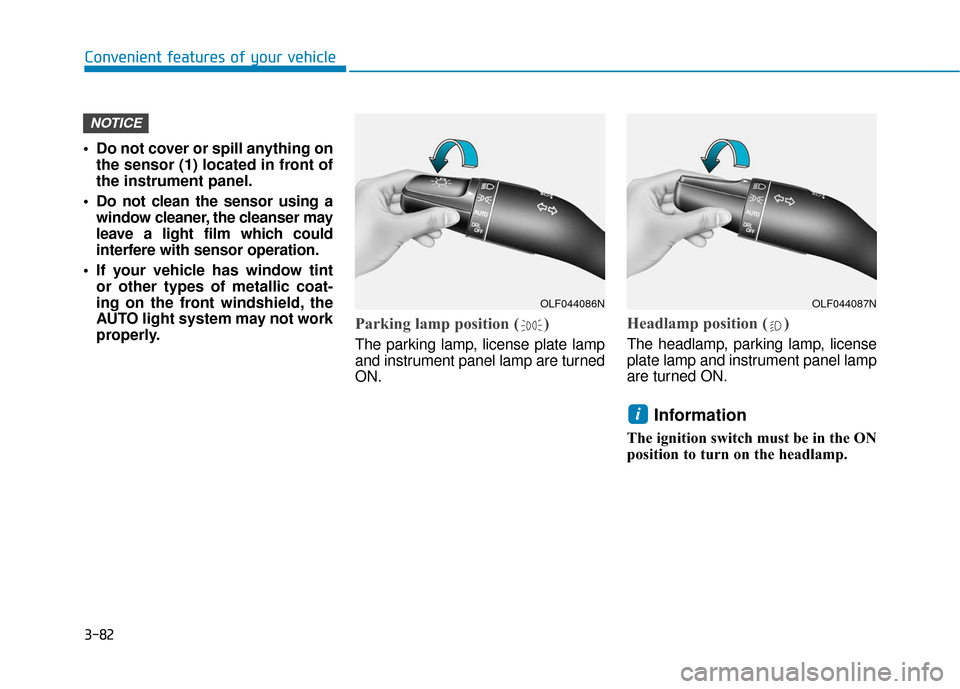
Parking lamp position ( )
The parking lamp, license plate lamp
and instrument panel lamp are turned
ON.
Headlamp position ( )
The headlamp, parking lamp, license
plate lamp and instrument panel lamp
are turned ON.
Information
The ignition switch must be in the ON
position to turn on the headlamp.
i
NOTICE
OLF044086NOLF044087N
Page 183 of 478
3-98
Convenient features of your vehicle
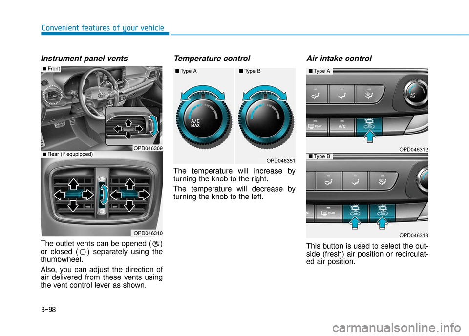
Instrument panel vents
The outlet vents can be opened ( )
or closed ( ) separately using the
thumbwheel.
Also, you can adjust the direction of
air delivered from these vents using
the vent control lever as shown.
Temperature control
The temperature will increase by
turning the knob to the right.
The temperature will decrease by
turning the knob to the left.
Air intake control
This button is used to select the out-
side (fresh) air position or recirculat-
ed air position.
OPD046351
OPD046312
OPD046313
■Type A
■Type B
■Type A■Type B
OPD046310
■ Rear (if equpipped)
■Front
OPD046309
Page 193 of 478
3-108
Convenient features of your vehicle
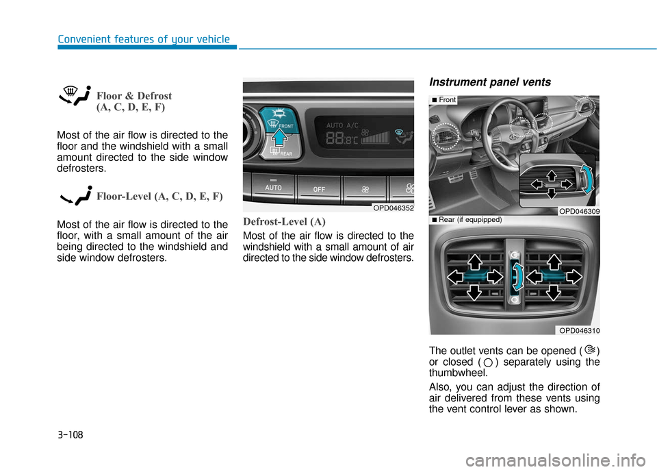
Floor & Defrost
(A, C, D, E, F)
Most of the air flow is directed to the
floor and the windshield with a small
amount directed to the side window
defrosters.
Floor-Level (A, C, D, E, F)
Most of the air flow is directed to the
floor, with a small amount of the air
being directed to the windshield and
side window defrosters.Defrost-Level (A)
Most of the air flow is directed to the
windshield with a small amount of air
directed to the side window defrosters.
Instrument panel vents
The outlet vents can be opened ( )
or closed ( ) separately using the
thumbwheel.
Also, you can adjust the direction of
air delivered from these vents using
the vent control lever as shown.
OPD046352
OPD046310
■ Rear (if equpipped)
■Front
OPD046309
Page 204 of 478
3-119
Convenient features of your vehicle
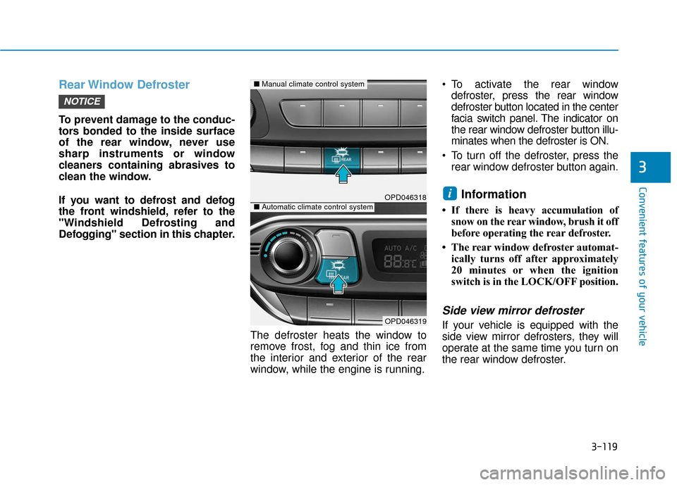
Rear Window Defroster
To prevent damage to the conduc-
tors bonded to the inside surface
of the rear window, never use
sharp instruments or window
cleaners containing abrasives to
clean the window.
If you want to defrost and defog
the front windshield, refer to the
"Windshield Defrosting and
Defogging" section in this chapter.The defroster heats the window to
remove frost, fog and thin ice from
the interior and exterior of the rear
window, while the engine is running. To activate the rear window
defroster, press the rear window
defroster button located in the center
facia switch panel. The indicator on
the rear window defroster button illu-
minates when the defroster is ON.
To turn off the defroster, press the rear window defroster button again.
Information
• If there is heavy accumulation ofsnow on the rear window, brush it off
before operating the rear defroster.
• The rear window defroster automat- ically turns off after approximately
20 minutes or when the ignition
switch is in the LOCK/OFF position.
Side view mirror defroster
If your vehicle is equipped with the
side view mirror defrosters, they will
operate at the same time you turn on
the rear window defroster.
i
NOTICE
33
OPD046318
OPD046319
■ Manual climate control system
■Automatic climate control system
Page 222 of 478
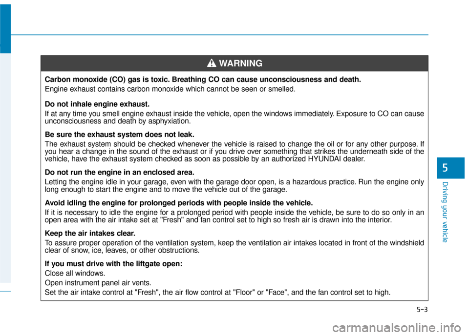
5-3
Driving your vehicle
5
Carbon monoxide (CO) gas is toxic. Breathing CO can cause unconsciousness and death.
Engine exhaust contains carbon monoxide which cannot be seen or smelled.
Do not inhale engine exhaust.
If at any time you smell engine exhaust inside the vehicle, open the windows immediately. Exposure to CO can cause
unconsciousness and death by asphyxiation.
Be sure the exhaust system does not leak.
The exhaust system should be checked whenever the vehicle is raised to change the oil or for any other purpose. If
you hear a change in the sound of the exhaust or if you drive over something that strikes the underneath side of the
vehicle, have the exhaust system checked as soon as possible by an authorized HYUNDAI dealer.
Do not run the engine in an enclosed area.
Letting the engine idle in your garage, even with the garage door open, is a hazardous practice. Run the engine only
long enough to start the engine and to move the vehicle out of the garage.
Avoid idling the engine for prolonged periods with people inside the vehicle.
If it is necessary to idle the engine for a prolonged period with people inside the vehicle, be sure to do so only in an
open area with the air intake set at "Fresh" and fan control set to high so fresh air is drawn into the interior.
Keep the air intakes clear.
To assure proper operation of the ventilation system, keep the ventilation air intakes located in front of the windshield
clear of snow, ice, leaves, or other obstructions.
If you must drive with the liftgate open:
Close all windows.
Open instrument panel air vents.
Set the air intake control at "Fresh", the air flow control at "Floor" or "Face", and the fan control set to high.
WARNING
Page 223 of 478
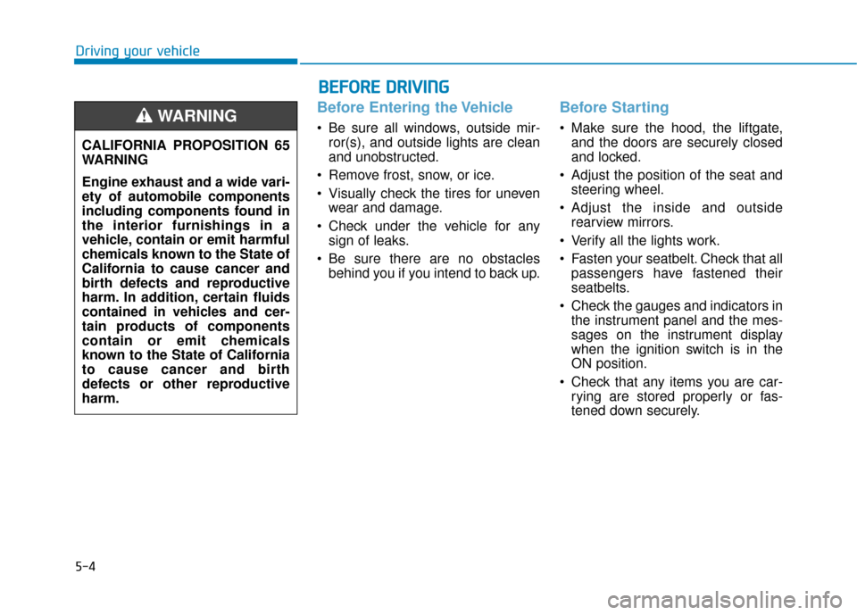
5-4
Driving your vehicle
Before Entering the Vehicle
• Be sure all windows, outside mir-ror(s), and outside lights are clean
and unobstructed.
Remove frost, snow, or ice.
Visually check the tires for uneven wear and damage.
Check under the vehicle for any sign of leaks.
Be sure there are no obstacles behind you if you intend to back up.
Before Starting
Make sure the hood, the liftgate,and the doors are securely closed
and locked.
Adjust the position of the seat and steering wheel.
Adjust the inside and outside rearview mirrors.
Verify all the lights work.
Fasten your seatbelt. Check that all passengers have fastened their
seatbelts.
Check the gauges and indicators in the instrument panel and the mes-
sages on the instrument display
when the ignition switch is in the
ON position.
Check that any items you are car- rying are stored properly or fas-
tened down securely.
CALIFORNIA PROPOSITION 65
WARNING
Engine exhaust and a wide vari-
ety of automobile components
including components found in
the interior furnishings in a
vehicle, contain or emit harmful
chemicals known to the State of
California to cause cancer and
birth defects and reproductive
harm. In addition, certain fluids
contained in vehicles and cer-
tain products of components
contain or emit chemicals
known to the State of California
to cause cancer and birth
defects or other reproductive
harm.WARNING
B B
E
EF
FO
O R
RE
E
D
D R
RI
IV
V I
IN
N G
G
Page 294 of 478
5-75
Driving your vehicle
5
(Continued)
The system detects lane lines
and controls the steering
wheel by a camera, therefore,
if the lane lines are hard to
detect, the system may not
work properly.
Please refer to "Limitations of
the system".
Do not remove or damage the
related parts of LKAS.
You may not hear a warning
sound of LKAS because of
excessive audio sound.
Do not place objects on the
dashboard that reflects light
such as mirrors, white paper,
etc. The system may malfunc-
tion if the sunlight is reflected.(Continued)
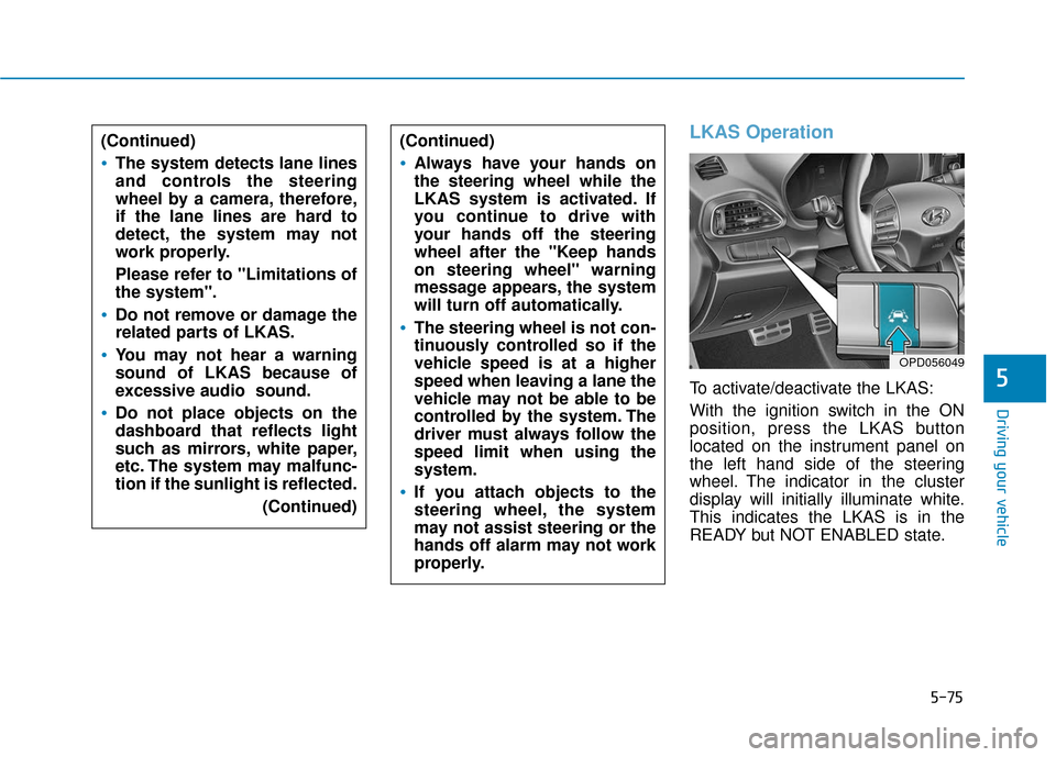
LKAS Operation
To activate/deactivate the LKAS:
With the ignition switch in the ON
position, press the LKAS button
located on the instrument panel on
the left hand side of the steering
wheel. The indicator in the cluster
display will initially illuminate white.
This indicates the LKAS is in the
READY but NOT ENABLED state.
(Continued)
Always have your hands on
the steering wheel while the
LKAS system is activated. If
you continue to drive with
your hands off the steering
wheel after the "Keep hands
on steering wheel" warning
message appears, the system
will turn off automatically.
The steering wheel is not con-
tinuously controlled so if the
vehicle speed is at a higher
speed when leaving a lane the
vehicle may not be able to be
controlled by the system. The
driver must always follow the
speed limit when using the
system.
If you attach objects to the
steering wheel, the system
may not assist steering or the
hands off alarm may not work
properly.
OPD056049
Page 363 of 478
7
Tires and Wheels .................................................7-38
Tire Care ........................................................................\
....7-38
Recommended Cold Tire Inflation Pressures ...........7-39
Check Tire Inflation Pressure ......................................7-40
Tire Rotation...................................................................\
..7-40
Wheel Alignment and Tire Balance ............................7-41
Tire Replacement ............................................................7-42
Wheel Replacement ........................................................7-43
Tire Traction .....................................................................7-4\
3
Tire Maintenance ............................................................7-43
Tire Sidewall Labeling ....................................................7-43
Tire Terminology and Definitions................................7-47
All Season Tires ...............................................................7-50
Summer Tires ...................................................................7-50
Snow Tires ........................................................................\
7-51
Radial-Ply Tires ...............................................................7-51
Low Aspect Ratio Tires..................................................7-51
Fuses ......................................................................7-\
53
Instrument Panel Fuse Replacement..........................7-54
Engine Compartment Panel Fuse Replacement.......7-55
Fuse/Relay Panel Description ......................................7-57
Light Bulbs ............................................................7-67
Headlamp, Parking Lamp, Daytime Running Light,
Turn Signal Lamp and Side Marker ............................7-67
Side Repeater Lamp Replacement ..............................7-70
Rear Combination Light Bulb Replacement ..............7-71
High Mounted Stop Lamp Replacement ....................7-75
License Plate Light Bulb Replacement ......................7-76
Interior Light Bulb Replacement .................................7-76
Appearance care ..................................................7-78
Exterior Care ....................................................................7-78\
Interior Care .....................................................................7-8\
2
Emission Control System ....................................7-85
Crankcase Emission Control System ..........................7-85
Evaporative Emission Control System Including
Onboard Refueling Vapor Recovery (ORVR)............7-85
Exhaust Emission Control System ..............................7-86
California Perchlorate Notice.............................7-89
Page 415 of 478
7-54
Maintenance
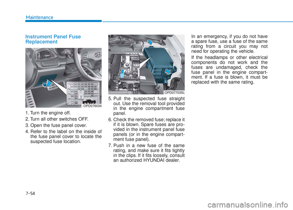
Instrument Panel Fuse
Replacement
1. Turn the engine off.
2. Turn all other switches OFF.
3. Open the fuse panel cover.
4. Refer to the label on the inside ofthe fuse panel cover to locate the
suspected fuse location. 5. Pull the suspected fuse straight
out. Use the removal tool provided
in the engine compartment fuse
panel.
6. Check the removed fuse; replace it if it is blown. Spare fuses are pro-
vided in the instrument panel fuse
panels (or in the engine compart-
ment fuse panel).
7. Push in a new fuse of the same rating, and make sure it fits tightly
in the clips. If it fits loosely, consult
an authorized HYUNDAI dealer. In an emergency, if you do not have
a spare fuse, use a fuse of the same
rating from a circuit you may not
need for operating the vehicle.
If the headlamps or other electrical
components do not work and the
fuses are undamaged, check the
fuse panel in the engine compart-
ment. If a fuse is blown, it must be
replaced with the same rating.
OPD077035L
OPD076034
Page 418 of 478
7-57
7
Maintenance
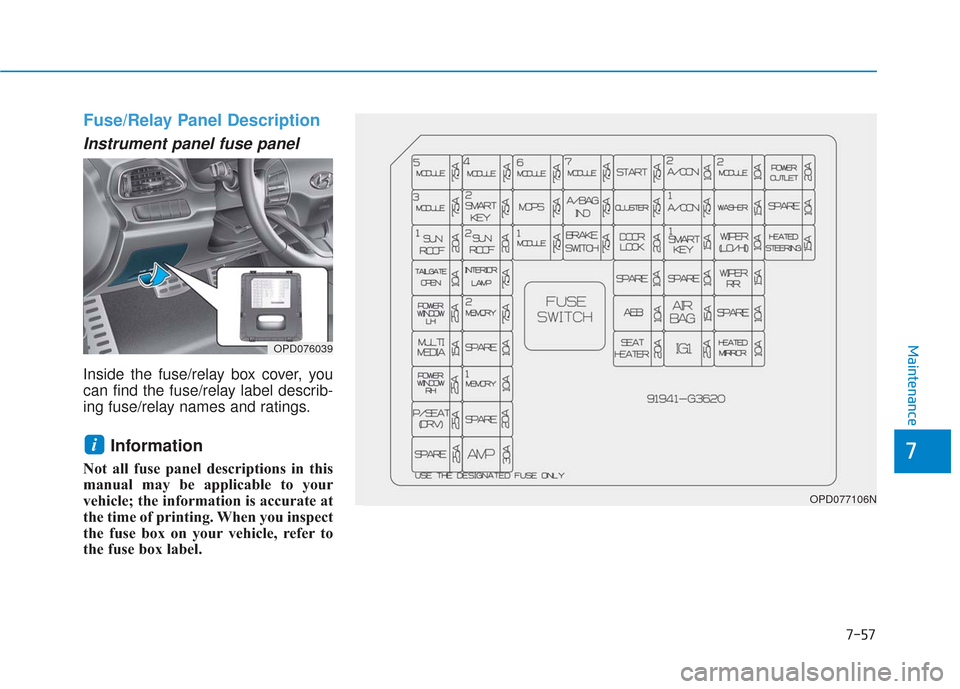
Fuse/Relay Panel Description
Instrument panel fuse panel
Inside the fuse/relay box cover, you
can find the fuse/relay label describ-
ing fuse/relay names and ratings.
Information
Not all fuse panel descriptions in this
manual may be applicable to your
vehicle; the information is accurate at
the time of printing. When you inspect
the fuse box on your vehicle, refer to
the fuse box label.
i
OPD076039
OPD077106N