engine Hyundai Elantra GT 2018 Repair Manual
[x] Cancel search | Manufacturer: HYUNDAI, Model Year: 2018, Model line: Elantra GT, Model: Hyundai Elantra GT 2018Pages: 478, PDF Size: 13.64 MB
Page 200 of 478
3-115
Convenient features of your vehicle
3
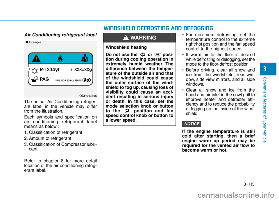
Air Conditioning refrigerant label
The actual Air Conditioning refriger-
ant label in the vehicle may differ
from the illustration.
Each symbols and specification on
air conditioning refrigerant label
means as below :
1. Classification of refrigerant
2. Amount of refrigerant
3. Classification of Compressor lubri-cant
Refer to chapter 8 for more detail
location of the air conditioning refrig-
erant label. For maximum defrosting, set the
temperature control to the extreme
right/hot position and the fan speed
control to the highest speed.
If warm air to the floor is desired while defrosting or defogging, set the
mode to the floor-defrost position.
Before driving, clear all snow and ice from the windshield, rear win-
dow, side view mirrors, and all side
windows.
Clear all snow and ice from the hood and air inlet in the cowl grill to
improve heater and defroster effi-
ciency and to reduce the probability
of fogging up the inside of the wind-
shield.
If the engine temperature is still
cold after starting, then a brief
engine warm up period may be
required for the vented air flow to
become warm or hot.
NOTICE
ODH043366
■ Example
W
WI
IN
N D
DS
SH
H I
IE
E L
LD
D
D
D E
EF
FR
R O
O S
ST
T I
IN
N G
G
A
A N
N D
D
D
D E
EF
FO
O G
GG
GI
IN
N G
G
Windshield heating
Do not use the or posi-
tion during cooling operation in
extremely humid weather. The
difference between the temper-
ature of the outside air and that
of the windshield could cause
the outer surface of the wind-
shield to fog up, causing loss of
visibility could cause an acci-
dent resulting in serious injury
or death. In this case, set the
mode selection knob or button
to the position and fan
speed control knob or button to
a lower speed.
WARNING
Page 204 of 478
3-119
Convenient features of your vehicle
Rear Window Defroster
To prevent damage to the conduc-
tors bonded to the inside surface
of the rear window, never use
sharp instruments or window
cleaners containing abrasives to
clean the window.
If you want to defrost and defog
the front windshield, refer to the
"Windshield Defrosting and
Defogging" section in this chapter.The defroster heats the window to
remove frost, fog and thin ice from
the interior and exterior of the rear
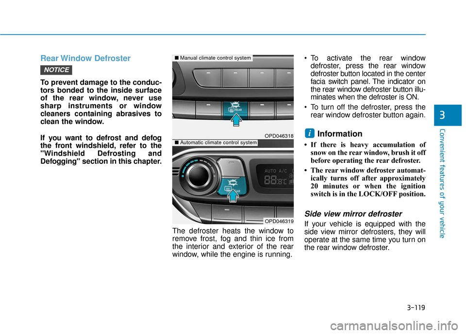
window, while the engine is running. To activate the rear window
defroster, press the rear window
defroster button located in the center
facia switch panel. The indicator on
the rear window defroster button illu-
minates when the defroster is ON.
To turn off the defroster, press the rear window defroster button again.
Information
• If there is heavy accumulation ofsnow on the rear window, brush it off
before operating the rear defroster.
• The rear window defroster automat- ically turns off after approximately
20 minutes or when the ignition
switch is in the LOCK/OFF position.
Side view mirror defroster
If your vehicle is equipped with the
side view mirror defrosters, they will
operate at the same time you turn on
the rear window defroster.
i
NOTICE
33
OPD046318
OPD046319
■ Manual climate control system
■Automatic climate control system
Page 205 of 478
3-120
Convenient features of your vehicle
C
CL
LI
IM
M A
AT
TE
E
C
C O
O N
NT
TR
R O
O L
L
A
A D
DD
DI
IT
T I
IO
O N
NA
AL
L
F
F E
E A
A T
TU
U R
RE
ES
S
(
( I
IF
F
E
E Q
Q U
UI
IP
P P
PE
ED
D )
)
Cluster ionizer (if equipped)
When the ignition switch is in the ON
position, the clean air function turns
on automatically.
Also, the clean air function turns off
automatically, when the ignition
switch is in the OFF position.
Automatic Ventilation
(if equipped)
When the ignition switch is in the ON
position or when the engine is run-
ning and temperature is below 59°F
(15°C) with the recirculated air posi-
tion selected more than five minutes,
the air intake position will automati-
cally change to the outside (fresh) air
position.
To cancel or reset the Automatic
Ventilation
When the air conditioning system is
on, select Face Level mode and
while pressing the A/C button, press
the recirculated air position button
five times within three seconds.
When the automatic ventilation is set,
the air intake control button (recircu-
lated air position) indicator will blink 6
times. When canceled, the air intake
control button (recirculated air posi-
tion) indicator will blink 3 times.
Sunroof Inside Air
Recirculation (if equipped)
When the heater or air conditioning
system is on with the sunroof
opened, the outside (fresh) air posi-
tion will be automatically selected. At
this time, if you press the recirculated
air position button, the recirculated
air position will be selected but will
change back to the outside (fresh) air
position after 3 minutes.
When the sunroof is closed, the air
intake position will return to the orig-
inal position that was selected.
Page 210 of 478
3-125
Convenient features of your vehicle
3
Close the vanity mirror cover
securely and return the sunvisor
to its original position after use.
Do not put several tickets in the
ticket holder at one time. This
could cause damage to the ticket
holder.
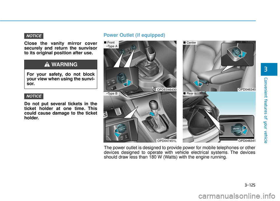
Power Outlet (if equipped)
NOTICE
NOTICE
For your safety, do not block
your view when using the sunvi-
sor.
WARNING
OPD046340
■Center
OPD046341
■Rear
OPD047451L
■Front
OPDE046430
A
B
The power outlet is designed to provide power for mobile telephones or other
devices designed to operate with vehicle electrical systems. The devices
should draw less than 180 W (Watts) with the engine running.
Page 211 of 478
3-126
Convenient features of your vehicle
To prevent damage to the Power
Outlets :
Use the power outlet only when the engine is running and
remove the accessory plug after
use. Using the accessory plug
for prolonged periods of time
with the engine off could cause
the battery to discharge.
Only use 12V electric acces- sories which are less than 180 W
(Watts) in electric capacity.
Adjust the air-conditioner or heater to the lowest operating
level when using the power outlet.
Close the cover when not in use. (Continued)(Continued)
Some electronic devices can
cause electronic interference
when plugged into a vehicle’s
power outlet. These devices may
cause excessive audio static
and malfunctions in other elec-
tronic systems or devices used
in your vehicle.
Push the plug in as far as it will go. If good contact is not made,
the plug may overheat and the
fuse may open.
Plug in battery equipped electri- cal/electronic devices with
reverse current protection. The
current from the battery may
flow into the vehicle’s electri-
cal/electronic system and cause
system malfunction.
Wireless Cellular Phone
Charging System (if equipped)
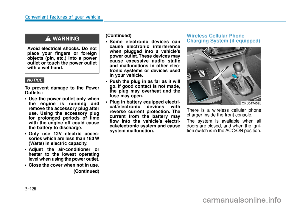
There is a wireless cellular phone
charger inside the front console.
The system is available when all
doors are closed, and when the igni-
tion switch is in the ACC/ON position.
NOTICE
Avoid electrical shocks. Do not
place your fingers or foreign
objects (pin, etc.) into a power
outlet or touch the power outlet
with a wet hand.
WARNING
OPD047452L
Page 212 of 478
3-127
Convenient features of your vehicle
3
To charge a cellular phone
The wireless cellular phone charging
system charges only the Qi-enabled
cellular phones ( ). Read the label
on the cellular phone accessory
cover or visit your cellular phone
manufacturer’s website to check
whether your cellular phone supports
the Qi technology.
The wireless charging process starts
when you put a Qi-enabled cellular
phone on the wireless charging unit.
1. Remove other items, including thesmart key, from the wireless charg-
ing unit. If not, the wireless charg-
ing process may be interrupted.
2. The indicator light is orange when the phone is charging. The indica-
tor light turns green when phone
charging is complete.
3. You can turn ON or OFF the wire- less charging function in the user
settings mode on the instrument
cluster. For further information,
refer to the "LCD Display Modes"
in this chapter. If your phone is not charging:
- Slightly change the position of the
cellular phone on the charging pad.
- Make sure the indicator light is orange.
Depending on the cellular phone
type, the indicator light may not turn
green even though the charging is
complete.
The indicator light will blink orange
for 10 seconds if there is a malfunc-
tion in the wireless charging system.
In this case, temporarily stop the
charging process, and re-attempt to
wirelessly charge your cellular phone
again.
The system warns you with a mes-
sage on the LCD display if the cellular
phone is still on the wireless charging
unit after the engine is turned OFF
and the front door is opened. The wireless cellular phone
charging system may not sup-
port certain cellular phones,
which are not verified for the Qi
specification ( ).
Locate your cell phone well in the middle of the wireless cellu-
lar phone charging system.
Even when your cell phone
locates slightly to one side, the
charging speed may decrease.
The wireless charging process may temporarily stop, when a
smart key function operates (i.e.
starting the vehicle, opening the
doors, closing the doors).
For certain cell phones, the indi- cator color may not change to
green, even when the wireless
charging process is properly
completed.
(Continued)
NOTICE
Page 220 of 478
Driving your vehicle
5
Before Driving ........................................................5-4
Before Entering the Vehicle ...........................................5-4
Before Starting ..................................................................5-4
Ignition Switch ........................................................5-6
Key Ignition Switch ...........................................................5-6
Engine Start/Stop Button................................................5-9
Manual Transmission ...........................................5-16
Manual Transmission Operation ..................................5-16
Good Driving Practices ..................................................5-18
Automatic Transmission ......................................5-19
Automatic Transmission Operation .............................5-19
Good Driving Practices ..................................................5-23
Dual Clutch Transmission ....................................5-25
Dual Clutch Transmission Operation ..........................5-25
Good Driving Practices ..................................................5-33
Braking System ....................................................5-35
Power Brakes ...................................................................5-35
Disc Brakes Wear Indicator ..........................................5-36
Parking Brake (Hand type) ...........................................5-36
Electronic Parking Brake (EPB)...................................5-38
Auto Hold ........................................................................\
..5-43
Anti-lock Brake System (ABS) ....................................5-47Electronic Stability Control (ESC)................................5-48
Vehicle Stability Management (VSM).........................5-51
Hill-Start Assist Control (HAC) ....................................5-53
Good Braking Practices .................................................5-53
Drive Mode Integrated Control System ............5-54
Blind Spot Detection System (BSD) ..................5-55
BSD (Blind Spot Detection) /
LCA (Lane Change Assist) .............................................5-56
RCTA (Rear Cross Traffic Alert) ..................................5-59
Limitations of the System .............................................5-61
Automatic Emergency Braking (AEB) ...............5-62
System Setting and Activation.....................................5-62
AEB Warning Message and System Control ............5-64
AEB Front Radar Sensor ...............................................5-66
System Malfunction .......................................................5-68
Limitations of the System .............................................5-69
Lane Keeping Assist System (LKAS) .................5-74
LKAS Operation ...............................................................5-75
Warning Light and Message.........................................5-79
Limitations of the System .............................................5-80
LKAS Function Change ..................................................5-81
Page 222 of 478
5-3
Driving your vehicle
5
Carbon monoxide (CO) gas is toxic. Breathing CO can cause unconsciousness and death.
Engine exhaust contains carbon monoxide which cannot be seen or smelled.
Do not inhale engine exhaust.
If at any time you smell engine exhaust inside the vehicle, open the windows immediately. Exposure to CO can cause
unconsciousness and death by asphyxiation.
Be sure the exhaust system does not leak.
The exhaust system should be checked whenever the vehicle is raised to change the oil or for any other purpose. If
you hear a change in the sound of the exhaust or if you drive over something that strikes the underneath side of the
vehicle, have the exhaust system checked as soon as possible by an authorized HYUNDAI dealer.
Do not run the engine in an enclosed area.
Letting the engine idle in your garage, even with the garage door open, is a hazardous practice. Run the engine only
long enough to start the engine and to move the vehicle out of the garage.
Avoid idling the engine for prolonged periods with people inside the vehicle.
If it is necessary to idle the engine for a prolonged period with people inside the vehicle, be sure to do so only in an
open area with the air intake set at "Fresh" and fan control set to high so fresh air is drawn into the interior.
Keep the air intakes clear.
To assure proper operation of the ventilation system, keep the ventilation air intakes located in front of the windshield
clear of snow, ice, leaves, or other obstructions.
If you must drive with the liftgate open:
Close all windows.
Open instrument panel air vents.
Set the air intake control at "Fresh", the air flow control at "Floor" or "Face", and the fan control set to high.
WARNING
Page 223 of 478
5-4
Driving your vehicle
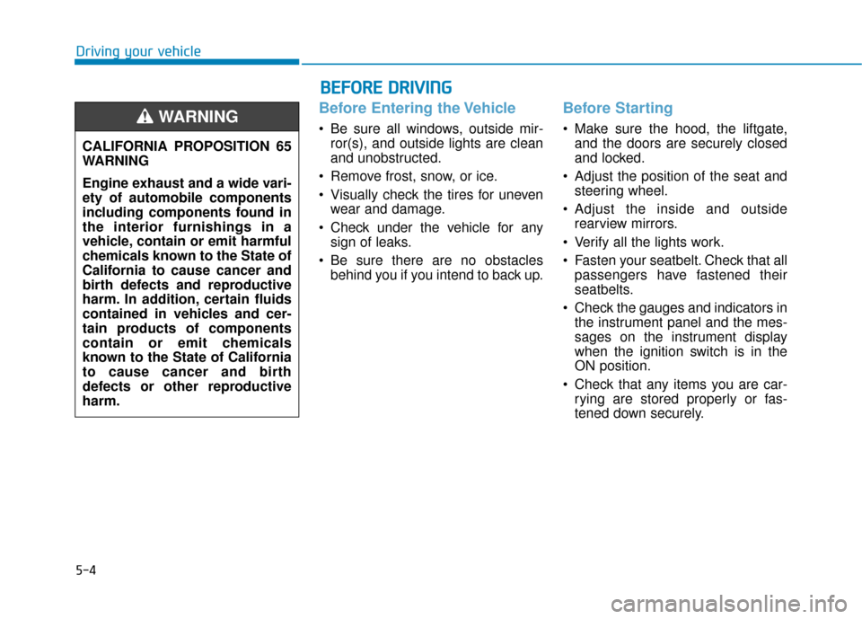
Before Entering the Vehicle
• Be sure all windows, outside mir-ror(s), and outside lights are clean
and unobstructed.
Remove frost, snow, or ice.
Visually check the tires for uneven wear and damage.
Check under the vehicle for any sign of leaks.
Be sure there are no obstacles behind you if you intend to back up.
Before Starting
Make sure the hood, the liftgate,and the doors are securely closed
and locked.
Adjust the position of the seat and steering wheel.
Adjust the inside and outside rearview mirrors.
Verify all the lights work.
Fasten your seatbelt. Check that all passengers have fastened their
seatbelts.
Check the gauges and indicators in the instrument panel and the mes-
sages on the instrument display
when the ignition switch is in the
ON position.
Check that any items you are car- rying are stored properly or fas-
tened down securely.
CALIFORNIA PROPOSITION 65
WARNING
Engine exhaust and a wide vari-
ety of automobile components
including components found in
the interior furnishings in a
vehicle, contain or emit harmful
chemicals known to the State of
California to cause cancer and
birth defects and reproductive
harm. In addition, certain fluids
contained in vehicles and cer-
tain products of components
contain or emit chemicals
known to the State of California
to cause cancer and birth
defects or other reproductive
harm.WARNING
B B
E
EF
FO
O R
RE
E
D
D R
RI
IV
V I
IN
N G
G
Page 225 of 478
5-6
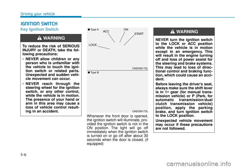
Key Ignition Switch
Whenever the front door is opened,
the ignition switch will illuminate, pro-
vided the ignition switch is not in the
ON position. The light will go off
immediately when the ignition switch
is turned on or go off after about 30
seconds when the door is closed. (if
equipped)
I IG
G N
N I
IT
T I
IO
O N
N
S
S W
W I
IT
T C
CH
H
Driving your vehicle
To reduce the risk of SERIOUS
INJURY or DEATH, take the fol-
lowing precautions:
NEVER allow children or any
person who is unfamiliar with
the vehicle to touch the igni-
tion switch or related parts.
Unexpected and sudden vehi-
cle movement can occur.
NEVER reach through the
steering wheel for the ignition
switch, or any other control,
while the vehicle is in motion.
The presence of your hand or
arm in this area may cause a
loss of vehicle control result-
ing in an accident.
WARNING NEVER turn the ignition switch
to the LOCK or ACC position
while the vehicle is in motion
except in an emergency. This
will result in the engine turning
off and loss of power assist for
the steering and brake systems.
This may lead to loss of direc-
tional control and braking func-
tion, which could cause an acci-
dent.
Before leaving the driver's seat,
always make sure the shift lever
is in 1
stgear (for manual trans-
mission vehicle) or P (Park, for
automatic transmission/dual
clutch transmission vehicle)
position, apply the parking
brake, and turn ignition switch
to the LOCK position.
Unexpected vehicle movement
may occur if these precautions
are not followed.
WARNING
OAE056172L
OAE056173L
LOCK ACC
ON
START
■Type A
■Type B