sensor HYUNDAI ELANTRA GT 2020 Owner's Guide
[x] Cancel search | Manufacturer: HYUNDAI, Model Year: 2020, Model line: ELANTRA GT, Model: HYUNDAI ELANTRA GT 2020Pages: 495, PDF Size: 15.22 MB
Page 314 of 495
5-91
Driving your vehicle
5
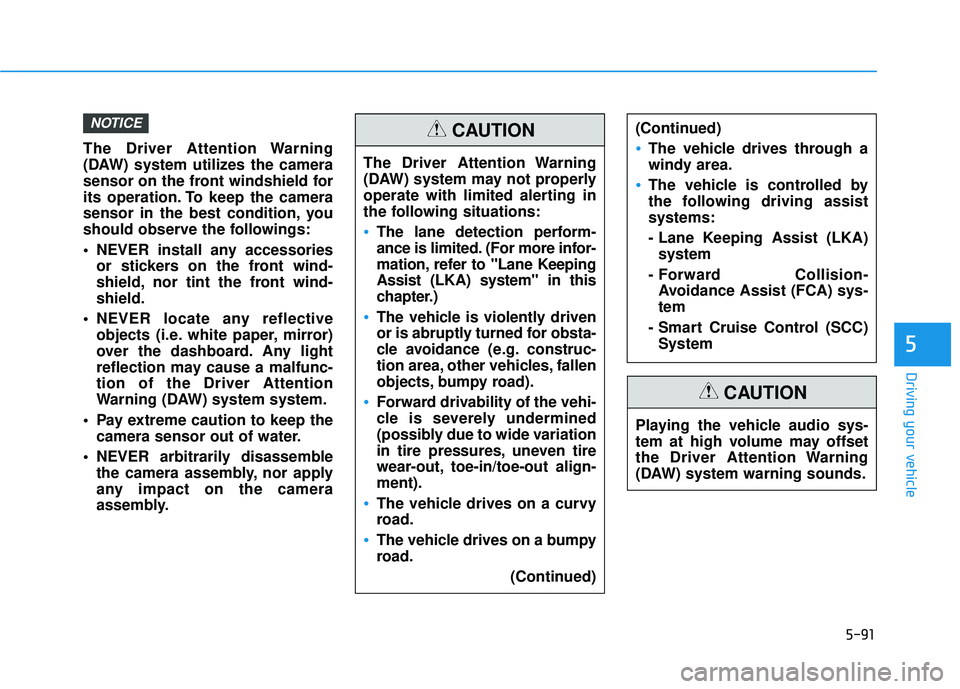
The Driver Attention Warning
(DAW) system utilizes the camera
sensor on the front windshield for
its operation. To keep the camera
sensor in the best condition, you
should observe the followings:
NEVER install any accessoriesor stickers on the front wind-
shield, nor tint the front wind-
shield.
NEVER locate any reflective objects (i.e. white paper, mirror)
over the dashboard. Any light
reflection may cause a malfunc-
tion of the Driver Attention
Warning (DAW) system system.
Pay extreme caution to keep the camera sensor out of water.
NEVER arbitrarily disassemble the camera assembly, nor apply
any impact on the camera
assembly.
NOTICE
The Driver Attention Warning
(DAW) system may not properly
operate with limited alerting in
the following situations:
The lane detection perform-
ance is limited. (For more infor-
mation, refer to "Lane Keeping
Assist (LKA) system" in this
chapter.)
The vehicle is violently driven
or is abruptly turned for obsta-
cle avoidance (e.g. construc-
tion area, other vehicles, fallen
objects, bumpy road).
Forward drivability of the vehi-
cle is severely undermined
(possibly due to wide variation
in tire pressures, uneven tire
wear-out, toe-in/toe-out align-
ment).
The vehicle drives on a curvy
road.
The vehicle drives on a bumpy
road.
(Continued)
(Continued)
The vehicle drives through a
windy area.
The vehicle is controlled by
the following driving assist
systems:
- Lane Keeping Assist (LKA)system
- Forward Collision- Avoidance Assist (FCA) sys-
tem
- Smart Cruise Control (SCC) System
CAUTION
Playing the vehicle audio sys-
tem at high volume may offset
the Driver Attention Warning
(DAW) system warning sounds.
CAUTION
Page 325 of 495
5-102
Driving your vehicle
Smart Cruise Control set speedwill be temporarily canceledwhen:
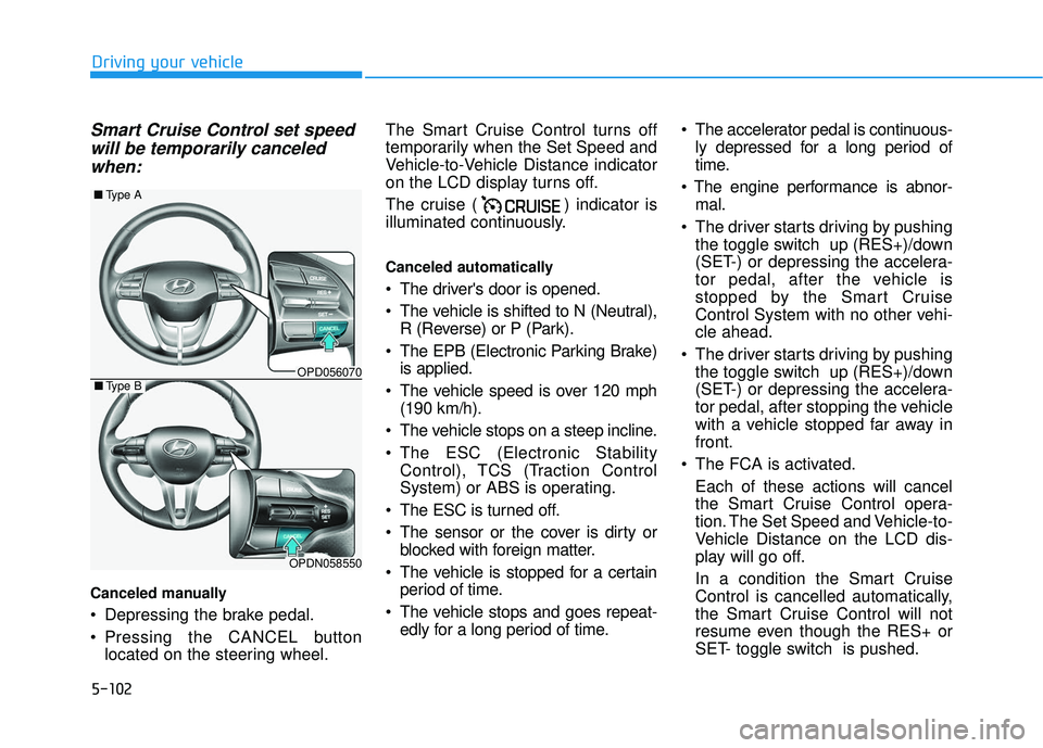
Canceled manually
Depressing the brake pedal.
Pressing the CANCEL button
located on the steering wheel. The Smart Cruise Control turns off
temporarily when the Set Speed and
Vehicle-to-Vehicle Distance indicator
on the LCD display turns off.
The cruise ( ) indicator is
illuminated continuously.
Canceled automatically
The driver's door is opened.
The vehicle is shifted to N (Neutral),
R (Reverse) or P (Park).
The EPB (Electronic Parking Brake) is applied.
The vehicle speed is over 120 mph (190 km/h).
The vehicle stops on a steep incline.
The ESC (Electronic Stability Control), TCS (Traction Control
System) or ABS is operating.
The ESC is turned off.
The sensor or the cover is dirty or blocked with foreign matter.
The vehicle is stopped for a certain period of time.
The vehicle stops and goes repeat- edly for a long period of time. The accelerator pedal is continuous-
ly depressed for a long period of
time.
mal.
The driver starts driving by pushing the toggle switch up (RES+)/down
(SET-) or depressing the accelera-
tor pedal, after the vehicle is
stopped by the Smart Cruise
Control System with no other vehi-
cle ahead.
The driver starts driving by pushing the toggle switch up (RES+)/down
(SET-) or depressing the accelera-
tor pedal, after stopping the vehicle
with a vehicle stopped far away in
front.
The FCA is activated. Each of these actions will cancel
the Smart Cruise Control opera-
tion. The Set Speed and Vehicle-to-
Vehicle Distance on the LCD dis-
play will go off.
In a condition the Smart Cruise
Control is cancelled automatically,
the Smart Cruise Control will not
resume even though the RES+ or
SET- toggle switch is pushed.
OPD056070
■ Type A
OPDN058550
■Type B
Page 330 of 495
5-107
Driving your vehicle
5
Sensor to Detect Distance to
the Vehicle Ahead
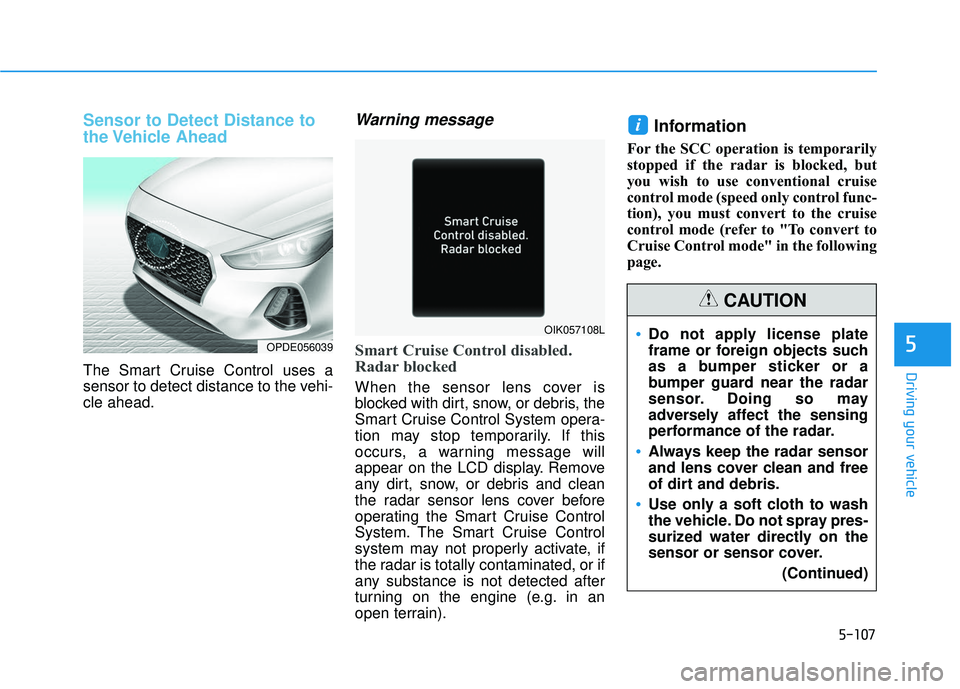
The Smart Cruise Control uses a
sensor to detect distance to the vehi-
cle ahead.
Warning message
Smart Cruise Control disabled.
Radar blocked
When the sensor lens cover is
blocked with dirt, snow, or debris, the
Smart Cruise Control System opera-
tion may stop temporarily. If this
occurs, a warning message will
appear on the LCD display. Remove
any dirt, snow, or debris and clean
the radar sensor lens cover before
operating the Smart Cruise Control
System. The Smart Cruise Control
system may not properly activate, if
the radar is totally contaminated, or if
any substance is not detected after
turning on the engine (e.g. in an
open terrain).
Information
For the SCC operation is temporarily
stopped if the radar is blocked, but
you wish to use conventional cruise
control mode (speed only control func-
tion), you must convert to the cruise
control mode (refer to "To convert to
Cruise Control mode" in the following
page.
i
OPDE056039
OIK057108LDo not apply license plate
frame or foreign objects such
as a bumper sticker or a
bumper guard near the radar
sensor. Doing so may
adversely affect the sensing
performance of the radar.
Always keep the radar sensor
and lens cover clean and free
of dirt and debris.
Use only a soft cloth to wash
the vehicle. Do not spray pres-
surized water directly on the
sensor or sensor cover.(Continued)
CAUTION
Page 331 of 495
5-108
Driving your vehicle
Check Smart Cruise Control System
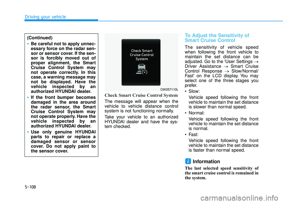
The message will appear when the
vehicle to vehicle distance control
system is not functioning normally.
Take your vehicle to an authorized
HYUNDAI dealer and have the sys-
tem checked.
To Adjust the Sensitivity of
Smart Cruise Control
The sensitivity of vehicle speed
when following the front vehicle to
maintain the set distance can be
adjusted. Go to the 'User Settings →
Driver Assistance →Smart Cruise
Control Response → Slow/Normal/
Fast' on the LCD display. You may
select one of the three stages you
prefer.
Slow:
Vehicle speed following the front
vehicle to maintain the set distance
is slower than normal speed.
Normal: Vehicle speed following the front
vehicle to maintain the set distance
is normal.
Fast: Vehicle speed following the front
vehicle to maintain the set distance
is faster than normal speed.
Information
The last selected speed sensitivity of
the smart cruise control is remained in
the system.
i
(Continued)
Be careful not to apply unnec-
essary force on the radar sen-
sor or sensor cover. If the sen-
sor is forcibly moved out of
proper alignment, the Smart
Cruise Control System may
not operate correctly. In this
case, a warning message may
not be displayed. Have the
vehicle inspected by an
authorized HYUNDAI dealer.
If the front bumper becomes
damaged in the area around
the radar sensor, the Smart
Cruise Control System may
not operate properly. Have the
vehicle inspected by an
authorized HYUNDAI dealer.
Use only genuine HYUNDAI
parts to repair or replace a
damaged sensor or sensor
cover. Do not apply paint to
the sensor cover.
OIK057110L
Page 334 of 495
5-111
Driving your vehicle
5
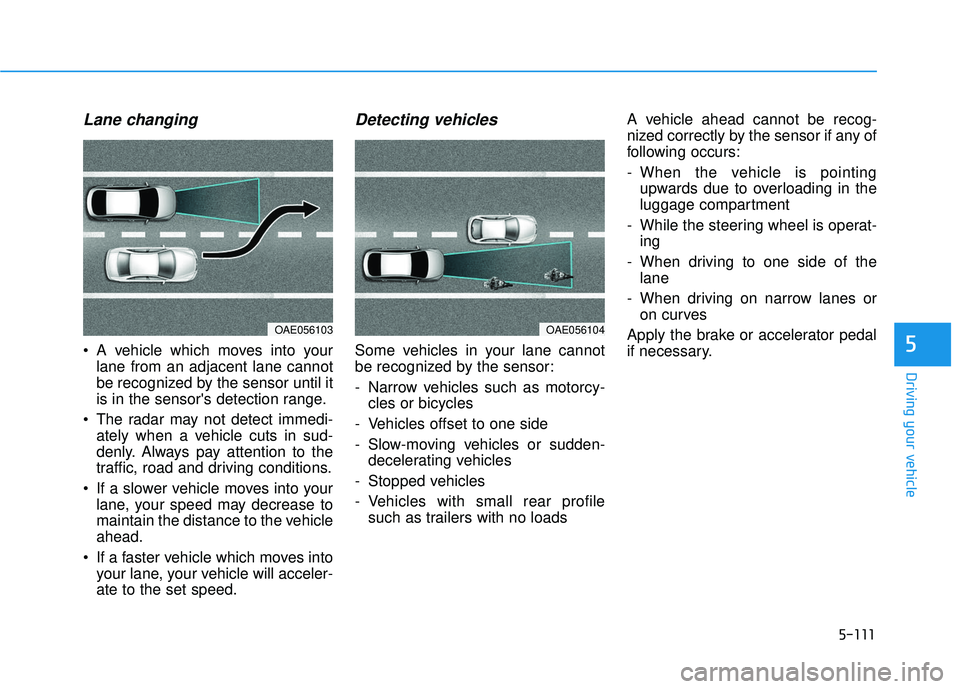
Lane changing
A vehicle which moves into yourlane from an adjacent lane cannot
be recognized by the sensor until it
is in the sensor's detection range.
The radar may not detect immedi- ately when a vehicle cuts in sud-
denly. Always pay attention to the
traffic, road and driving conditions.
If a slower vehicle moves into your lane, your speed may decrease to
maintain the distance to the vehicle
ahead.
If a faster vehicle which moves into your lane, your vehicle will acceler-
ate to the set speed.
Detecting vehicles
Some vehicles in your lane cannot
be recognized by the sensor:
- Narrow vehicles such as motorcy-cles or bicycles
- Vehicles offset to one side
- Slow-moving vehicles or sudden- decelerating vehicles
- Stopped vehicles
- Vehicles with small rear profile such as trailers with no loads A vehicle ahead cannot be recog-
nized correctly by the sensor if any of
following occurs:
- When the vehicle is pointing
upwards due to overloading in the
luggage compartment
- While the steering wheel is operat- ing
- When driving to one side of the lane
- When driving on narrow lanes or on curves
Apply the brake or accelerator pedal
if necessary.
OAE056103OAE056104
Page 361 of 495
6-10
What to do in an emergency
If any of the below happens, have
the system checked by an author-
ized HYUNDAI dealer.
1. The Low Tire Pressure TPMS Malfunction Indicator does not
illuminate for 3 seconds when
the ignition switch is placed to
the ON position or engine is
running.
2. The TPMS Malfunction Indicator remains illuminated after blink-
ing for approximately 1 minute.
3. The Low Tire Pressure LCD dis- play remains illuminated
Low Tire Pressure
Telltale
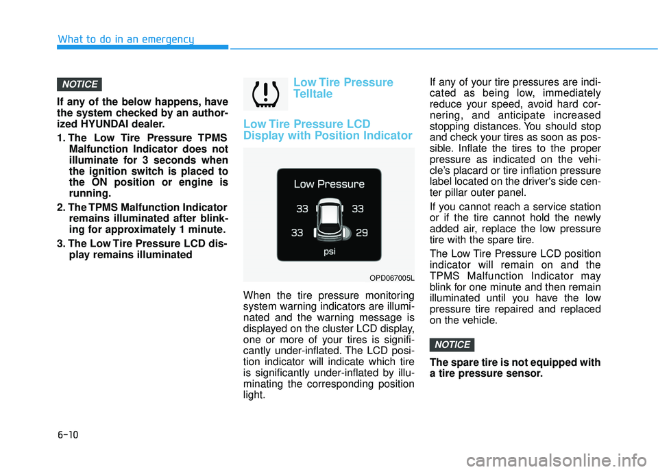
Low Tire Pressure LCD
Display with Position Indicator
When the tire pressure monitoring
system warning indicators are illumi-
nated and the warning message is
displayed on the cluster LCD display,
one or more of your tires is signifi-
cantly under-inflated. The LCD posi-
tion indicator will indicate which tire
is significantly under-inflated by illu-
minating the corresponding position
light. If any of your tire pressures are indi-
cated as being low, immediately
reduce your speed, avoid hard cor-
nering, and anticipate increased
stopping distances. You should stop
and check your tires as soon as pos-
sible. Inflate the tires to the proper
pressure as indicated on the vehi-
cle’s placard or tire inflation pressure
label located on the driver's side cen-
ter pillar outer panel.
If you cannot reach a service station
or if the tire cannot hold the newly
added air, replace the low pressure
tire with the spare tire.
The Low Tire Pressure LCD position
indicator will remain on and the
TPMS Malfunction Indicator may
blink for one minute and then remain
illuminated until you have the low
pressure tire repaired and replaced
on the vehicle.
The spare tire is not equipped with
a tire pressure sensor.
NOTICE
NOTICE
OPD067005L
Page 363 of 495
6-12
What to do in an emergency
The TPMS Malfunction Indicator
may illuminate after blinking for
one minute if the vehicle is near
electric power supply cables or
radio transmitters such as police
stations, government and public
offices, broadcasting stations,
military installations, airports,
transmitting towers, etc.
Additionally, the TPMS Malfunction
Indicator may illuminate if snow
chains are used or electronic
devices such as computers, charg-
ers, remote starters, navigation,
etc. This may interfere with normal
operation of the TPMS.
Changing a Tire with TPMS
If you have a flat tire, the Low Tire
Pressure and LCD position indicator
will come on. Have the flat tire
repaired by an authorized HYUNDAI
dealer as soon as possible or
replace the flat tire with the spare
tire.
The spare tire does not come with a
tire pressure monitoring sensor.
When the low pressure tire or the flat
tire is replaced with the spare tire,
the Low Tire Pressure LCD position
indicator will remain on. Also, the
TPMS Malfunction Indicator will illu-
minate after blinking for one minute if
the vehicle is driven at speed above
15.5 mph (25 km/h) for approximate-
ly 20 minutes. Once the original tire equipped with
a tire pressure monitoring sensor is
reinflated to the recommended pres-
sure and reinstalled on the vehicle,
the Low Tire Pressure LCD position
indicator and TPMS Malfunction
Indicator will go off within a few min-
utes of driving.
If the indicators do not disappear
after a few minutes, please visit an
authorized HYUNDAI dealer.
Each wheel is equipped with a tire
pressure sensor mounted inside the
tire behind the valve stem (except for
the spare tire). You must use TPMS
specific wheels. It is recommended
that you always have your tires serv-
iced by an authorized HYUNDAI
dealer.
NOTICE
Never use a puncture-repairing
agent not approved by HYUNDAI
dealer to repair and/or inflate a
low pressure tire. Tire sealant
not approved by HYUNDAI deal-
er may damage the tire pressure
sensor.
CAUTION
Page 372 of 495
6-21
What to do in an emergency
6
When towing your vehicle in an
emergency without wheel dollies:
1.Place the ignition switch in theACC position.
2.Place the shift lever in N (Neutral).
3.Release the parking brake.
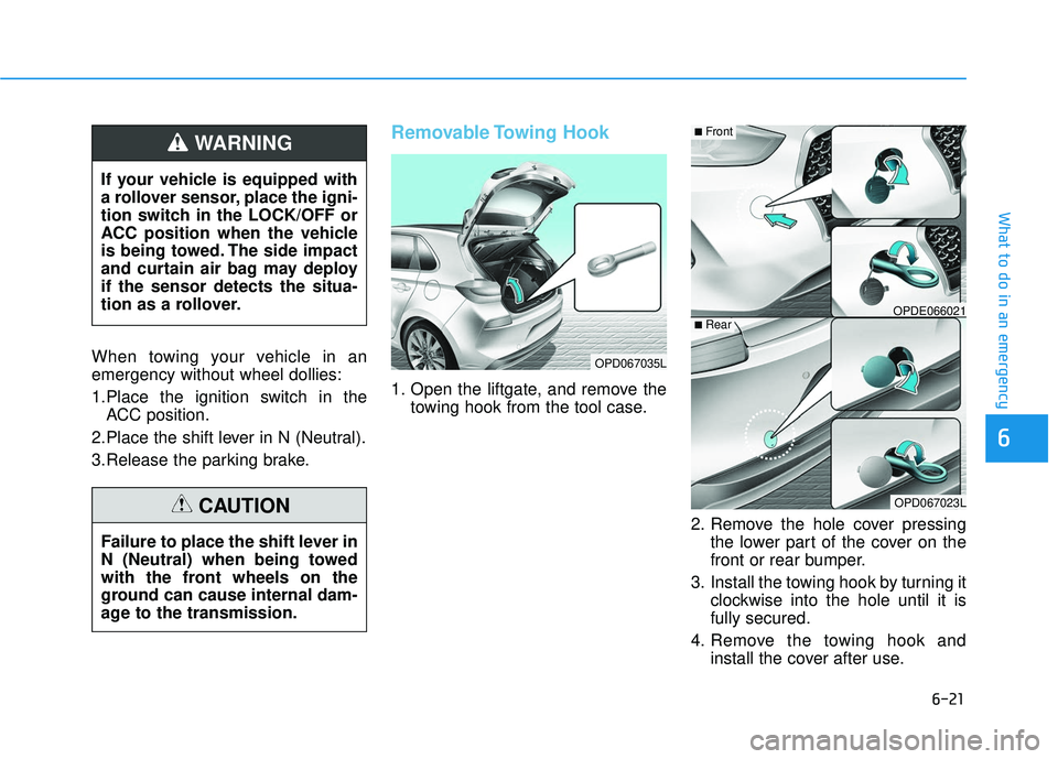
Removable Towing Hook
1. Open the liftgate, and remove the towing hook from the tool case.
2. Remove the hole cover pressingthe lower part of the cover on the
front or rear bumper.
3. Install the towing hook by turning it clockwise into the hole until it is
fully secured.
4. Remove the towing hook and install the cover after use.
If your vehicle is equipped with
a rollover sensor, place the igni-
tion switch in the LOCK/OFF or
ACC position when the vehicle
is being towed. The side impact
and curtain air bag may deploy
if the sensor detects the situa-
tion as a rollover.
WARNING
Failure to place the shift lever in
N (Neutral) when being towed
with the front wheels on the
ground can cause internal dam-
age to the transmission.
CAUTION
OPD067035L
OPDE066021
OPD067023L
■Front
■Rear
Page 404 of 495
7-30
Maintenance
Information
If the vehicle is operated in extremely
dusty or sandy areas, replace the ele-
ment more often than the usual rec-
ommended intervals (refer to
"Maintenance Under Severe Usage
Conditions" in this chapter).
Do not drive with the air cleanerfilter removed. This will result in
excessive engine wear.
When removing the air cleaner filter, be careful that dust or dirt
does not enter the air intake, or
damage may result.
Use HYUNDAI genuine parts. Use of non-genuine parts could
damage the air flow sensor.
Filter Inspection
The climate control air filter should
be replaced according to the
Maintenance Schedule. If the vehicle
is operated in severely air-polluted
cities or on dusty rough roads for a
long period, it should be inspected
more frequently and replaced earlier.
When you replace the climate control
air filter, replace it performing the fol-
lowing procedure, and be careful to
avoid damaging other components.
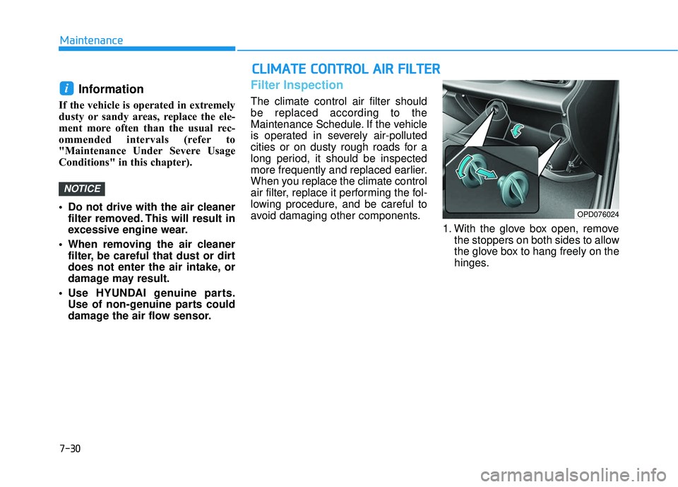
1. With the glove box open, removethe stoppers on both sides to allow
the glove box to hang freely on the
hinges.
NOTICE
i
C CL
LI
IM
M A
AT
TE
E
C
C O
O N
NT
TR
R O
O L
L
A
A I
IR
R
F
F I
IL
L T
T E
ER
R
OPD076024
Page 435 of 495
7-61
7
Maintenance
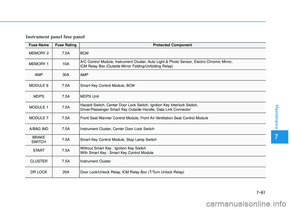
Fuse NameFuse RatingProtected Component
MEMORY 27.5ABCM
MEMORY 110AA/C Control Module, Instrument Cluster, Auto Light & Photo Sensor, Electro Chromic Mirror,
ICM Relay Box (Outside Mirror Folding/Unfolding Relay)
AMP30AAMP
MODULE 6 7.5ASmart Key Control Module, BCM
MDPS7.5AMDPS Unit
MODULE 17.5AHazard Switch, Center Door Lock Switch, Ignition Key Interlock Switch,
Driver/Passenger Smart Key Outside Handle, Data Link Connector
MODULE 77.5AFront Seat Warmer Control Module, Front Air Ventilation Seat Control Module
A/BAG IND7.5AInstrument Cluster, Center Door Lock Switch
BRAKE
SWITCH7.5ASmart Key Control Module, Stop Lamp Switch
START7.5AWithout Smart Key : Ignition Key Switch
With Smart Key : Smart Key Control Module
CLUSTER7.5AInstrument Cluster
DR LOCK20ADoor Lock/Unlock Relay, ICM Relay Box (T/Turn Unlock Relay)
Instrument panel fuse panel