stop start HYUNDAI ELANTRA SE 2017 Service Manual
[x] Cancel search | Manufacturer: HYUNDAI, Model Year: 2017, Model line: ELANTRA SE, Model: HYUNDAI ELANTRA SE 2017Pages: 586, PDF Size: 15.29 MB
Page 427 of 586
6-2
The hazard warning flasher serves
as a warning to other drivers to exer-
cise extreme caution when approach-
ing, overtaking, or passing your vehi-
cle.
It should be used whenever emer-
gency repairs are being made or
when the vehicle is stopped near the
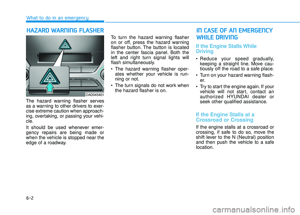
edge of a roadway.To turn the hazard warning flasher
on or off, press the hazard warning
flasher button. The button is located
in the center fascia panel. Both the
left and right turn signal lights will
flash simultaneously.
• The hazard warning flasher oper-
ates whether your vehicle is run-
ning or not.
The turn signals do not work when the hazard flasher is on.
If the Engine Stalls While
Driving
Reduce your speed gradually,keeping a straight line. Move cau-
tiously off the road to a safe place.
Turn on your hazard warning flash- er.
Try to start the engine again. If your vehicle will not start, contact an
authorized HYUNDAI dealer or
seek other qualified assistance.
If the Engine Stalls at a
Crossroad or Crossing
If the engine stalls at a crossroad or
crossing, if safe to do so, move the
shift lever to the N (Neutral) position
and then push the vehicle to a safe
location.
H HA
AZ
ZA
A R
RD
D
W
W A
AR
RN
N I
IN
N G
G
F
F L
LA
A S
SH
H E
ER
R
What to do in an emergency
I
IN
N
C
C A
A S
SE
E
O
O F
F
A
A N
N
E
E M
M E
ER
R G
G E
EN
N C
CY
Y
W
W H
HI
IL
L E
E
D
D R
RI
IV
V I
IN
N G
G
OAD045401
Page 428 of 586
6-3
What to do in an emergency
If you Have a Flat Tire While
Driving
If a tire goes flat while you are driving:
Take your foot off the acceleratorpedal and let the vehicle slow down
while driving straight ahead. Do not
apply the brakes immediately or
attempt to pull off the road as this
may cause loss of vehicle control
resulting in an accident. When the
vehicle has slowed to such a speed
that it is safe to do so, brake care-
fully and pull off the road. Drive off
the road as far as possible and park
on firm, level ground. If you are on
a divided highway, do not park in
the median area between the two
traffic lanes.
When the vehicle is stopped, press the hazard warning flasher button,
move the shift lever into P(Park),
and apply the parking brake, and
place the ignition switch in the
LOCK/OFF position.
Have all passengers get out of the vehicle. Be sure they all get out on
the side of the vehicle that is away
from traffic.
When changing a flat tire, follow the instructions provided later in
this chapter.
If the Engine Doesn't Turn
Over or Turns Over Slowly
Be sure the shift lever is in N
(Neutral) or P (Park). The engine
starts only when the shift lever is in
N (Neutral) or P (Park).
Check the battery connections to be sure they are clean and tight.
Turn on the interior light. If the light dims or goes out when you operate
the starter, the battery is drained.
Do not push or pull the vehicle to
start it. This could cause damage to
your vehicle. See instructions for
"Jump Starting" provided in this
chapter.
If the Engine Turns Over
Normally but Doesn't Start
Check the fuel level and add fuel if
necessary.
If the engine still does not start, have
your vehicle checked by an author-
ized HYUNDAI dealer.
6
I I F
F
T
T H
H E
E
E
E N
N G
GI
IN
N E
E
W
W I
IL
L L
L
N
N O
O T
T
S
S T
T A
A R
RT
T
Push or pull starting the vehicle
may cause the catalytic con-
verter to overload which can
lead to damage to the emission
control system.
CAUTION
Page 434 of 586
6-9
What to do in an emergency
6
T
TI
IR
R E
E
P
P R
R E
ES
SS
SU
U R
RE
E
M
M O
ON
NI
IT
T O
O R
RI
IN
N G
G
S
S Y
Y S
ST
T E
EM
M
(
( T
T P
P M
M S
S)
)
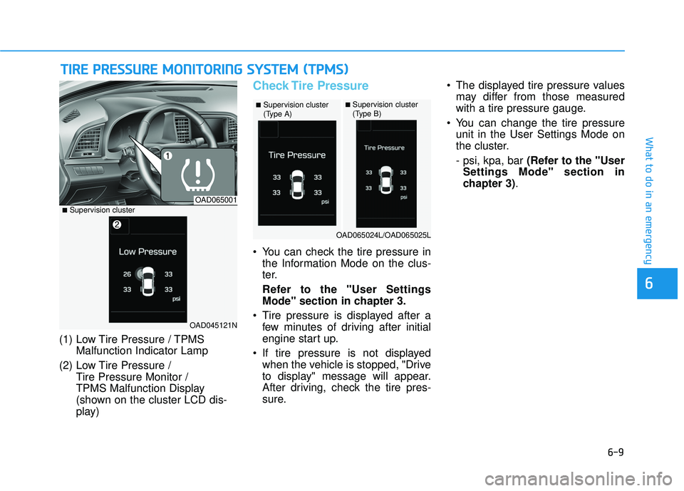
(1) Low Tire Pressure / TPMS
Malfunction Indicator Lamp
(2) Low Tire Pressure / Tire Pressure Monitor /
TPMS Malfunction Display
(shown on the cluster LCD dis-
play)
Check Tire Pressure
You can check the tire pressure inthe Information Mode on the clus-
ter.
Refer to the "User Settings
Mode" section in chapter 3.
Tire pressure is displayed after a few minutes of driving after initial
engine start up.
If tire pressure is not displayed when the vehicle is stopped, "Drive
to display" message will appear.
After driving, check the tire pres-
sure. The displayed tire pressure values
may differ from those measured
with a tire pressure gauge.
You can change the tire pressure unit in the User Settings Mode on
the cluster.
- psi, kpa, bar (Refer to the "User
Settings Mode" section in
chapter 3).
OAD065001
■Supervision cluster
(Type A)■Supervision cluster
(Type B)
OAD065024L/OAD065025L
■Supervision cluster
OAD045121N
Page 435 of 586
6-10
What to do in an emergency
Tire Pressure Monitoring
System
Each tire, including the spare (if pro-
vided), should be checked monthly
when cold and inflated to the inflation
pressure recommended by the vehi-
cle manufacturer on the vehicle plac-
ard or tire inflation pressure label. (If
your vehicle has tires of a different
size than the size indicated on the
vehicle placard or tire inflation pres-
sure label, you should determine the
proper tire inflation pressure for
those tires.)As an added safety feature, your
vehicle has been equipped with a tire
pressure monitoring system (TPMS)
that illuminates a low tire pressure
telltale when one or more of your
tires is significantly under-inflated.
Accordingly, when the low tire pres-
sure telltale illuminates, you should
stop and check your tires as soon as
possible, and inflate them to the
proper pressure. Driving on a signifi-
cantly under-inflated tire causes the
tire to overheat and can lead to tire
failure.
Under-inflation also reduces fuel effi-
ciency and tire tread life, and may
affect the vehicle’s handling and
stopping ability.
Please note that the TPMS is not a
substitute for proper tire mainte-
nance, and it is the driver’s responsi-
bility to maintain correct tire pres-
sure, even if under-inflation has not
reached the level to trigger illumina-
tion of the TPMS low tire pressure
telltale.Your vehicle has also been equipped
with a TPMS malfunction indicator to
indicate when the system is not
operating properly. The TPMS mal-
function indicator is combined with
the low tire pressure telltale. When
the system detects a malfunction,
the telltale will flash for approximate-
ly one minute and then remain con-
tinuously illuminated. This sequence
will continue upon subsequent vehi-
cle start-ups as long as the malfunc-
tion exists.
When the malfunction indicator is
illuminated, the system may not be
able to detect or signal low tire pres-
sure as intended. TPMS malfunc-
tions may occur for a variety of rea-
sons, including the installation of
replacement or alternate tires or
wheels on the vehicle that prevent
the TPMS from functioning properly.
Always check the TPMS malfunction
telltale after replacing one or more
tires or wheels on your vehicle to
ensure that the replacement or alter-
nate tires and wheels allow the
TPMS to continue to function proper-
ly.
Over-inflation or under-inflation
can reduce tire life, adversely
affect vehicle handling, and
lead to sudden tire failure that
may cause loss of vehicle con-
trol resulting in an accident.
WARNING
Page 487 of 586
7-27
7
Maintenance
Parking Brake
Inspect the parking brake system
including the parking brake pedal
and cables.
Brake Discs, Pads, Calipers
and Rotors
Check the pads for excessive wear,
discs for run out and wear, and
calipers for fluid leakage.
Exhaust Pipe and Muffler
Visually inspect the exhaust pipes,
muffler and hangers for cracks, dete-
rioration, or damage. Start the
engine and listen carefully for any
exhaust gas leakage. Tighten con-
nections or replace parts as neces-
sary.
Suspension Mounting Bolts
Check the suspension connections
for looseness or damage. Retighten
to the specified torque.
Steering Gear Box, Linkage &
Boots/Lower Arm Ball Joint
With the vehicle stopped and the
engine off, check for excessive free-
play in the steering wheel. Check the
linkage for bends or damage. Check
the dust boots and ball joints for
deterioration, cracks, or damage.
Replace any damaged parts.
Drive Shafts and Boots
Check the drive shafts, boots and
clamps for cracks, deterioration, or
damage. Replace any damaged
parts and, if necessary, repack the
grease.
Air Conditioning Refrigerant
Check the air conditioning lines and
connections for leakage and dam-
age.
Page 501 of 586
7-41
7
Maintenance
B
BA
A T
TT
TE
ER
R Y
Y
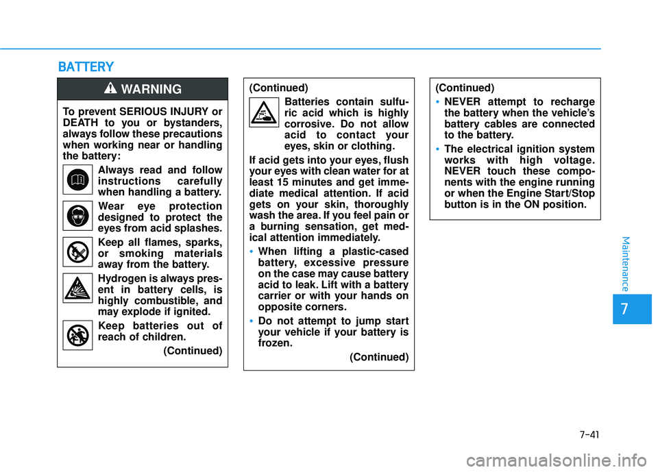
To prevent SERIOUS INJURY or
DEATH to you or bystanders,
always follow these precautions
when working near or handling
the battery:
Always read and follow
instructions carefully
when handling a battery.Wear eye protection
designed to protect the
eyes from acid splashes.
Keep all flames, sparks,
or smoking materials
away from the battery.
Hydrogen is always pres- ent in battery cells, is
highly combustible, and
may explode if ignited.
Keep batteries out of
reach of children.
(Continued)
WARNING (Continued)Batteries contain sulfu-
ric acid which is highly
corrosive. Do not allow
acid to contact your
eyes, skin or clothing.
If acid gets into your eyes, flush
your eyes with clean water for at
least 15 minutes and get imme-
diate medical attention. If acid
gets on your skin, thoroughly
wash the area. If you feel pain or
a burning sensation, get med-
ical attention immediately.
When lifting a plastic-cased
battery, excessive pressure
on the case may cause battery
acid to leak. Lift with a battery
carrier or with your hands on
opposite corners.
Do not attempt to jump start
your vehicle if your battery is
frozen. (Continued)
(Continued)
NEVER attempt to recharge
the battery when the vehicle’s
battery cables are connected
to the battery.
The electrical ignition system
works with high voltage.
NEVER touch these compo-
nents with the engine running
or when the Engine Start/Stop
button is in the ON position.
Page 503 of 586
7-43
7
Maintenance
By jump starting
After a jump start from a good bat-
tery, drive the vehicle for 20-30 min-
utes before it is shutoff. The vehicle
may not restart if you shut it off
before the battery had a chance to
adequately recharge. See "Jump
Starting" in chapter 6 for more infor-
mation on jump starting procedures.
Information
An inappropriately disposedbattery can be harmful to
the environment and human
health.
Dispose the battery according to your
local law(s) or regulation.
Reset features
Some items need to be reset after
the battery has been discharged or
the battery has been disconnected.
See chapter 3 for:
Power Windows
Trip Computer
Climate Control System
Clock
Audio System
Sunroof
i
(Continued)
Watch the battery during
charging, and stop or reduce
the charging rate if the battery
cells begin boiling violently.
The negative battery cable
must be removed first and
installed last when the battery
is disconnected. Disconnect
the battery charger in the fol-
lowing order:
(1) Turn off the battery charg- er main switch.
(2) Unhook the negative
clamp from the negative
battery terminal.
(3) Unhook the positive clamp from the positive battery
terminal.
Always use a genuine
HYUNDAI approved battery
when you replace the battery.
Page 528 of 586
7-68
Maintenance
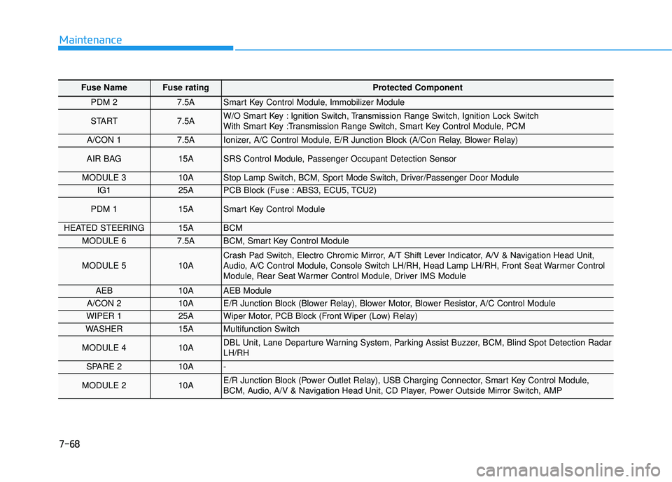
Fuse Name Fuse rating Protected Component
PDM 2 7.5A Smart Key Control Module, Immobilizer Module
START 7.5A W/O Smart Key : Ignition Switch, Transmission Range Switch, Ignition Lock Switch
With Smart Key :Transmission Range Switch, Smart Key Control Module, PCM
A/CON 1 7.5A Ionizer, A/C Control Module, E/R Junction Block (A/Con Relay, Blower Relay)
AIR BAG 15A SRS Control Module, Passenger Occupant Detection Sensor
MODULE 3 10A Stop Lamp Switch, BCM, Sport Mode Switch, Driver/Passenger Door Module
IG1 25A PCB Block (Fuse : ABS3, ECU5, TCU2)
PDM 1 15A Smart Key Control Module
HEATED STEERING 15A BCM
MODULE 6 7.5A BCM, Smart Key Control Module
MODULE 5 10A Crash Pad Switch, Electro Chromic Mirror, A/T Shift Lever Indicator, A/V & Navigation Head Unit,
Audio, A/C Control Module, Console Switch LH/RH, Head Lamp LH/RH, Front Seat Warmer Control
Module, Rear Seat Warmer Control Module, Driver IMS Module
AEB 10A AEB Module
A/CON 2 10A E/R Junction Block (Blower Relay), Blower Motor, Blower Resistor, A/C Control Module
WIPER 1 25A Wiper Motor, PCB Block (Front Wiper (Low) Relay)
WASHER 15A Multifunction Switch
MODULE 4 10A DBL Unit, Lane Departure Warning System, Parking Assist Buzzer, BCM, Blind Spot Detection Radar
LH/RH
SPARE 2 10A -
MODULE 2 10A E/R Junction Block (Power Outlet Relay), USB Charging Connector, Smart Key Control Module,
BCM, Audio, A/V & Navigation Head Unit, CD Player, Power Outside Mirror Switch, AMP
Page 558 of 586
7-98
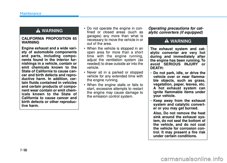
Maintenance Do not operate the engine in con-fined or closed areas (such as
garages) any more than what is
necessary to move the vehicle in or
out of the area.
When the vehicle is stopped in an open area for more than a short
time with the engine running,
adjust the ventilation system (as
needed) to draw outside air into the
vehicle.
Never sit in a parked or stopped vehicle for any extended time with
the engine running.
When the engine stalls or fails to start, excessive attempts to restart
the engine may cause damage to
the emission control system.
Operating precautions for cat-alytic converters (if equipped)
The exhaust system and cat-
alytic converter are very hot
during and immediately after
the engine has been running. To
avoid SERIOUS INJURY or
DEATH:
Do not park, idle, or drive the
vehicle over or near flamma-
ble objects, such as grass,
vegetation, paper, leaves, etc.
A hot exhaust system can
ignite flammable items under
your vehicle.
Keep away from the exhaust
system and catalytic convert-
er or you may get burned.
Also, Do not remove the heat
sink around the exhaust sys-
tem, do not seal the bottom of
the vehicle, and do not coat
the vehicle for corrosion con-
trol. It may present a fire risk
under certain conditions.
WARNING CALIFORNIA PROPOSITION 65
WARNING
Engine exhaust and a wide vari-
ety of automobile components
and parts, including compo-
nents found in the interior fur-
nishings in a vehicle, contain or
emit chemicals known to the
State of California to cause can-
cer and birth defects and repro-
ductive harm. In addition, cer-
tain fluids contained in vehicles
and certain products of compo-
nent wear contain or emit chem-
icals known to the State of
California to cause cancer and
birth defects or other reproduc-
tive harm.
WARNING
Page 577 of 586
I-4
Bulb replacementFront parking lamp .....................................................7-73
Front turn signal lamp ................................................7-73
Headlamp....................................................................7-73\
High mounted stop lamp ............................................7-86
Interior light bulb .......................................................7-88
License plate light bulb ..............................................7-87
Rear combination light bulb .......................................7-82
Side marker lamp .......................................................7-73
Side repeater lamp ......................................................7-82
Bulb wattage .....................................................................8-3\
Button start/stop, see engine start/stop button ..................5-9
Capacities (Lubricants) .....................................................3-6
Care Exterior care ...............................................................7-89
Interior care ................................................................7-95
Tire care ......................................................................7-\
44
Cartridge type fuse..........................................................7-65
Center console storage ..................................................3-150
Central door lock switch .................................................3-16
Certification label ...........................................................8-10
Chains Tire chains ..................................................................5-96
Changing a Tire with TPMS ...........................................6-14
Checking tire inflation pressure ......................................7-46 Child restraint system (CRS) ..........................................2-35
Booster seats...............................................................2-38
Children always in the rear ........................................2-35
Forward-facing child restraint system........................2-38
Installing a child restraint system (CRS) ...................2-38
Lower anchors and tether for children (LATCH system) .....................................................2-38
Rearward-facing child restraint system......................2-37
Securing a child restraint seat with "Tether Anchor" system......................................................................2-\
42
Securing a child restraint system with the LATCH anchors system ........................................................2-41
Securing a child restraint with a lap/shoulder belt.....2-43
Selecting a child restraint system (CRS) ...................2-36
Child-protector rear door locks.......................................3-19
Climate control air filter .................................................7-37
Clock ........................................................................\
.....3-156
Clothes hanger ..............................................................3-157
Combined instrument, see instrument cluster ................3-61
Compact spare tire replacement .....................................7-49
Coolant ........................................................................\
....7-30
Cooling fluid, see engine coolant ...................................7-30
Crankcase emission control system ................................7-96
Cruise control system .....................................................5-70
Cup holder.....................................................................3-1\
53
Curtain air bags ...............................................................2-50
Index
C