lights HYUNDAI ELANTRA SEL 2021 Workshop Manual
[x] Cancel search | Manufacturer: HYUNDAI, Model Year: 2021, Model line: ELANTRA SEL, Model: HYUNDAI ELANTRA SEL 2021Pages: 570, PDF Size: 52.21 MB
Page 338 of 570
07
7-25
• The pedestrian or cyclist is not
fully detected, for example, if the
pedestrian is leaning over or is not
fully walking upright
• The pedestrian or cyclist is wearing
clothing or equipment that makes it
difficult to detect as a pedestrian or
cyclist
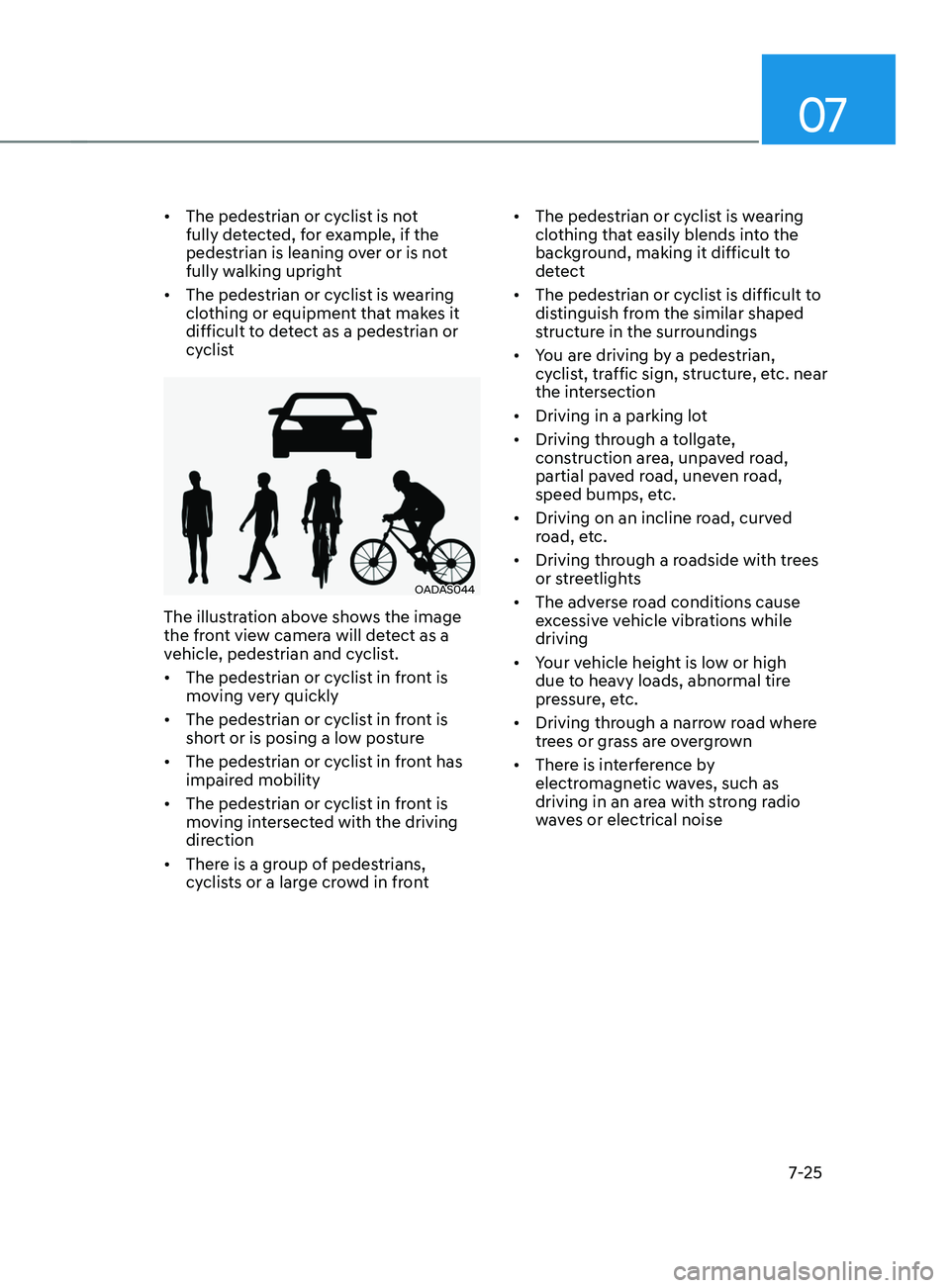
OADAS044
The illustration above shows the image
the front view camera will detect as a
vehicle, pedestrian and cyclist.
• The pedestrian or cyclist in front is
moving very quickly
• The pedestrian or cyclist in front is
short or is posing a low posture
• The pedestrian or cyclist in front has
impaired mobility
• The pedestrian or cyclist in front is
moving intersected with the driving
direction
• There is a group of pedestrians,
cyclists or a large crowd in front •
The pedestrian or cyclist is wearing
clothing that easily blends into the
background, making it difficult to
detect
• The pedestrian or cyclist is difficult to
distinguish from the similar shaped
structure in the surroundings
• You are driving by a pedestrian,
cyclist, traffic sign, structure, etc. near
the intersection
• Driving in a parking lot
• Driving through a tollgate,
construction area, unpaved road,
partial paved road, uneven road,
speed bumps, etc.
• Driving on an incline road, curved
road, etc.
• Driving through a roadside with trees
or streetlights
• The adverse road conditions cause
excessive vehicle vibrations while
driving
• Your vehicle height is low or high
due to heavy loads, abnormal tire
pressure, etc.
• Driving through a narrow road where
trees or grass are overgrown
• There is interference by
electromagnetic waves, such as
driving in an area with strong radio
waves or electrical noise
Page 383 of 570
Driver assistance system
7-7 0
Limitations of the function
Intelligent Speed Limit Assist may
not operate normally, or the system
may operate unexpectedly under the
following circumstances:
• The road sign is contaminated or
indistinguishable
- The road sign is difficult t
o see due
to bad weather, such as rain, snow,
fog, etc.
- The road sign is no
t clear or
damaged
- The road sign is partially obscur
ed
by surrounding objects or shadow
• The road signs do not conform to the
standard
- The te
xt or picture on the road sign
is different from the standard -
The road sign is installed between
the main line and the exit road or
between diverging roads
- An conditional road sign is no
t
installed with a sign located on the
road to enter or exit
- A sign is attached t
o another vehicle
• The brightness changes suddenly, for
example when entering or exiting a
tunnel or passing under a bridge
• Headlamps are not used or the
brightness of the headlamps are weak
at night or in the tunnel
• Road signs are difficult to recognize
due to the reflection of sunlight, street
lights, or oncoming vehicles
• The field of view of the front view
camera is obstructed by sun glare
• Driving on a road that is sharply
curved or continuously curved
• Driving through speed bumps, or
driving up and down or left to right on
steep inclines
• The vehicle is shaking heavily WARNING
• Intelligent Speed Limit Assist is a
supplemental system that helps the
driver to comply with the speed limit
on the road, and may not display the
correct speed limit or control the
driving speed properly.
• Always set the vehicle speed to the
speed limit in the region you are
driving.
Information
For more details on the limitations of the
front view camera, refer to “Forward
Collision-Avoidance Assist (FCA)” section
in chapter 7.
Page 406 of 570
07
7-93
• Only part of the vehicle is detected
• The vehicle in front has no tail lights,
tail lights are located unusually, etc.
• The brightness outside is low, and the
tail lamps are not on or are not bright
• The rear of the front vehicle is small
or does not look normal (i.e. tilted,
overturned, etc.)
• The
fr
ont
v
ehicle’s
gr
ound
clear
ance
is low or high
• A v
ehicle suddenly cuts in front
• Your vehicle is being towed
• Driving through a tunnel or iron bridge
• Driving near areas containing metal
substances, such as a construction
zone, railroad, etc.
• A material is near that reflects very
well on the front radar, such as a
guardrail, nearby vehicle, etc.
• The bumper around the front radar is
impacted, damaged or the front radar
is out of position
• The temperature around the front
radar is high or low
• Driving in large areas where there are
few vehicles or structures (i.e. desert,
meadow, suburb, etc.)
• The vehicle in front is made of
material that does not reflect on the
front radar
• Driving near a highway (or motorway)
interchange or tollgate
• Driving on a slippery surface due to
snow, water puddle, ice, etc.
• Driving on a curved road
• The vehicle in front is detected late
• The vehicle in front is suddenly
blocked by a obstacle
• The vehicle in front suddenly changes
lane or suddenly reduces speed •
The vehicle in front is bent out of
shape
• The
fr
ont
v
ehicle’s
speed is f
ast
or slow
• With a v
ehicle in front, your vehicle
changes lane at low speed
• The vehicle in front is covered with
snow
• Unstable driving
• You are on a roundabout and the
vehicle in front is not detected
• You are continuously driving in a circle
• Driving in a parking lot
• Driving through a construction area,
unpaved road, partial paved road,
uneven road, speed bumps, etc.
• Driving on an incline road, curved
road, etc.
• Driving through a roadside with trees
or streetlights
• The adverse road conditions cause
excessive vehicle vibrations while
driving
• Your vehicle height is low or high
due to heavy loads, abnormal tire
pressure, etc.
• Driving through a narrow road where
trees or grass are overgrown
• There is interference by
electromagnetic waves, such as
driving in an area with strong radio
waves or electrical noise
Page 465 of 570
Emergency Situations
8-2
If the Engine Stalls While Driving
• Reduce your speed gradually, keeping
a straight line. Move cautiously off the
road to a safe place.
• Turn on your hazard warning flasher.
• Try to start the engine again. If your
vehicle will not start, contact an
authorized HYUNDAI dealer or seek
other qualified assistance.
If the Engine Stalls at a Crossroad
or Crossing
If the engine stalls at a crossroads or
crossing, if safe to do so, move the shift
button to the N (Neutral) position and
then push the vehicle to a safe location.
In Case of an emergenCy
Wh
Ile DrIvIng
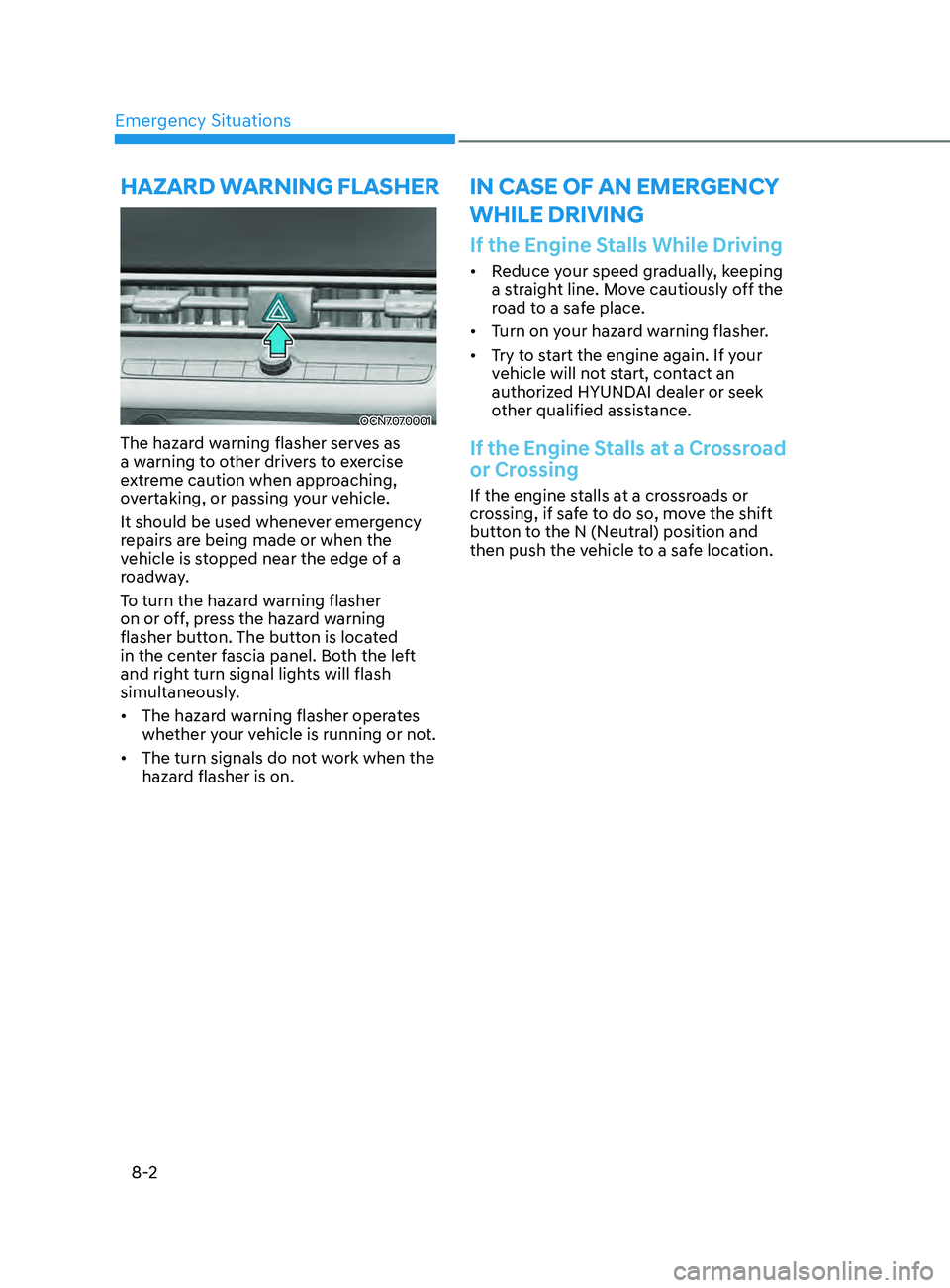
OCN7070001
The hazard warning flasher serves as
a warning to other drivers to exercise
extreme caution when approaching,
overtaking, or passing your vehicle.
It should be used whenever emergency
repairs are being made or when the
vehicle is stopped near the edge of a
roadway.
To turn the hazard warning flasher
on or off, press the hazard warning
flasher button. The button is located
in the center fascia panel. Both the left
and right turn signal lights will flash
simultaneously.
• The hazard warning flasher operates
whether your vehicle is running or not.
• The turn signals do not work when the
hazard flasher is on.
hazarD WarnIng flasher
Page 468 of 570
08
8-5
Jump starting procedure
1. Position the vehicles close enough
that the jumper cables will reach, but
do not allow the vehicles to touch.
2.
Av
oid fans or any moving parts in the
engine compartment at all times, even
when the vehicles are turned off.
3.
Turn o
ff all electrical devices such as
radios, lights, air conditioning, etc.
Put the vehicle in P (Park), and set the
parking brakes. Turn both vehicles
OFF.
OCN7070002
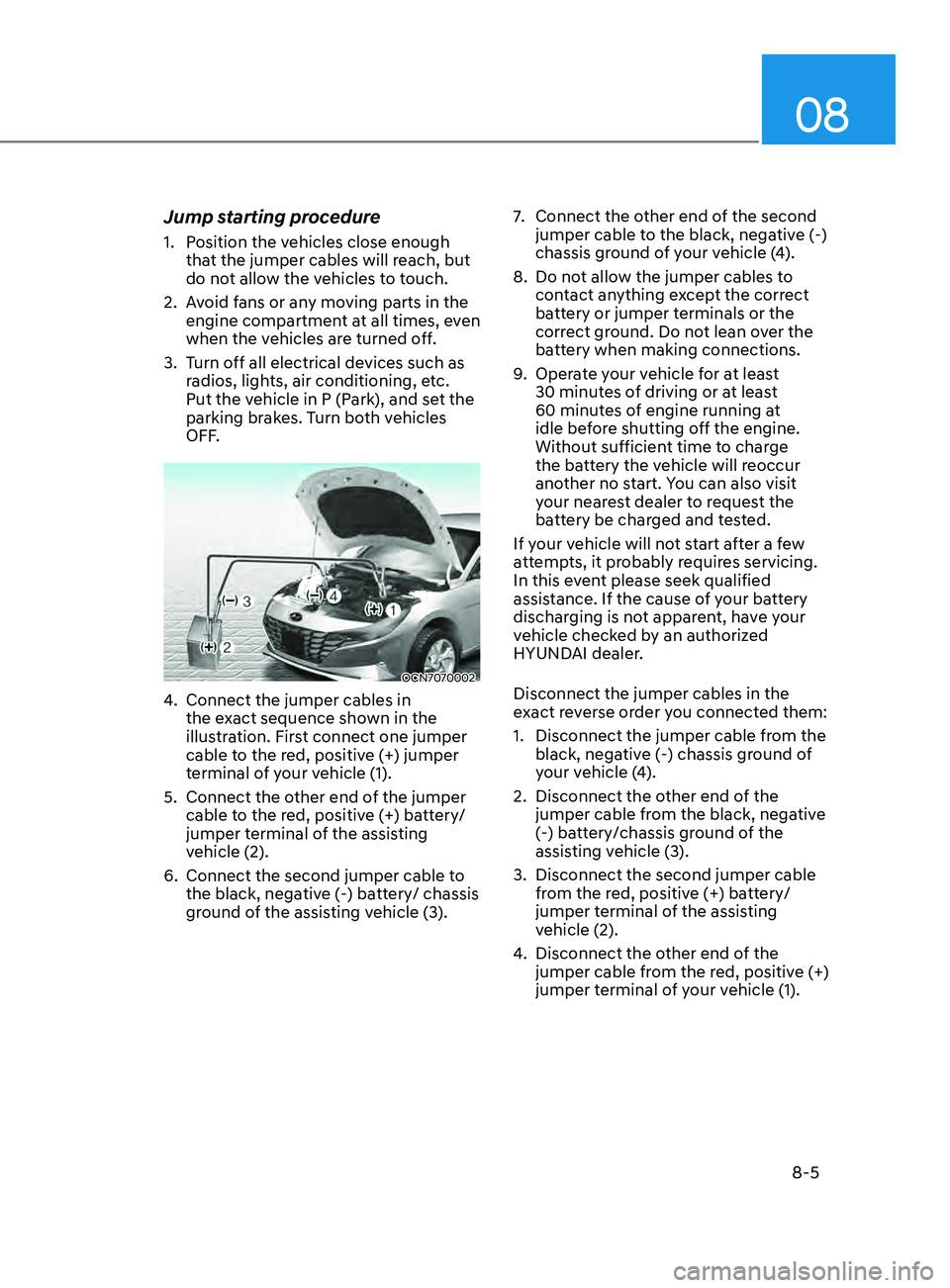
4. Connect the jumper cables in
the ex act sequence shown in the
illustration. First connect one jumper
cable to the red, positive (+) jumper
terminal of your vehicle (1).
5.
Connect the other end o
f the jumper
cable to the red, positive (+) battery/
jumper terminal of the assisting
vehicle (2).
6.
Connect the second jumper cable to
the black, nega
tive (-) battery/ chassis
ground of the assisting vehicle (3). 7.
Connect the other end o
f the second
jumper cable to the black, negative (-)
chassis ground of your vehicle (4).
8.
Do not allo
w the jumper cables to
contact anything except the correct
battery or jumper terminals or the
correct ground. Do not lean over the
battery when making connections.
9.
Opera
te your vehicle for at least
30 minutes of driving or at least
60 minutes of engine running at
idle before shutting off the engine.
Without sufficient time to charge
the battery the vehicle will reoccur
another no start. You can also visit
your nearest dealer to request the
battery be charged and tested.
If your vehicle will not start after a few
attempts, it probably requires servicing.
In this event please seek qualified
assistance. If the cause of your battery
discharging is not apparent, have your
vehicle checked by an authorized
HYUNDAI dealer.
Disconnect the jumper cables in the
exact reverse order you connected them:
1.
Disconnect the jumper cable from the
black, nega
tive (-) chassis ground of
your vehicle (4).
2.
Disconnect the other end o
f the
jumper cable from the black, negative
(-) battery/chassis ground of the
assisting vehicle (3).
3.
Disconnect the second jumper cable
from the r
ed, positive (+) battery/
jumper terminal of the assisting
vehicle (2).
4.
Disconnect the other end o
f the
jumper cable from the red, positive (+)
jumper terminal of your vehicle (1).
Page 492 of 570

Maintenance
9-6
While operating your vehicle:
• Note any changes in the sound of the
exhaust or any smell of exhaust fumes
in the vehicle.
• Check for vibrations in the steering
wheel. Notice if there is any increased
steering effort or looseness in the
steering wheel, or change in its
straight-ahead position.
• Notice if your vehicle constantly turns
slightly or “pulls” to one side when
traveling on smooth, level road.
• When stopping, listen and check for
unusual sounds, pulling to one side,
increased brake pedal travel or “hard-
to-push” brake pedal.
• If any slipping or changes in the
operation of your transmission occurs,
check the transmission fluid level.
• Check the intelligent variable
transmission P (Park) function.
• Check the parking brake.
• Check for fluid leaks under your
vehicle (water dripping from the air
conditioning system during or after
use is normal).
At least monthly:
• Check coolant level in the engine
coolant reservoir.
• Check the operation of all exterior
lights, including the brake lights, turn
signals and hazard warning flashers.
• Check the inflation pressures of all
tires including the spare for tires that
are worn, show uneven wear, or are
damaged.
• Check for loose wheel lug nuts.
At least twice a year:
(i.e., every Spring and Autumn)
• Check radiator, heater and air
conditioning hoses for leaks or
damage.
• Check windshield washer spray and
wiper operation. Clean wiper blades
with a clean cloth dampened with
washer a fluid.
• Check headlamp alignment.
• Check muffler, exhaust pipes, shields
and clamps.
• Check the seat belts for wear and
function.
At least once a year:
• Clean body and door drain holes.
• Lubricate door hinges and hood
hinges.
• Lubricate door and hood locks and
latches.
• Lubricate door rubber weather strips.
• Lubricate door checker.
• Check the air conditioning system.
• Inspect and lubricate intelligent
variable transmission linkage and
controls.
• Clean the battery and terminals.
• Check the brake fluid level.
Page 526 of 570
Maintenance9-40
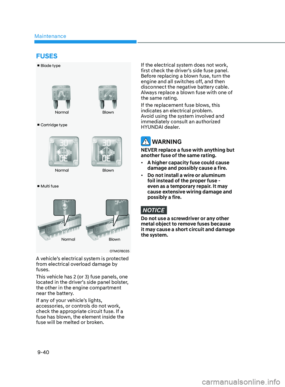
■ Cartridge type
■ Blade type
■ Multi fuse Normal
Blown
Normal Blown
Normal Blown
OTM078035
A vehicle’s electrical system is protected
from electrical overload damage by
fuses.
This vehicle has 2 (or 3) fuse panels, one
located in the driver’s side panel bolster,
the other in the engine compartment
near the battery.
If any of your vehicle’s lights,
accessories, or controls do not work,
check the appropriate circuit fuse. If a
fuse has blown, the element inside the
fuse will be melted or broken.
If the electrical system does not work,
first check the driver’s side fuse panel.
Before replacing a blown fuse, turn the
engine and all switches off, and then
disconnect the negative battery cable.
Always replace a blown fuse with one of
the same rating.
If the replacement fuse blows, this
indicates an electrical problem.
Avoid using the system involved and
immediately consult an authorized
HYUNDAI dealer.
WARNING
NEVER replace a fuse with anything but
another fuse of the same rating.
• A higher capacity fuse could cause
damage and possibly cause a fire.
• Do not install a wire or aluminum
foil instead of the proper fuse -
even as a temporary repair. It may
cause extensive wiring damage and
possibly a fire.
NOTICE
Do not use a screwdriver or any other
metal object to remove fuses because
it may cause a short circuit and damage
the system.
fuSES
Page 544 of 570

Maintenance
9-58
Interior Light Bulb Replacement
„„Sunvisor lamp
OCN7050058
„„Trunk room lamp
OCN7050059
„„Map lamp
OCN7080033
„„Room lamp
OCN7080034
1. Using a flat-blade screwdriver, gently pry the lens from the interior lamp housing.
2.
Remo
ve the bulb by pulling it straight out.
WARNING
Prior to working on the Interior Lights, ensure that the “OFF” button is depressed to
avoid burning your fingers or receiving an electric shock.
3.
Install a ne
w bulb in the socket.
4.
Align the lens tabs with the int
erior lamp housing notches and snap the lens into
place.
NOTICE
Use care not to dirty or damage lens, lens tab, and plastic housings.
Page 562 of 570
I
I-5
Exterior Lights ........................................................................\
.............................5-68
Battery saver function ........................................................................\
..............5-71
Headlamp delay function ........................................................................\
.........5-71
High beam operation ........................................................................\
................ 5-69
Lighting control ........................................................................\
........................ 5-68
Turn signals and lane change signals ...............................................................5-70
Exterior Overview
........................................................................\
......................... 2-2
F
Filter Inspection
........................................................................\
........................... 9-21
Filter replacement ........................................................................\
.....................9-21
Forward Collision–A
voidance Assist (FCA) (front view camera only)
...............7-2
Function malfunction and limitations ................................................................ 7-7
Function operation ........................................................................\
...................... 7-5
Function settings ........................................................................\
........................ 7-3
Forward Collision–A
voidance Assist (FCA) (sensor fusion)
..............................7-14
Function malfunction and limitations .............................................................. 7-22
Function operation ........................................................................\
.................... 7-18
Function settings ........................................................................\
...................... 7-16
Fuel Filler Door
........................................................................\
........................... 5-66
Fuel Requirements
........................................................................\
......................... 1-5
Fuses
........................................................................\
............................................ 9-40
Engine Compartment Panel Fuse Replacement ...............................................9-42
Fuse/Relay Panel Description ........................................................................\
.. 9-43
Instrument Panel Fuse Replacement ................................................................9-41
G
Guide to Hyundai Genuine Parts
........................................................................\
... 1-3
H
Hazard W
arning Flasher
........................................................................\
................ 8-2
High Beam
Assist (HBA)
........................................................................\
........... 5-72
Detecting sensor (Front view camera) .............................................................5-72
Function malfunction and limitations .............................................................. 5-73
Function operation ........................................................................\
.................... 5-73
Function settings ........................................................................\
...................... 5-72
Page 564 of 570
I
I -7
Instrument Cluster ........................................................................\
.........................4-4
Gauges and Meters ........................................................................\
.....................4-5
Instrument Cluster Control ........................................................................\
.........4-5
LCD Display Messages ........................................................................\
............ 4-19
Transmission shift indicator ........................................................................\
.......4-9
Warning and Indicator Lights ........................................................................\
.....4-9
Instrument Panel Overview
........................................................................\
........... 2-5
Intelligent Speed Limit
Assist (ISLA)
................................................................ 7-66
Function malfunction and limitations ..............................................................7-69
Function operation ........................................................................\
.................... 7-67
Function settings ........................................................................\
...................... 7-66
Intelligent
Variable Transmission
........................................................................\
6-12
Good driving practices ........................................................................\
............. 6-18
Intelligent variable transmission operation ......................................................6-12
Parking ........................................................................\
..................................... 6-17
Interior Features
........................................................................\
......................... 5
-111
Clock ........................................................................\
......................................5-1
16
Clothes Hanger ........................................................................\
.......................5-1
16
Cup Holder ........................................................................\
.............................5
-111
Power Outlet ........................................................................\
...........................5-1
12
Sunvisor ........................................................................\
..................................5-1
12
USB Charger ........................................................................\
..........................5-1
13
Wireless Cellular Phone Char
ging System
..................................................... 5-1
14
Interior Lights
........................................................................\
.............................. 5-75
Front lamps ........................................................................\
............................... 5-75
Interior lamp AUT
O cut
........................................................................\
........... 5-75
Luggage compartment lamp ........................................................................\
.....5-77
Rear lamp ........................................................................\
................................. 5-76
Vanity mirror lamp ........................................................................\
...................5-77
Welcome system ........................................................................\
....................... 5-78
Interior Overview
........................................................................\
........................... 2-4
ISG (Idle Stop and Go) system
........................................................................\
.... 6-35
Battery Sensor Deactivation ........................................................................\
..... 6-38
ISG System Malfunction ........................................................................\
.......... 6-37
To
Activate the ISG System
........................................................................\
..... 6-35
To Deactivate the ISG System ........................................................................\
6-37