HYUNDAI ENTOURAGE 2007 Owners Manual
Manufacturer: HYUNDAI, Model Year: 2007, Model line: ENTOURAGE, Model: HYUNDAI ENTOURAGE 2007Pages: 398, PDF Size: 8.03 MB
Page 341 of 398
627
Maintenance
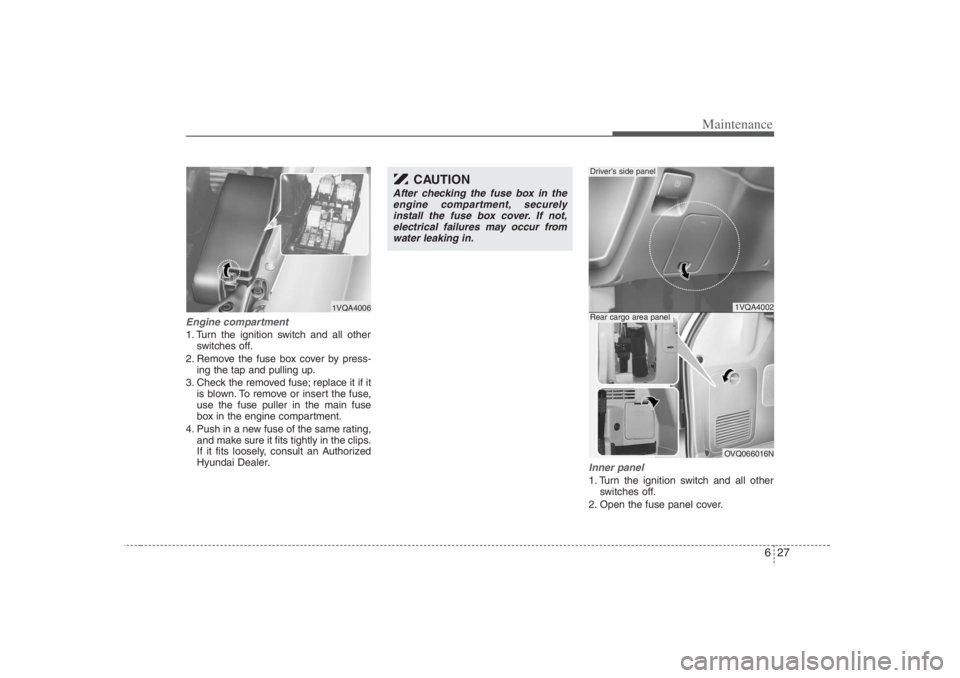
Engine compartment1. Turn the ignition switch and all other
switches off.
2. Remove the fuse box cover by press-
ing the tap and pulling up.
3. Check the removed fuse; replace it if it
is blown. To remove or insert the fuse,
use the fuse puller in the main fuse
box in the engine compartment.
4. Push in a new fuse of the same rating,
and make sure it fits tightly in the clips.
If it fits loosely, consult an Authorized
Hyundai Dealer.
Inner panel1. Turn the ignition switch and all other
switches off.
2. Open the fuse panel cover.
1VQA4006
CAUTION
After checking the fuse box in the
engine compartment, securely
install the fuse box cover. If not,
electrical failures may occur from
water leaking in.
1VQA4002OVQ066016N
Driver’s side panelRear cargo area panel
Page 342 of 398
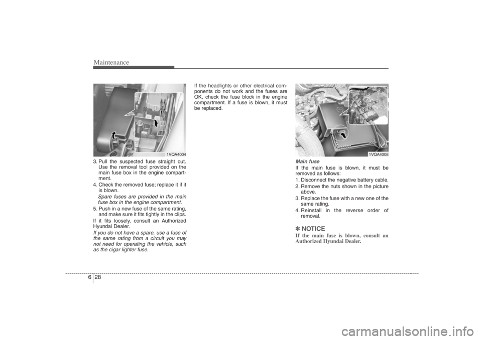
Maintenance28 63. Pull the suspected fuse straight out.
Use the removal tool provided on the
main fuse box in the engine compart-
ment.
4. Check the removed fuse; replace it if it
is blown.Spare fuses are provided in the main
fuse box in the engine compartment.5. Push in a new fuse of the same rating,
and make sure it fits tightly in the clips.
If it fits loosely, consult an Authorized
Hyundai Dealer.If you do not have a spare, use a fuse of
the same rating from a circuit you may
not need for operating the vehicle, such
as the cigar lighter fuse.
If the headlights or other electrical com-
ponents do not work and the fuses are
OK, check the fuse block in the engine
compartment. If a fuse is blown, it must
be replaced.
Main fuseIf the main fuse is blown, it must be
removed as follows:
1. Disconnect the negative battery cable.
2. Remove the nuts shown in the picture
above.
3. Replace the fuse with a new one of the
same rating.
4. Reinstall in the reverse order of
removal.✽ ✽
NOTICEIf the main fuse is blown, consult an
Authorized Hyundai Dealer.
1VQA4008
1VQA4004
Page 343 of 398
629
Maintenance
✽ ✽
NOTICENot all fuse panel descriptions in this
manual may be applicable to your vehi-
cle. It is accurate at the time of printing.
When you inspect the fuse box on your
vehicle, refer to the fuse box label.
Driver’s side panel
Engine compartment
1VQA4009/OVQ066017N/1VQA4013/OVQ046010N
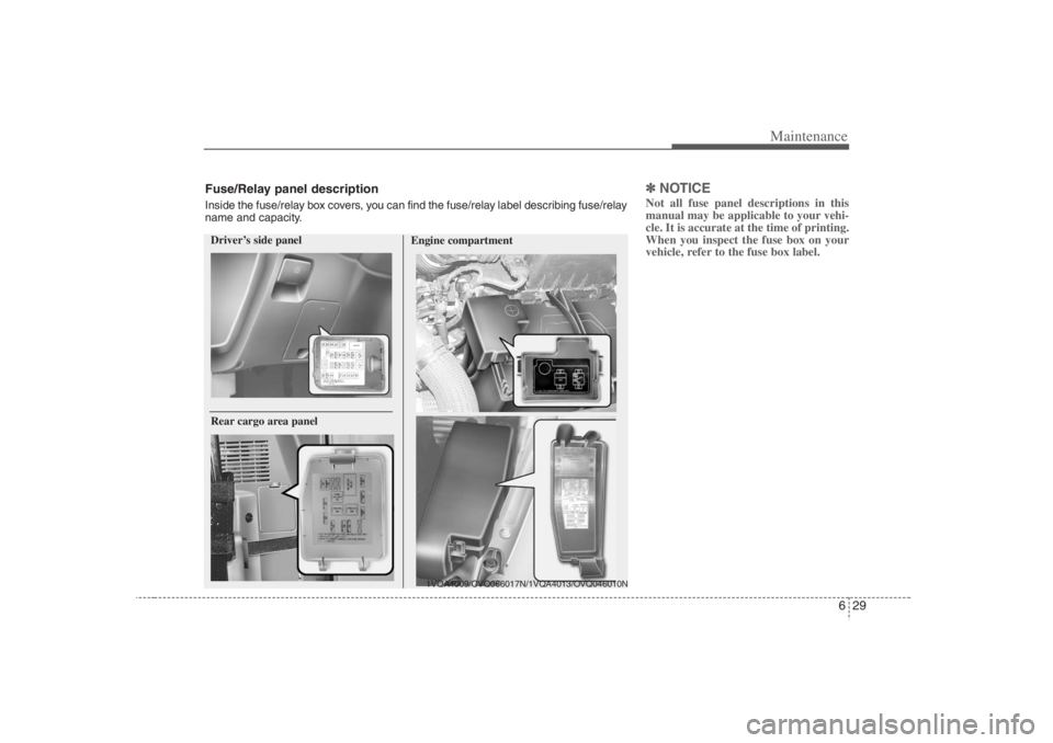
Rear cargo area panelFuse/Relay panel descriptionInside the fuse/relay box covers, you can find the fuse/relay label describing fuse/relay
name and capacity.
Page 344 of 398
Maintenance30 6Driver's side fuse panel
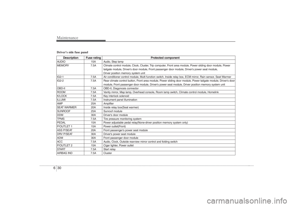
Description Fuse rating Protected component
AUDIO 15A Audio, Step lamp
MEMORY 7.5A Climate control module, Clock, Cluster, Trip computer, Front area module, Power sliding door module, Power
tailgate module, Driver's door module, Front passenger door module, Driver's power seat module,
Driver position memory system unit
IG2-1 7.5A Air conditioner control module, Multi function switch, Inside relay box, ECM mirror, Rain sensor, Seat Warmer
IG2-2 7.5A Rear climate control button, Front area module, Power sliding door module, Power tailgate module, Driver's door
module, Front passenger door module, Driver's power seat module, Driver position memory system unit
OBD-II 7.5A OBD-II, Diagonosis connector
ROOM 7.5A Vanity mirror, Map lamp, Overhead console, Room lamp switch, Climate control module, Homelink
K/LOCK 7.5A Key interlock solenoid
ILLUMI 7.5A Instrument panel illumination
AMP 25A Amplifier
SEAT WARMER 20A Inside relay box(Seat warmer)
SUNROOF 25A Sunroof module
DDM 30A Driver's door module
TPMS 7.5A Tire pressure monitoring system
PEDAL 15A Power adjustable pedal relay(None-driver position memory system only)
P/OUTLET 1 15A Power outlet(Front)
ASS P/SEAT 20A Front passenger's power seat module
DRV P/SEAT 30A Driver's power seat module
ADM 30A Front passenger door module
ACC 7.5A Audio, Clock, Outside rearview mirror control and folding switch
P/OUTLET 2 15A Cigar lighter, Power outlet
START 7.5A Start relay
AIRBAG IND 7.5A Cluster
Page 345 of 398
631
Maintenance
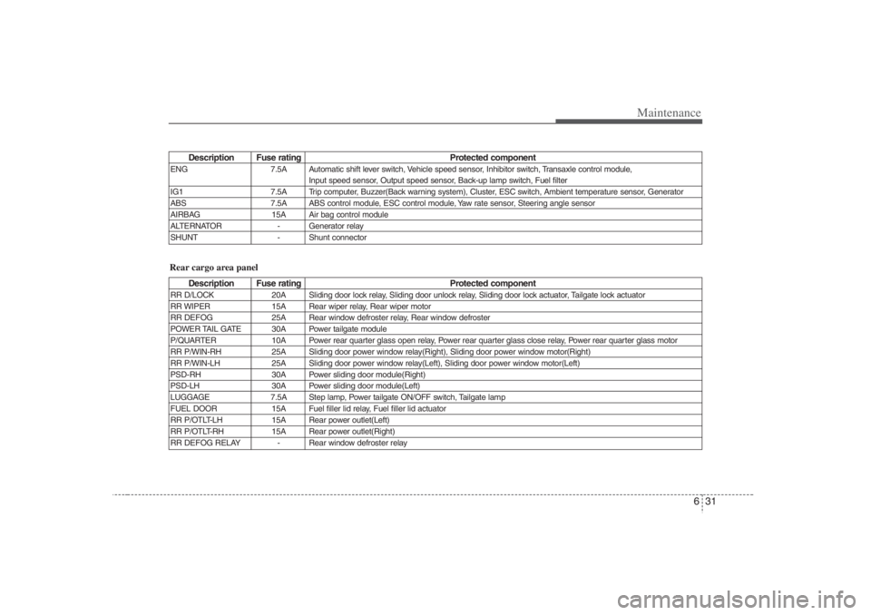
Description Fuse rating Protected component
ENG 7.5A Automatic shift lever switch, Vehicle speed sensor, Inhibitor switch, Transaxle control module,
Input speed sensor, Output speed sensor, Back-up lamp switch, Fuel filter
IG1 7.5A Trip computer, Buzzer(Back warning system), Cluster, ESC switch, Ambient temperature sensor, Generator
ABS 7.5A ABS control module, ESC control module, Yaw rate sensor, Steering angle sensor
AIRBAG 15A Air bag control module
ALTERNATOR - Generator relay
SHUNT - Shunt connector
Description Fuse rating Protected component
RR D/LOCK 20A Sliding door lock relay, Sliding door unlock relay, Sliding door lock actuator, Tailgate lock actuator
RR WIPER 15A Rear wiper relay, Rear wiper motor
RR DEFOG 25A Rear window defroster relay, Rear window defroster
POWER TAIL GATE 30A Power tailgate module
P/QUARTER 10A Power rear quarter glass open relay, Power rear quarter glass close relay, Power rear quarter glass motor
RR P/WIN-RH 25A Sliding door power window relay(Right), Sliding door power window motor(Right)
RR P/WIN-LH 25A Sliding door power window relay(Left), Sliding door power window motor(Left)
PSD-RH 30A Power sliding door module(Right)
PSD-LH 30A Power sliding door module(Left)
LUGGAGE 7.5A Step lamp, Power tailgate ON/OFF switch, Tailgate lamp
FUEL DOOR 15A Fuel filler lid relay, Fuel filler lid actuator
RR P/OTLT-LH 15A Rear power outlet(Left)
RR P/OTLT-RH 15A Rear power outlet(Right)
RR DEFOG RELAY - Rear window defroster relayRear cargo area panel
Page 346 of 398
Maintenance32 6
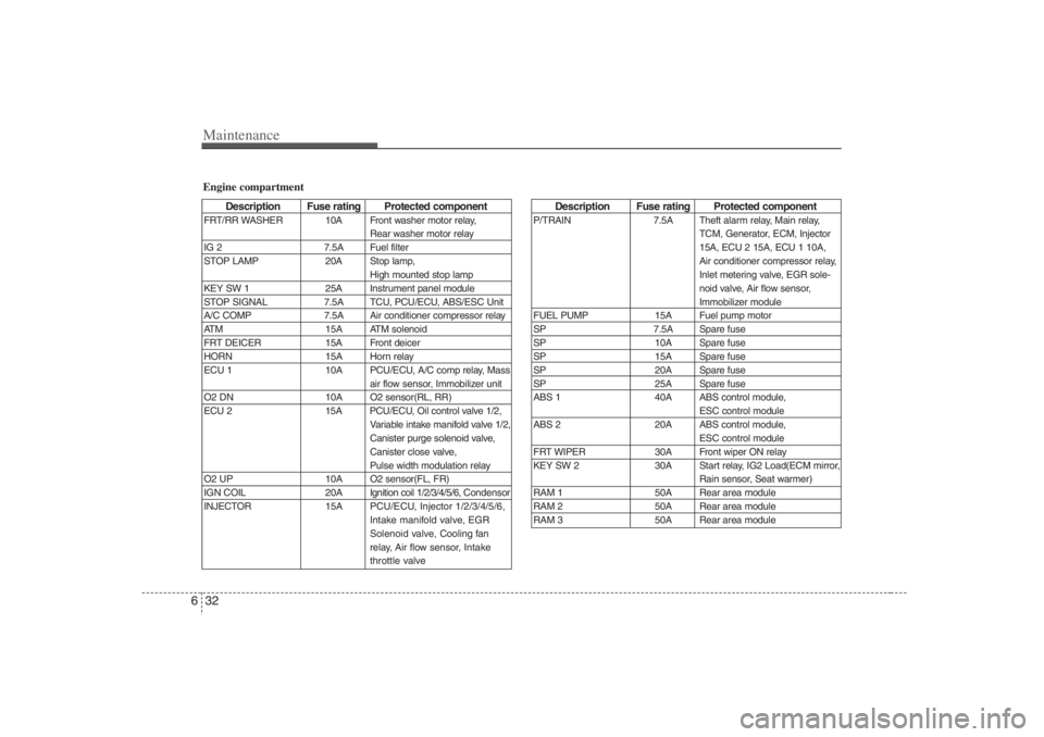
Description Fuse rating Protected component
P/TRAIN 7.5A Theft alarm relay, Main relay,
TCM, Generator, ECM, Injector
15A, ECU 2 15A, ECU 1 10A,
Air conditioner compressor relay,
Inlet metering valve, EGR sole-
noid valve, Air flow sensor,
Immobilizer module
FUEL PUMP 15A Fuel pump motor
SP 7.5A Spare fuse
SP 10A Spare fuse
SP 15A Spare fuse
SP 20A Spare fuse
SP 25A Spare fuse
ABS 1 40A ABS control module,
ESC control module
ABS 2 20A ABS control module,
ESC control module
FRT WIPER 30A Front wiper ON relay
KEY SW 2 30A Start relay, IG2 Load(ECM mirror,
Rain sensor, Seat warmer)
RAM 1 50A Rear area module
RAM 2 50A Rear area module
RAM 3 50A Rear area module
Engine compartment
Description Fuse rating Protected component
FRT/RR WASHER 10A Front washer motor relay,
Rear washer motor relay
IG 2 7.5A Fuel filter
STOP LAMP 20A Stop lamp,
High mounted stop lamp
KEY SW 1 25A Instrument panel module
STOP SIGNAL 7.5A TCU, PCU/ECU, ABS/ESC Unit
A/C COMP 7.5A Air conditioner compressor relay
ATM 15A ATM solenoid
FRT DEICER 15A Front deicer
HORN 15A Horn relay
ECU 1 10A PCU/ECU, A/C comp relay, Mass
air flow sensor, Immobilizer unit
O2 DN 10A O2 sensor(RL, RR)
ECU 2 15A PCU/ECU, Oil control valve 1/2,
Variable intake manifold valve 1/2,
Canister purge solenoid valve,
Canister close valve,
Pulse width modulation relay
O2 UP 10A O2 sensor(FL, FR)
IGN COIL 20AIgnition coil 1/2/3/4/5/6, Condensor
INJECTOR 15APCU/ECU, Injector 1/2/3/4/5/6,
Intake manifold valve, EGR
Solenoid valve, Cooling fan
relay, Air flow sensor,Intake
throttle valve
Page 347 of 398
633
Maintenance
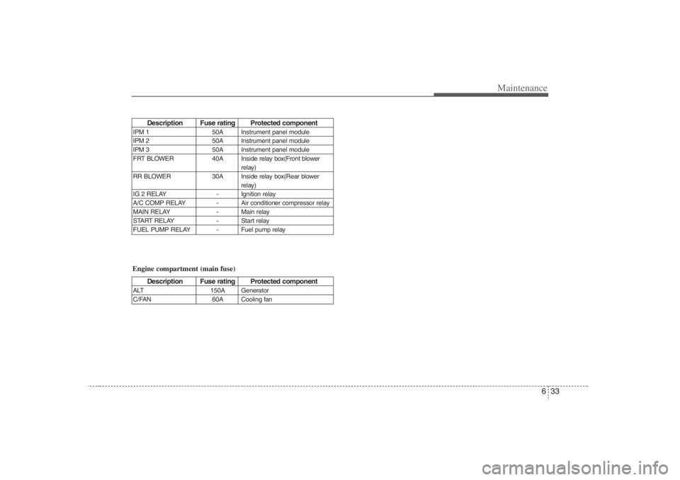
Description Fuse rating Protected component
IPM 1 50A Instrument panel module
IPM 2 50A Instrument panel module
IPM 3 50A Instrument panel module
FRT BLOWER 40A Inside relay box(Front blower
relay)
RR BLOWER 30A Inside relay box(Rear blower
relay)
IG 2 RELAY - Ignition relay
A/C COMP RELAY - Air conditioner compressor relay
MAIN RELAY - Main relay
START RELAY - Start relay
FUEL PUMP RELAY - Fuel pump relayEngine compartment (main fuse)
Description Fuse rating Protected component
ALT 150A Generator
C/FAN 60A Cooling fan
Page 348 of 398
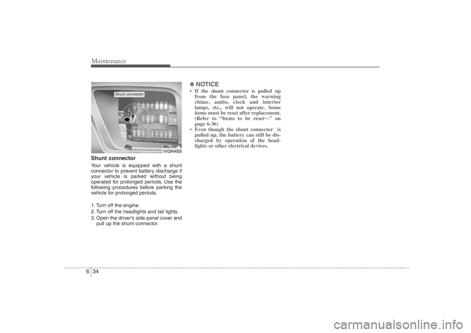
Maintenance34 6Shunt connector Your vehicle is equipped with a shunt
connector to prevent battery discharge if
your vehicle is parked without being
operated for prolonged periods. Use the
following procedures before parking the
vehicle for prolonged periods.
1. Turn off the engine.
2. Turn off the headlights and tail lights.
3. Open the driver’s side panel cover and
pull up the shunt connector.
✽ ✽
NOTICE• If the shunt connector is pulled up
from the fuse panel, the warning
chime, audio, clock and interior
lamps, etc., will not operate. Some
items must be reset after replacement.
(Refer to “Items to be reset···.” on
page 6-36)
• Even though the shunt connector is
pulled up, the battery can still be dis-
charged by operation of the head-
lights or other electrical devices.
1VQA4005
Shunt connector
Page 349 of 398
635
Maintenance
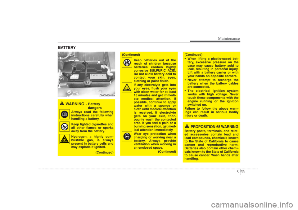
BATTERY
WARNING
- Battery
dangers
Always read the following
instructions carefully when
handling a battery.
Keep lighted cigarettes and
all other flames or sparks
away from the battery.
Hydrogen, a highly com-
bustible gas, is always
present in battery cells and
may explode if ignited.
(Continued)
(Continued)
Keep batteries out of the
reach of children because
batteries contain highly
corrosive SULFURIC ACID.
Do not allow battery acid to
contact your skin, eyes,
clothing or paint finish.
If any electrolyte gets into
your eyes, flush your eyes
with clean water for at least
15 minutes and get immedi-
ate medical attention. If
possible, continue to apply
water with a sponge or
cloth until medical attention
is received. If electrolyte
gets on your skin, thor-
oughly wash the contacted
area. If you feel a pain or a
burning sensation, get med-
ical attention immediately.
Wear eye protection when
charging or working near a
battery. Always provide
ventilation when working in
an enclosed space.
(Continued)
(Continued)
When lifting a plastic-cased bat-
tery, excessive pressure on the
case may cause battery acid to
leak, resulting in personal injury.
Lift with a battery carrier or with
your hands on opposite corners.
Never attempt to recharge the
battery when the battery cables
are connected.
The electrical ignition system
works with high voltage. Never
touch these components with the
engine running or the ignition
switched on.
Failure to follow the above warn-
ings can result in serious bodily
injury or death.
PROPOSITION 65 WARNING
Battery posts, terminals, and relat-
ed accessories contain lead and
lead compounds, chemicals known
to the State of California to cause
cancer and reproductive harm.
Batteries also contain other chemi-
cals known to the State of California
to cause cancer. Wash hands after
handling.
OVQ066018N
Page 350 of 398
Maintenance36 6For best battery service: Keep the battery securely mounted.
Keep the battery top clean and dry.
Keep the terminals and connections
clean, tight, and coated with petroleum
jelly or terminal grease.
Rinse any spilled electrolyte from the
battery immediately with a solution of
water and baking soda.
If the vehicle is not going to be used for
an extended time, disconnect the bat-
tery cables.Battery recharging Your vehicle has a maintenance-free,
calcium-based battery.
If the battery becomes discharged in a
short time (because, for example, the
headlights or interior lights were left on
while the vehicle was not in use),
recharge it by slow charging (trickle)
for 10 hours.
If the battery gradually discharges
because of high electric load while the
vehicle is being used, recharge it at 20-
30A for two hours.
Items to be reset after the battery
has been discharged or the bat-
tery has been disconnected. Clock (See Chapter 3)
Sunroof (See Chapter 3)
Trip computer (See Chapter 3)
Climate control system (See Chapter
3)
Audio (See Chapter 3)
Power sliding door and power tailgate
(See Chapter 3)
CAUTION
Before performing maintenance
or recharging the battery, turn off
all accessories and stop the
engine.
The negative battery cable must
be removed first and installed last
when the battery is disconnected.
WARNING
- Recharging
battery
When recharging the battery,
observe the following precautions:
The battery must be removed
from the vehicle and placed in an
area with good ventilation.
Do not allow cigarettes, sparks, or
flame near the battery.
Watch the battery during charg-
ing, and stop or reduce the charg-
ing rate if the battery cells begin
gassing (boiling) violently or if
the temperature of the electrolyte
of any cell exceeds 120°F (49°C).
(Continued)
(Continued)
Wear eye protection when check-
ing the battery during charging.
Disconnect the battery charger in
the following order.
1. Turn off the battery charger main
switch.
2. Unhook the negative clamp from
the negative battery terminal.
3. Unhook the positive clamp from
the positive battery terminal.